1
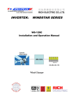
C12 Charge/Load/Lighting Controller
Owner’s Manual
t
f
e
1-800-670-0707 (toll free in North America)
1-360-925-5097 (direct)
1-800-994-7828 (toll free in North America)
1-360-925-5143 (direct)
[email protected]
www.xantrex.com
March 2005
975-0130-01-01 Rev. D
Printed in China
Xantrex C12 Charge/ Load / Lighting Controller Owner’s Manual
Introducing the C12
The Xantrex Technology C12 charge/load controller is the finest small
system charge/load controller available and has many capabilities
previously either non-existent, or found only in separate products.
Numerous standard features maximize the performance of the system:
• Designed to meet the National Electric Code and other international
controller specifications..
• Electronic overload and short circuit protection with automatic and
manual reset ability. Increases the reliability of unattended systems
by eliminating blown fuses or tripped circuit breakers.
• Field adjustment of the setpoints is provided by rotary controls with
removable knobs to reduce the potential for setpoint tampering.
Includes calibrated scales for adjustment of the settings and
testpoints to verify setpoints using a digital meter (not required).
• Optional external plug-in temperature compensation sensor for
automatic adjustment of the charge controller setpoints to the battery
temperature. This UL requirement is also strongly recommended for
sealed batteries.
• Over-temperature protection of the electronic circuitry is provided by
reducing the charge rate. This improves the reliability of the C12
when used in very hot environments (over 113°F / 45°C ambient).
• Multi-color LED with matching color label for mode/status indication.
• Suitable for outdoor use when protected from direct rain and sunlight.
• 2 year limited warranty
These instructions only apply to the C12 REV D or later.
Operating Modes
The model C12 charge/load controller can operate in one or more of
the following modes:
•
Photovoltaic Charge Control Mode with 3-stage
regulation and automatic or manual battery equalization cycle.
•
DC Load Control Mode includes automatic low battery
disconnect with warning by flashing the loads. In manual mode the
reset switch allows one 10-minute “grace period” of load operation.
•
NITE-LITE Mode with automatic dusk detection and adjustable
time period from 10 minutes to 9.5 hours duration or dusk to dawn
operation with a 20 hour limit.
Photovoltaic Charge Control Mode
3-Stage Regulation
The C12 charge controller rapidly cycles the photovoltaic array on and
off to control the charging of the battery. The battery voltage will vary
during the charging process, as follows:
1.
BULK—During this stage the PV array is allowed to charge at its
full output. Once the voltage of the battery reaches the BULK
voltage setting, the controller goes to the next stage.
2.
ABSORPTION—During this stage the voltage of the battery is
held at the BULK voltage setting until a timer accumulates 1 hour.
3.
FLOAT—During this stage the voltage of the battery is held at
the FLOAT voltage setting. Full current from the PV array can still
be delivered to the loads during this stage.
If the voltage of the battery drops below the FLOAT setting for a
cumulative period of one hour, a new BULK or ABSORPTION cycle will
be triggered. This typically occurs during each night. If the battery is full
at the start of the day, it will receive only an ABSORPTION charge for 1
hour and then be held at the FLOAT setting for the remaining period of
the day unless the battery is discharged.
array’s limited output. The final FLOAT voltage setting reduces gassing
of the battery, minimizing watering requirements and ensuring the
complete recharge of the battery.
Automatic PV Array Night Disconnection
Each night the PV array is automatically disconnected from the battery
to prevent reverse leakage of power. This eliminates the need for a
blocking diode between the battery and the PV array. If you are using
thin-film or amorphous solar modules, diodes may still be required to
prevent damage from partial shading conditions. Check the
documentation provided for the requirements of your PV modules.
Equalization (Non-Sealed Batteries Only)
Approximately every month, the batteries may need to be "equalized"
(a fancy term for over-charged). Since the individual cells of the battery
are not identical, some cells may not be fully charged when the
charging process is completed. Or, if the batteries have been left
uncharged for periods of time, the plates will have sulfates on them. If
the sulfate remains on the plates for an extended period of time, it will
harden and seal off a percentage of the plate area, reducing the
capacity of the battery. By equalizing the batteries, the sulfate is
removed from the plates.
Additionally, batteries with liquid electrolyte may become stratified.
Stratification concentrates the sulfuric acid into the bottom of the cell
while the top becomes diluted. This corrodes the lower portion of the
plates, reducing battery life. Mixing of the electrolyte by the formation
of gas bubbles during the equalization process reduces stratification.
You can check if a battery needs to be equalized by two methods. If
you can measure the voltage of each individual cell, a variation of 0.05
volts between cells indicates an imbalance exists. If the battery
construction prevents measurement of the individual cell voltages, use
a hydrometer. If you can measure the specific gravity of each of the
battery cells, a variation of 0.020 is considered significant. Both
conditions may be corrected by an equalization charge.
A proper equalization charge will not damage a vented, liquid
electrolyte type battery. It may, however, cause significant electrolyte
usage and require that the battery be refilled with distilled water to the
correct level. This may be a problem with unattended systems in
remote areas that do not receive regular maintenance. Consult the
battery manufacturer for their recommendations.
CAUTION: Equalization should only be done with vented (not
sealed or maintenance free) lead acid, liquid electrolyte batteries.
The battery manufacturer should be consulted before attempting
to equalize any other type battery. Clean, distilled water will need
to be added to the battery AFTER the equalization process.
DC loads may need to be disconnected by turning off circuit
breakers or removing fuses before equalization to prevent
damage by the required higher voltages. Just turning off the DC
loads by its on/off switch may not provide protection.
WARNING: If the batteries are equipped with HYDROCAPS
(catalytic gas recombiner caps), they should be removed during
the equalization process. If hydrocaps are used, you should
disable automatic equalization to prevent possible damage.
The C12 includes both automatic and manual triggering of the
equalization process. Automatic equalization is enabled by removing
the jumper located on bottom right corner the circuit board next to the
reset switch (the default setting is disabled). An equalization charge,
(holding the voltage 1 volt above bulk for 2 hours) will occur every 30
days or once the system has reached the LVD level for a period of two
minutes or longer. The default setting is auto equalization disabled.
Manual equalization is not available when the C12 is used in the NITELITE mode because the reset switch provides a test function of the
loads instead (this only applies to the NITE-LITE mode).
This 3-stage charging process results in faster recharging of batteries
compared to on-off or constant voltage regulators. Faster recharging
increases the performance of the system by storing more of the PV
2
975-0130-01-01
Xantrex C12 Charge/ Load / Lighting Controller Owner’s Manual
Manual Equalization
Over-temperature Protection
Manual equalization of the battery can be enabled by pressing and
holding the reset switch until the LED indicator begins to alternate
between red and green. The equalization process will continue until the
batteries have been held above the bulk setting for two hours of
accumulated time. The battery voltage will be limited to 1 volt above
the BULK setting during this period. Once two hours have been
accumulated, the C12 will return to the FLOAT stage of the charging
process (with NiCad batteries the battery voltage is held at the BULK
setting for a two hour period before it returns to the float level).
The temperature of the C12’s transistors is also continuously
monitored. This protects the charge controller from damage in hightemperature environments. If excessive temperatures are detected, the
charge control transistor is rapidly turned off and on to reduce the
charge rate. This will reduce the transistor temperature.
To stop the equalization process, press and hold the reset switch until
the LED stops alternating between red and green. If the equalization
process was shorter than 1 hour, the C12 will continue with a BULK
charge cycle and then hold the battery at the BULK setting for one hour
(the absorption stage) before returning to the FLOAT setting.
The C12 is rated for 12 amps continuous at up to 45°C/113°F and 8
amps at up to 65°C/150°F.
During the equalization process the LED will alternate between red and
green and will not provide any other mode/status indication.
Manual equalization is not available when operating the controller in
the NITE-LITE mode. Pressing the reset switch in this mode provides a
test of the loads (the lights) for a period of two minutes.
Automatic Equalization
The C12 can automatically trigger an equalization charge every 30
days or after the voltage drops below the LVD setting for a period of
two minutes. The LED will indicate that the equalization process is
occurring only once the battery voltage has risen above the bulk
setting.
To enable automatic equalization, the jumper located at the bottom
right corner of the circuit board must be removed. The default setting of
the C12 is automatic equalization disabled.
To stop the equalization process, press and hold the reset switch on
the bottom of the C12 until the LED indicator stops alternating between
red and green. If the equalization process was shorter than 1 hour, the
C12 will continue with a BULK charge cycle and then hold the battery
at the BULK setting for one hour (the absorption stage) before
returning to the FLOAT setting.
Electronic Overcurrent Protection
During operation, the C12 continuously monitors the current flowing
into and out of the battery. If the current exceeds 15 amps the
transistor switches are opened, stopping the flow of electricity. This
protects the loads and array wiring from short circuits and overloads.
The detection circuitry is faster than breakers or fuses—they will not
trip or blow when a fault occurs because the C12 will protect sooner.
The C12 will automatically attempt to restart the load 12 seconds after
the overcurrent condition was detected. If the overcurrent reoccurs
when the system is re-energized, it turns off again. A second attempt to
restart the system will occur after an additional 12 seconds. If this fails,
the C12 will try to restart the system every 15 minutes.
The reset switch on the bottom of the C12 allows the user to attempt a
manual restart at any time. When the controller is unable to
automatically restart the system, check the wiring and reduce the loads
connected. Allow for up to a 12-second delay after pressing the reset
switch for the restart to occur.
The current shunt which is used to measure the current flow is located
in the positive conductor of the circuit. This allows you to use any
combination of the negative terminals, as they are all common to one
another.
Temperature Compensation
The optional plug-in external temperature sensor automatically finetunes the charging process of the C12. If the temperature sensor is
installed, the regulation setpoints should be adjusted for a battery at
23°C/74°F. The C12 adjusts the BULK and FLOAT setpoints -0.03v per
°C for lead acid type batteries and -0.02v per °C for NiCad type
batteries.
If the temperature sensor is not installed, the setpoints should be
adjusted to account for the temperature of the battery during operation.
Seasonal adjustment of the setpoints may be necessary to prevent
battery damage and to ensure proper charging.
975-0130-01-01
If the PV array current is reduced to zero and the over-temperature
condition continues, the load will be disconnected. Once the
temperature has dropped, the PV array and then the loads will be
reconnected.
Battery Loss Detection
If the battery is disconnected from the system while the PV array is
charging, the C12 will prevent damage to DC loads by a high voltage
condition (over 18 volts) by disconnecting the PV array. The C12 also
prevents oscillation of the system (on-off-on...) which is common with
other controllers when the battery has been disconnected but the PV
array remains connected.
DC Load Control Mode
The C12 includes a 12-amp load control to manage the discharging of
the battery. This prevents damage to the battery from over-discharge
during periods of poor weather or excessive loads.
The C12 load controller is unique in that it includes a warning flash of
the loads (off then on) to alert the user that the load will be turned off
after an additional 5 minute delay period. This gives the user an
opportunity to reduce the loads and extend operation of the system.
Once the load has been disconnected, the user is given a one time;
10-minute “grace” period of load operation immediately after the reset
switch has been pressed. This allows the user to operate critical loads
for a limited period. The small additional discharge of the battery will
not cause any harm.
Reconnection of the load is allowed once the battery voltage has
exceeded the Low Voltage Reconnect (LVR) setting. The default
setting of the C12 is manual reconnection (MANUAL) of the loads after
the system has reached the LVD state. Manual reconnect is selected
by turning the bottom knob fully counter-clockwise to MANUAL.
Automatic Reconnection
Automatic reconnection of the loads at the LVR setting can be enabled
by adjusting the bottom-most knob to the area marked as AUTO
RECON instead of the default MANUAL area.
In automatic reconnection mode, no warning flash of the loads is
provided. Pressing the reset switch does not provide the one time, 10
minute additional “grace period” of load operation included in the
manual reconnection mode.
The low voltage disconnect includes a 2 minute delay before
disconnecting the loads when the voltage drops below the LVD setting
when automatic reconnection is selected.
NITE-LITE Mode
The C12 can also be used to automatically control photovoltaic lighting
systems. Up to 12 amps of lights can be controlled by the C12.
The installation and reliability of the system is maximized by using the
PV array as the photocell to provide dusk and dawn detection. When
the PV array voltage drops below 3.5 volts for a period exceeding 60
seconds, the C12 turns on the lights. If the PV array voltage exceeds
3.5 volts for 60 seconds, the C12 turns off the lights. When the PV
array voltage exceeds 9 volts the C12 resets the NITE-LITE-TIME
period counter for the next day’s operation.
To activate the NITE-LITE mode, select a run duration setting by
adjusting the knob at the bottom of the circuit board labeled as NITELITE-TIME. The minimum run time is 10 minutes and the maximum is
9.5 hours (automatic reset is standard for the NITE-LITE mode).
If the voltage falls below the LVD setting for more than 2 minutes, the
lights will be turned off to prevent damage to the battery. The LVD will
auto-reset once the charging process increases the voltage above the
3
Xantrex C12 Charge/ Load / Lighting Controller Owner’s Manual
LVR setting, usually during the next day. No warning flash occurs
before the lights are turned off when NITE-LITE mode is selected.
Dusk-Dawn Operation
is a good indication of proper system operation and will maximize
battery life and performance.
•
Blinking Green—The battery voltage is above 12.6 volts. As
the battery voltage approaches the BULK setting, the LED will blink
green several times (up to 5) and then pause. This indicates that the
battery voltage is approaching the BULK voltage setting and provides
an indication that the battery is almost full.
•
Blinking Red—The battery voltage is below 12.6 volts. As the
battery voltage approaches the Low Voltage Disconnect (LVD)
setting, the LED will blink red several times (up to 5) and then pause.
This provides an indication that the battery is almost empty.
•
Solid Red—The battery has reached the Low Voltage Disconnect
(LVD) setting. If manual reconnect mode was selected, the loads will
be turned off momentarily (flashed) to warn the user that the battery
is empty after a 2-minute delay. The loads will then be disconnected
after an additional 5-minute delay unless the user reduces the loads
to a point that the battery voltage exceeds the LVD setting. If auto
reconnect mode was selected, the loads will be turned off after a 2minute delay without any warning flash.
•
Slow Blinking Orange—The C12 has disconnected the loads
If the NITE-LITE-TIME knob is turned fully clockwise to the area
marked D-D, dawn to dusk operation will be selected. This allows the
lights to operate all night, turning on at dusk and off at dawn.
If the voltage falls below the LVD setting for more than 2 minutes, the
lights will be turned off to prevent damage to the battery. The LVD will
be reset once the charging process increases the voltage above the
LVR setting, usually during the next day. No warning flash will occur
before the lights are turned off when D-D mode is selected. In D-D
mode the run time is limited to a maximum of 20 hours.
Testing the Lights with the Reset Switch
Pressing the reset switch in NITE-LITE mode allows testing of the
lights. They will be turned on even if it is daytime or if the controller has
disconnected the lights due to a low voltage condition. This is intended
to allow easier troubleshooting of systems in the field.
Equalization Mode with NITE LITE Mode
Manual equalization is not available when operating the controller in
NITE-LITE mode. The reset switch is used to provide the test mode for
checking the operation of the lights. Automatic equalization is allowed
but can be disabled by removing the circuit board jumper.
due to reaching the LVD setting. The user can press the reset switch
for a one time 10-minute “grace” period or can wait until the voltage
rises above the LVR setting to allow a manual or automatic reset to
occur. If manual reconnect was selected, the loads will not resume
operation until the reset switch has been pressed.
LED Mode Indicator
A multi-color LED indicator is provided to indicate the operating status
of the C12. A color-coded label is included on the cover of the C12 to
explain LED operation.
•
Fast Blinking Orange—The C12 has detected a short circuit
and has disconnected the loads. The C12 will try to automatically
restart the loads after a 12-second delay. If the loads will not restart,
turn off all loads and press the reset switch. If the C12 then restarts,
the loads may be too large. Up to a 12 second delay may occur
before the C12 attempts to restart after pressing the reset switch.
•
Alternating Red and Green—The C12 is in equalize mode.
It will automatically stop the equalization process after accumulating
two hours of operation at a voltage above the BULK setting. The user
can stop the equalization process at any time by pressing the reset
switch until the LED stops alternating red and green.
Important: The green and red color of the LED only indicates the
particular operating mode and the battery voltage level. It does not
indicate whether the charging source is functioning properly.
Batteries
Batteries come in different sizes, types, amp hours, voltages and
chemistries. There are nearly as many descriptions of exactly how
batteries should be charged, as there are people willing to offer
explanations. It is not possible here to discuss all aspects in detail.
However, here are some basic guidelines that will help in battery
selection and ensure that the batteries used are far better maintained
than the majority. The best source of the most appropriate settings for
the C12 will be from the manufacturer or supplier of the batteries.
Automotive Batteries
Automotive and truck batteries are designed for high cranking power,
but not deep cycling. Don't use them unless no other battery type is
available. They simply will not last long in a cycling application.
Maintenance-Free Batteries
This type of battery is often sold as a RV or marine battery, but is rarely
appropriate for use with a PV system. This battery typically has an
additional reserve of liquid electrolyte in each cell to minimize the need
to add electrolyte. This is not the same as a sealed battery.
Deep Cycle Batteries
This is the type of battery best suited for use with PV systems. They
are designed to have the majority of their capacity used before being
recharged. They are available in many sizes and types. The most
common type is the non-sealed liquid electrolyte battery.
The LED indicator can display the following conditions:
•
4
Solid Green—The battery has entered the FLOAT stage of the
charging process. The LED will remain solid into the night unless the
batteries drop below 12.6 volts. This allows the user to confirm that
the system reached FLOAT during the charging process when
checked at the end of the day. Reaching the FLOAT stage frequently
Non-sealed types have battery caps. The caps should be removed
periodically to check the level of electrolyte. When a cell is low, distilled
water should be added after the battery is fully charged. If the level
is extremely low, add only enough distilled water to cover the plates
before recharging. The electrolyte volume increases during the
charging process and the battery will overflow if it is filled all of the way
975-0130-01-01
Xantrex C12 Charge/ Load / Lighting Controller Owner’s Manual
up before recharging. Only distilled water should be used, as any
impurities will reduce battery performance and life.
A popular and inexpensive deep cycle battery is the "golf cart" battery.
It is a 6-volt design typically rated at 220 amp hours. RV and Marine
deep cycle batteries are also popular for small systems. They are
usually referred to as Group 24 or group 27 and are rated at 80 to 100
amp hours at 12 volts. Many larger systems use L16 batteries. These
are usually rated at 350 amp hours at 6 volts each. They are 17 inches
in height and weigh around 130 pounds—which may be a problem in
some applications. 8D batteries are available with either cranking or
deep cycle construction. Purchase only the deep cycle version. The 8D
is typically rated at 220 amp hours at 12 volts.
Sealed Batteries
Another type of battery construction is the sealed gel cell. They don't
use battery caps. The electrolyte is in the form of a gel rather than a
liquid, which allows the batteries to be mounted in any position. The
advantages are no maintenance, long life (800 cycles claimed) and low
self-discharge. Absorbed electrolyte is also acceptable. Their
electrolyte is contained in mats between the battery plates.
Nickel-Cadmium and Nickel-Iron Batteries
The Xantrex C12 is compatible with Nickel-Cadmium (NiCad) and
Nickel-Iron (NiFe) type batteries, which must be charged to a higher
voltage level to achieve a full charge. To enable use of the C12 with
NiCad batteries, cut the resistor labeled as R36 on the lower left corner
of the C12 circuit board. This adds two volts to the printed scale on the
circuit board around the BULK and FLOAT potentiometers.
Adjust the Bulk Charge Voltage to the setting recommended by the
battery manufacturer. Remember to add 2 volts to the scale shown
when making the adjustment.
Float Voltage settings for NiCad/NiFe batteries should also be set to
the battery manufacturer’s recommendations. Remember to add 2
volts to the scale when making the adjustment.
Note: In some applications the BULK voltage setting should be
adjusted to a level below the maximum operating voltage of the DC
loads. This may be as low as 15 volts for some types of electronic
loads. Check with the manufacturers of the equipment being used.
Battery Sizing
Batteries are the fuel tank of the system. The larger the batteries, the
longer the system can operate before recharging is necessary. An
undersized battery bank results in short battery life and disappointing
system performance.
To determine the proper battery bank size, compute the number of
amp hours that will be used between charging cycles. Once the
required amp hours are known, size the batteries at approximately
twice this amount. Doubling the expected amp hour usage ensures that
the batteries will not be overly discharged and extends battery life.
Battery requirements can also be calculated using the nameplate rating
of appliances. The critical formula is Watts = Volts × Amps. Divide the
wattage of the load by the battery voltage to determine the amperage
the load will draw from the batteries. Multiply the amperage times the
hours of operation and the result is, reasonably enough, amp-hours.
2. CAUTION—To reduce risk of injury, charge only deep cycle lead
acid, lead antimony, lead calcium, gel cell, absorbed mat, NiCad or
NiFe type rechargeable batteries. Other types of batteries may
burst, causing personal injury and damage.
3. Do not attempt to repair the C12. Take it to a qualified service
center when service or repair is required. Incorrect re-assembly
may result in a risk of electric shock or fire.
4. To reduce risk of electric shock, disconnect all wiring before
attempting any maintenance or cleaning. Turning off controls will
not reduce this risk. Solar modules produce power when exposed
to light—cover them with opaque material before servicing.
5. WARNING—WORKING NEAR A LEAD ACID BATTERY IS
DANGEROUS. BATTERIES GENERATE EXPLOSIVE GASES
DURING NORMAL OPERATION. Provide ventilation to outdoors
from the highest point of the battery compartment.
6. NEVER charge a frozen battery.
7. No terminals or lugs are required for hook-up of the DC wiring.
Wiring should be rated for 75 °C and should be no less than 14
2
AWG / 2.1 mm gauge wire. Terminals provided accept up to 10
2
AWG / 5.2 mm gauge stranded wire.
8. Insulate tool handles with tape etc. to reduce the chance of a short
circuit occurring. Spark or short-circuits can cause an explosion.
9. Tools required to make DC wiring connections: Wire strippers,
Phillips screwdriver #2, Slotted screwdriver 5/32" (4.5 mm).
10. This charge/load controller is intended to be used with a battery
supply of 12 VDC nominal voltage.
11. Instructions for mounting: See mounting instruction section.
12. For battery installation and maintenance: read the instructions
provided with the batteries prior to operating.
13. No DC disconnect switch is provided as an integral part of this unit.
DC disconnects may be required as part of the system installation.
Refer to local electrical codes for requirements.
14. No overcurrent protection for the battery supply is provided as an
integral part of this unit. Over current protection of the battery
cables must be provided as part of the system installation. Refer to
local electrical codes for requirements.
15. Although over current protection for the DC output wiring is
provided as an integral part of this unit, additional over current
protection of the DC output wiring may be required as part of the
system installation. Refer to local electrical codes for requirements.
16. GROUNDING INSTRUCTIONS—This charge/load controller
should be connected to a grounded, metal, permanent wiring
system. Connections to the grounding system should comply with
all local codes and ordinances.
Personal Precautions
1. Someone should be within range of your voice or close enough to
come to your aid when you work near batteries.
2. Have plenty of fresh water and soap nearby in case battery acid
contacts skin, clothing, or eyes.
3. Wear eye protection and protective clothing. Avoid touching eyes
while working near batteries.
IMPORTANT SAFETY INSTRUCTIONS
SAVE THESE INSTRUCTIONS!
This manual contains important safety and operating instructions as
prescribed by ANSI/UL specifications for charge controllers used in
photovoltaic applications. This manual covers Xantrex Technology
model number C12 charge / load controller for use in Residential and
Commercial photovoltaic applications.
General Precautions
1. Before using the charge/load controller, read all instructions and
cautionary markings on (1) the charge/load controller (2) the
batteries and (3) the photovoltaic panels.
975-0130-01-01
4. If battery acid contacts skin or clothing, wash immediately with
soap and water. If acid enters an eye, immediately flood the eye
with running cold water for at least 15 minutes and get medical
attention immediately.
5.
Baking soda neutralizes spilled Lead Acid electrolyte. Vinegar
neutralizes spilled NiCad electrolyte. Keep a supply on hand.
6. NEVER smoke or allow a spark or flame in vicinity of a battery or
generator.
7. Be extra cautious to reduce the possibility of dropping a metal tool
onto batteries. It might spark or short-circuit batteries or other
electrical parts that may cause an explosion. Cover wrench
handles with plastic tape or vinyl dip coating material.
8. Remove personal metal items such as rings, bracelets, necklaces,
and watches while installing the system. A single battery can
5
Xantrex C12 Charge/ Load / Lighting Controller Owner’s Manual
produce short-circuit current high enough to weld a ring to a battery
terminal or like metal, causing severe burns.
If between two values shown, round up to next larger wire size.
Grounding
Installation
Mounting
The enclosure should be mounted vertically on a wall or pole with the
provided mounting screws (#10 x 3/4” sheet metal screws). The
knockout must be located at the bottom. Either the provided strainrelief clamp or conduit should be used to prevent damage to the circuit
board and terminal block from pulling on the wires. The cover should
be replaced and retained with the provided screw (#10 x 3/8” sheet
metal screw).
Although the C12 is designed for outdoor mounting, it should not be
mounted outdoors with direct exposure to rain or sun. If necessary,
provide a cover that adequately protects the unit from direct sunlight
and direct rain, and that reduces heating of the enclosure and
subsequent higher operating temperatures.
In severe environments additional consideration should be taken to
minimize exposure to wet environments. The use of conformal-coated
circuit boards, plated terminals, powder coated metal components, and
stainless steel fasteners improves tolerance to hostile environments.
The C12 is designed to work with both negative ground and
ungrounded electrical systems. The metal chassis of this charge/load
controller can be grounded by installing the included green screw into
the metal chassis in the hole to the right of the terminal block. This
must then be connected with a copper wire to a grounding electrode
such as a ground rod driven into the earth. If a negative ground system
is desired, connect the negative current carrying conductor to the
grounding system at one point in the system. Consult local electrical
codes for more information and any additional requirements.
Adjusting the C12
The operation of the C12 is fully adjustable via rotary potentiometer
controls. The knobs are removable to reduce the likeliness of a user
tampering with the settings. Calibrated scales are provided to allow
setting of the control without requiring the use of a digital voltmeter.
Visual adjustment allows an accuracy of +/- 0.1 volts.
Typical BULK and FLOAT Setpoints for Common Battery Types
Sealed Gel or AGM Lead Acid
battery
14.1 VDC
BULK
13.5 VDC
FLOAT
Caution: It is in your best interests to install the C12 in a dry,
protected location away from sources of high temperature and
moisture. Exposure to saltwater is particularly destructive.
Corrosion of the circuit board is not covered by the warranty.
Maintenance-free RV/Marine Lead
Calcium battery
14.3 VDC
BULK
13.2 VDC
FLOAT
Deep-cycle, Liquid Electrolyte Lead
Antimony battery
14.6 VDC
BULK
13.4 VDC
FLOAT
Do not locate the C12 in a sealed compartment with the batteries.
Batteries can generate hydrogen sulfide gas, which is very corrosive to
electronics equipment and everything else. They also generate
hydrogen and oxygen. If accumulated, this mixture could be ignited by
an arc caused by the connection of a battery cables, or a loose
terminal, etc.
NiCad or NiFe Alkaline battery*
(using 10 cells in series)
16.0 VDC
BULK
14.5 VDC
FLOAT
Installation inside of a ventilated enclosure with sealed batteries
is acceptable.
Temperature Compensating the Setpoints
Wiring
The wiring, overcurrent protection devices and installation methods
used should conform to all local electrical codes requirements.
2
The minimum recommended wire gauge is 14 AWG / 2.1mm with a
75°C insulation rating. The terminals on the C12 will accept up to 10
2
AWG / 5.2 mm wire. No crimp-on terminals or lugs are required.
Wiring should be protected from physical damage with 1/2” conduit or
the strain relief clamp provided. You should pull the temperature
sensor cable through the conduit first as the connector may not fit if
other wires have been pulled first.
* For NiCad and NiFe battery you must clip R36 and add 2V to the
values for BULK and FLOAT shown on the circuit board. For example,
to set the BULK for 16.0V, adjust the BULK’s knob to 14.0V after
clipping R36. Values above are for batteries at room temperature.
If a temperature compensation sensor is installed the charge
controlling process will be automatically adjusted for the battery
temperature. Set the BULK and FLOAT settings for a battery at normal
room temperature (23°C/74°F).
If no temperature compensation sensor is installed and the batteries
will be operating in very hot or very cold conditions, adjust the BULK
and FLOAT settings to allow for the battery temperature. The
recommended change is 0.030 volts per degree Celsius for lead acid
batteries and 0.020 volts per degree Celsius for NiCads. The setting
should be lowered for hot climates and raised for cool climates. If
significant seasonal variations are common, you will have to change
the settings several times a year to prevent battery damage and
ensure proper operation.
Three 1/2” conduit openings are provided in the chassis. The back has
a knockout that can be removed if the wire will enter a wall or pole from
directly behind the controller.
As a minimum, a 20 amp DC rated fuse in an appropriate fuse holder
or disconnect switch should be provided near the battery for protection
from short circuits. Local electrical codes should be consulted for wire
sizing and any additional installation requirements.
Recommended Wire Size & Maximum One-Way Distance (2% loss)
Size each wire individually: C12 to array, C12 to battery & C12 to load
Load/Array
Amps
2.5A
5.0A
7.5A
10.0A
12.5A
15.0A
#14 AWG
2
2.1mm
20 ft
6m
10 ft
3m
6.5 ft
2m
5 ft
1.5 m
4 ft
1.2 m
3 ft
1m
#12 AWG
2
3.3 mm
30 ft
9m
15 ft
4.5 m
10 ft
3m
7 ft
2m
6 ft
1.8 m
5 ft
1.5 m
#10 AWG
2
5.2 mm
50 ft
15 m
25 ft
7.5 m
16 ft
5m
12 ft
3.5 m
10 ft
3m
8 ft
2.5 m
6
975-0130-01-01
Xantrex C12 Charge/ Load / Lighting Controller Owner’s Manual
Testpoints for Voltage Settings
If greater accuracy is desired, or if the knobs have been removed,
testpoints are provided for measurement of each setting. A digital
voltmeter needs to be connected from the BAT- terminal on the circuit
board and the small testpoint located to the left of each adjustment pot
at the 9 o’clock position. The testpoint provides a reading from 0 to 2
volts—this value must be added to the lower value of the adjustment
range (HVD=13.0, HVR=12.5, LVR=12.0, LVD=10.5).
For example, to set the BULK (HVD) voltage to 14.4 volts, adjust the
pot until the testpoint reads 1.4 volts (13.0 V + 1.4 V = 14.4 V).
Typical Installation
Basic installation of a small photovoltaic system with the C12 is shown
below. The fuses are needed to protect against short circuits of the
battery and the wiring to the C12. Disconnects may be required and
are not shown. The PV array frame, C12 chassis and DC loads should
be grounded. Check your local electrical code requirements.
POS
NEG
POS
NEG
PV
POS
NEG
POS
NEG
PV ARRAY UP TO 15 AMPS
(SHORT CIRCUIT RATING)
PV
DC LOADS
RADIO/TV
EBC
BAT
PV -
BAT
PV +
12VDC LOAD
DISTRIBUTION
LOAD -
TMP
CMP
LOAD +
#1899
BAT BAT +
XANTREX
HVD
15 0
C12
DC LOADS
LIGHTS
14 0
BULK
13 0
14 5
HVR
FUSE
13 5
TESTPOINTS
12 5
14 0
FLOAT
LVR
12VDC - 120VAC
INVERTER
FUSE
POS
NEG
13 0
-
+
LOAD
ON
12 0
12 5
LVD
DEEP CYCLE
12V BATTERY
11 5
NITE LITE TIME
TESTPOINT
LOAD
OFF
NITE
6 8
LITE 4
TIME 2
10 5
Connect a DC to AC inverter
directly to the battery (instead
of to the C12 load terminals)
if it is rated over 150 watts or
if it has its own low voltage
disconnect (LVD) protection
circuitry built in.
D-D
AUTO
RECON
MANUAL
REMOVE FOR
AUTO EQ
1V>HVD
FOR
2HRS.
C12 circuit board shown
Testpoint for NITE LITE TIME
A testpoint is also provided to assist with the precise adjustment of the
NITE LITE TIME control. Measurement of the testpoint with a digital
voltmeter provides a voltage reading that can be used to validate the
control knob’s setting by comparing with the ranges shown below.
NITE LITE TIME Adjustment Using the Testpoint
Testpoint Reading
Mode or Time Period of Light Operation
0.50V to 1.40V
Manual reset of loads required after LVD
1.45V to 2.65V
Automatic reset of loads after LVD
2.70V to 4.90V
+0.04V = 10 min.
NITE LITE mode with adjustable time period
Adjustable in 10 min. periods up to 9.5 hours
4.92V to 5.00V
D-D mode (Dusk to Dawn / 20 hours max.)
Limited Warranty
What does this warranty cover?
This Limited Warranty is provided by Xantrex Technology, Inc.
("Xantrex") and covers defects in workmanship and materials in your
Xantrex C12. This warranty period lasts for two (2) years from the date
of purchase at the point of sale to you, the original end user customer.
You require proof of purchase to make warranty claims.
What will Xantrex do?
Xantrex will, at its option, repair or replace the defective product free of
charge, provided that you notify Xantrex of the product defect within the
Warranty Period, and provided that Xantrex through inspection
establishes the existence of such a defect and that it is covered by this
Limited Warranty.
Xantrex will, at its option, use new and/or reconditioned parts in
performing warranty repair and building replacement products. Xantrex
reserves the right to use parts or products of original or improved
design in the repair or replacement. If Xantrex repairs or replaces a
product, its warranty continues for the remaining portion of the original
Warranty Period or 90 days from the date of the return shipment to the
customer, whichever is greater. All replaced products and all parts
removed from repaired products become the property of Xantrex.
Xantrex covers both parts and labor necessary to repair the product,
and return shipment to the customer via a Xantrex-selected nonexpedited surface freight within the contiguous United States and
Canada. Alaska and Hawaii are excluded. Contact Xantrex Customer
Service for details on freight policy for return shipments outside of the
contiguous United States and Canada.
Measurement needs to be from testpoint to BAT- terminal on the C12
975-0130-01-01
7
Xantrex C12 Charge/ Load / Lighting Controller Owner’s Manual
How do you get service?
If your product requires troubleshooting or warranty service, contact
your merchant. If you are unable to contact your merchant, or the
merchant is unable to provide service, contact Xantrex directly at:
Telephone:
1 800 670 0707 (toll free North America)
1 360 925 5097 (direct)
Fax:
1 800 994 7828 (toll free North America)
1 360 925 5143 (direct)
Email:
[email protected]
Direct returns may be performed according to the Xantrex Return
Material Authorization Policy described in your product manual. For
some products, Xantrex maintains a network of regional Authorized
Service Centers. Call Xantrex or check our website to see if your
product can be repaired at one of these facilities.
What proof of purchase is required?
In any warranty claim, dated proof of purchase must accompany the
product and the product must not have been disassembled or modified
without prior written authorization by Xantrex.
Proof of purchase may be in any one of the following forms:
•
The dated purchase receipt from the original purchase of the
product at point of sale to the end user, or
•
The dated dealer invoice or purchase receipt showing original
equipment manufacturer (OEM) status, or
•
The dated invoice or purchase receipt showing the product
exchanged under warranty
What does this warranty not cover?
This Limited Warranty does not cover normal wear and tear of the
product or costs related to the removal, installation, or troubleshooting
of the customer's electrical systems. This warranty does not apply to
and Xantrex will not be responsible for any defect in or damage to:
a)
the product if it has been misused, neglected, improperly
installed, physically damaged or altered, either internally or
externally, or damaged from improper use or use in an
unsuitable environment;
b)
the product if it has been subjected to fire, water, generalized
corrosion, biological infestations, or input voltage that creates
operating conditions beyond the maximum or minimum limits
listed in the Xantrex product specifications including high input
voltage from generators and lightning strikes;
c)
the product if repairs have been done to it other than by
Xantrex or its authorized service centers (hereafter "ASCs");
d)
the product if it is used as a component part of a product
expressly warranted by another manufacturer;
e)
the product if its original identification (trade-mark, serial
number) markings have been defaced, altered, or removed.
Disclaimer
Product
THIS LIMITED WARRANTY IS THE SOLE AND EXCLUSIVE WARRANTY
PROVIDED BY XANTREX IN CONNECTION WITH YOUR XANTREX
PRODUCT AND IS, WHERE PERMITTED BY LAW, IN LIEU OF ALL OTHER
WARRANTIES, CONDITIONS, GUARANTEES, REPRESENTATIONS,
OBLIGATIONS AND LIABILITIES, EXPRESS OR IMPLIED, STATUTORY OR
OTHERWISE IN CONNECTION WITH THE PRODUCT, HOWEVER ARISING
(WHETHER BY CONTRACT, TORT, NEGLIGENCE, PRINCIPLES OF
MANUFACTURER'S LIABILITY, OPERATION OF LAW, CONDUCT,
STATEMENT OR OTHERWISE), INCLUDING WITHOUT RESTRICTION ANY
IMPLIED WARRANTY OR CONDITION OF QUALITY, MERCHANTABILITY OR
FITNESS FOR A PARTICULAR PURPOSE. ANY IMPLIED WARRANTY OF
MERCHANTABILITY OR FITNESS FOR A PARTICULAR PURPOSE TO THE
EXTENT REQUIRED UNDER APPLICABLE LAW TO APPLY TO THE
PRODUCT SHALL BE LIMITED IN DURATION TO THE PERIOD STIPULATED
UNDER THIS LIMITED WARRANTY.
IN NO EVENT WILL XANTREX BE LIABLE FOR ANY SPECIAL, DIRECT,
INDIRECT, INCIDENTAL OR CONSEQUENTIAL DAMAGES, LOSSES, COSTS
OR EXPENSES HOWEVER ARISING WHETHER IN CONTRACT OR TORT
INCLUDING WITHOUT RESTRICTION ANY ECONOMIC LOSSES OF ANY
KIND, ANY LOSS OR DAMAGE TO PROPERTY, ANY PERSONAL INJURY,
ANY DAMAGE OR INJURY ARISING FROM OR AS A RESULT OF MISUSE
OR ABUSE, OR THE INCORRECT INSTALLATION, INTEGRATION OR
OPERATION OF THE PRODUCT.
Warning: Limitations On Use
Please refer to your product manual for limitations on uses of the
product.
SPECIFICALLY, PLEASE NOTE THAT THE XANTREX C12 SHOULD NOT BE
USED IN CONNECTION WITH LIFE SUPPORT SYSTEMS OR OTHER
MEDICAL EQUIPMENT OR DEVICES. WITHOUT LIMITING THE GENERALITY
OF THE FOREGOING, XANTREX MAKES NO REPRESENTATIONS OR
WARRANTIES REGARDING THE USE OF THE XANTREX C12 IN
CONNECTION WITH LIFE SUPPORT SYSTEMS OR OTHER MEDICAL
EQUIPMENT OR DEVICES.
Return Material Authorization Policy
Before returning a product directly to Xantrex you must obtain a Return
Material Authorization (RMA) number and the correct factory "Ship To"
address. Products must also be shipped prepaid. Product shipments
will be refused and returned at your expense if they are unauthorized,
returned without an RMA number clearly marked on the outside of the
shipping box, if they are shipped collect, or if they are shipped to the
wrong location.
When you contact Xantrex to obtain service, please have your
instruction manual ready for reference and be prepared to supply:
•
The serial number of your product
•
Information about the installation and use of the unit
•
Information about the failure and/or reason for the return
•
A copy of your dated proof of purchase
Return Procedure
1.
2.
Package the unit safely, preferably using the original box and
packing materials. Please ensure that your product is shipped
fully insured in the original packaging or equivalent. This
warranty will not apply where the product is damaged due to
improper packaging.
Include the following:
• The RMA number supplied by Xantrex Technology, Inc.
clearly marked on the outside of the box.
• A return address where the unit can be shipped. Post office
boxes are not acceptable.
• A contact telephone number where you can be reached
during work hours.
• A brief description of the problem.
Ship the unit prepaid to the address provided by your Xantrex
customer service representative.
If you are returning a product from outside of the USA or Canada
In addition to the above, you MUST include return freight funds and are
fully responsible for all documents, duties, tariffs, and deposits.
If you are returning a product to a Xantrex Authorized Service
Center (ASC) A Xantrex return material authorization (RMA) number is
not required. However, you must contact the ASC prior to returning the
product or presenting the unit to verify any return procedures that may
apply to that particular facility.
3.
Out of Warranty Service
If the warranty period for your Xantrex C12 has expired, if the unit was
damaged by misuse or incorrect installation, if other conditions of the
warranty have not been met, or if no dated proof of purchase is
available, your product may be serviced or replaced for a flat fee.
To return your Xantrex C12 for out of warranty service, contact Xantrex
Customer Service for a Return Material Authorization (RMA) number
and follow the other steps outlined in “Return Procedure”.
Payment options such as credit card or money order will be explained
by the Customer Service Representative. In cases where the minimum
flat fee does not apply, as with incomplete units or units with excessive
damage, an additional fee will be charged. If applicable, you will be
contacted by Customer Service once your unit has been received.
Exclusions
If this product is a consumer product, federal law does not allow an
exclusion of implied warranties. To the extent you are entitled to
implied warranties under federal law, to the extent permitted by
applicable law they are limited to the duration of this Limited Warranty.
Some states and provinces do not allow limitations or exclusions on
implied warranties or on the duration of an implied warranty or on the
limitation or exclusion of incidental or consequential damages, so the
above limitation(s) or exclusion(s) may not apply to you. This Limited
Warranty gives you specific legal rights. You may have other rights
which may vary from state to state or province to province.
8
975-0130-01-01