1
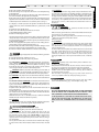
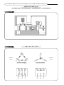
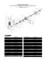
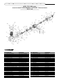
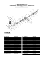
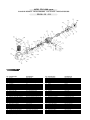
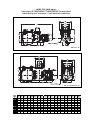
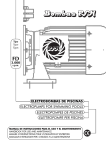
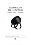
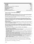
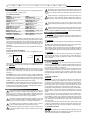
F
D
-
3
.
1. DESCRIPTION
1.1. These electropumps have been designed to recirculate lightly treated water in private and public swimming pools.
1.2. Technical characteristics
MOTOR:
Power rating: See motor plate.
Insulation: Class F.
Operation: Continuous.
Protection: IP 55.
Current: Triphase (see nameplate ratings).
Consumption: See motor plate.
Frecuency: See motor plate.
R.P.M.: See motor plate.
Shaft: Stainless steel.
Bearing: Amoured ball bearing.
Atmospheric temperature:
Minimum1ºC - Maximum 40ºC.
PUMP:
Water temperature:
Minimum1ºC - Maximum 40ºC.
Maximum pressure: 2,1 bar.
Impeller model: Closed.
Type of seal: Mechanical.
Impeller: Type FD
Pump casing: Type FD
Prefilter: Type FD
Basket: Stainless Steel.
Suction diameter: According to the
pump characteristics.
Delivery diameter: According to the
pump characteristics.
2. GENERAL
2.1. Introduction. This Handbook contains the instructions necessary for installation, use and maintenance of the swimming pool electropump. In order to
obtain the maximum performance shown in the Description of Characteristics,
it is necessary to fulfil and follow correctly all the recommendations given in
this-Handbook. This will allow operation with a safe and long-lasting piece of
equipment.
The equipment supplier will furnish the user with complementary information,
if required.
2.2. Safety signs used in the handbook
All instructions referring to possible risks to persons are highlighted by the following symbols:
Danger
in general
Standard DIN
4844-W9
Danger
of
electrocution
Standard DIN
4844-W8
Other instructions in relation to the functioning of the equipment with which
non-compliance could cause physical damages are highlighted with the warning: ATTENTION
2.3. Nameplate ratings (EEC 89/392 P.1.7.4.A). The information given on the
nameplate or other instructions affixed to the unit, must be strictly complied
with. The content of these plates can usually be found in this Handbook
(Chapter 1.2.).
2.4. Liability. Failure to comply with the instructions given by BOMBAS PSH
in this Handbook, in relation to the choice, handling, installation, starting and
maintenance of the unit, shall release the manufacturer or distributor from all
liability in respect of accidents suffered by persons or damages caused to other
installations and, in addition, shall entail forfait of the warranty.
2.5. Standards. Our swimming pool electropumps are manufactured in accordance with the necessary requeriments for safety and health set forth in
Community Directives 89/392/EEC,91/368/EEC (assimilated into Spanish Law
by Royal Decrees 1435/1992 and 93/44/EEC).
3. GENERAL INSTRUCTIONS IN RELATION TO USER SAFETY
3.1. Safety during operation of the machinery supplied can only be guaranteed if it is used in accordance with the diagrams show “Illustrations”. It must never exceed the working conditions and limits given in this
Handbook (Chapter 1.2. - Technical Characteristics). Compliance with the provisions of Safety Standards in force in each country is mandatory.
3.2. Please ensure that the equipment selected is adequate for the used
for witch it is intented and that its condition, installation, starting and
subsequent use are correct. See chapter 1.2. (Technical Characteristics).
3.3. Installation, repair and maintenance operations will be carried out
in all cases with the equipment disconnected from the mains.
3.4. While the equipment is functioning, it cannot be moved or repositioned. These operations will be carried out at all times with the machine disconnected.
0
0
0
3.5. Pressing of the electrical on/off or safety elements will not be performed where there is damp, and special care must be taken for user’s
hands to be dry, and also with footwear and surfaces with which the user is in
contact.
3.6. Those elements of the equipment which, when functioning, are in
movement or which could reach dangerous temperatures, will be protected with cages or casings which will prevent accidental contact with the same.
3.7. Electricity conductors, or parts which could carry current, will be
suitably insulated. Other metal parts of the equipment will be correctly
earthed.
3.8. Spare parts that may be necessary will be originals from the manufacturer or those recommended by the manufacturer. The use of others,
are not permitted and release the manufacturer or distributor from all liability.
4. PACKING, TRANSPORT AND STORAGE
4.1. ATTENTION.
The manufacturer supplies the equipment protected in suitable packaging, so
that it is not damaged during transport or storage thus ensuring its correct installation and/or functioning.
4.2. ATTENTION.
The user, upon receipt of the equipment, will immediately check the following
points:
l Condition of the outside packaging, if this shows signs of serious deterioration,
he shall formally advise the person delivering the equipment.
l He shall also check the condition of the contents; should this show defects
which would presumably prevent correct functioning, he shall also formally notify the supplier within a period not exceeding 8 days from the date of delivery.
4.3. ATTENTION
Storage conditions must ensure the optimum preservation of the equipment.
Due to its particular relevance, we must stress that very damp atmospheres or
others where extreme changes in temperatures (which cause condensation)
must be avoided.
5. INSTALLATION AND ASSEMBLY
5.1. Location. ATTENTION.
The place where the electropump is to be located must be dry. In all events,
there must be a drain in the floor as a prevention against flooding. If the pump
is to be located in a damp place, a ventilation system must be provided in order to prevent the formation of condensation.
In the case of very confined areas, cold air can reach a low temperature which
requires a ventilation system where by the it does not exceed 40ºC. It is important for there to be sufficient space to permit the motor block to be dismounted horizontally and the hair filter vertically (see minimum space diagram
in fig. 1).
5.2. Positions / Installation
ATTENTION
The equipment or set of motor pump, filter and selection valve, will be installed near the swimming pool at a distance of no more than 3 m, from the surface skimmers and preferably at a level of 0,5m (never more than 3m) below
the level of the water, in order to achieve its “under load” functioning. The selection valve junction, and its connection to the nozzle and other accessories
incorporated in the swimming pool will preferably be made in PVC pipe.
Pipe diameters will depend on flows. The maximum water speed advisable in
the pipes will be 1.2 m/s in suction and 2m/s in impulsion. In any event, the
diameter of the suction pipe must not be less than the diameter of the pump
nozzle.
The suction pipe must be perfectly watertight and must be installed with a
downward inclination, thus avoiding the formation of air pockets. In permanent installations, with the pump positioned at a higher level than that of the
water, it is advisable for the longest strech of the suction pipe to be below the
levels mentioned until it reaches the vertical pipe which coincides with the
pump suction line.
The suction pipe can be either rigid or flexible with a reinforced coil to avoid
contraction. In fixed installations, with the pump below the water level, a shutoff valve will be placed on the suction pipe and another on the header pipe.
5.3. Connection to the mains
ATTENTION
l In general terms, the electrical installation will fully comply with
the Regulations and Complementary Technical provisions applicable and will be performed by an authorised Installer.
It is obligatory to install a protection and operation switchboard which will
contain all necessary and recommended elements. In general terms, it will
contain:
a. General cut-off or unipolar switch.
b. Short-circuit and overload protection devices for motors.
c. 30mA differential high sensitivity switch.
d. Others for monitoring and control.
The electrical characteristics of the protection devices and their regulation will
comply with those for the motors to be protected and with the service conditions envisaged for these, and the instructions given by the manufacturer must
be followed (see nameplate).
l In the case of equipment with triphase motors, the motor winding interconnection bridges, must be suitably positioned (see figs. 2).
l Conductor inlets and outlets at the bushing box will have stuffings to ensure
the absence of damp and dirt, and will therefore have a sealed casing.
l Conductors will have suitable terminals for connection to the bushings.
6. STARTING
Before connecting the equipment to the mains, the following operations
will be carried out:
l Check that the electrical conditions are correct.
l Manually check that the motor pump is not jammed.
6.1. Pump priming. ATTENTION. “Avoid blind functioning of the electropump”. With the pump in the suction position (above the water level of the
swimming pool), before starting, remove the prefilter cover (66) (fig. 3) and
slowly fill with clean water up to the level of the aspiration nozzle. Close the
cover (66) again and take care that it is hermetically closed.
ATTENTION. With the pump below the swimming pool water level, always with the cover (66) hermetically closed, fill the pump by slowly opening the aspiration cut-off valve, with the header valve in the open position.
6.2. ATTENTION. The pump must not be started without the lumps and hair
filter (item 64) (fig. 3) since this could cause obstruction and would block the
system.
6.3. Direction of rotation. ATTENTION. Ensure that the motor shaft turns freely; do not start the pump if it is blocked. For this purpose, electropumps have
a groove at the end of the shaft, on the ventilator side, which permits it to be
turned manually using a screwdriver (fig. 1).
In triphase motors, the impeller (55) can be unscrewed if the motors starts in
the opposite direction.
Counter-rotation can even damage the mechanical seal. Start the motor for a
few seconds and check that the direction of rotation coincides with that indicated by the arrow on the ventilator cover.
Should this not be the case, it is absolutely necessary to advise the authorised
installer (invert the connections between two phases).
6.4. ATTENTION.
Check that the motor does not exceed the amperage indicated on the nameplate rating (120) (fig. 3); otherwise, regulate using the header valve.
7. MAINTENANCE / CONSERVATION
Before touching, disconnect the electricity supply.
7.1. ATTENTION. Regularly check and clean the basket (64).
To remove the basket, place the valves, and all other valves, in the “off”
position. Loosen the cover (66) of the prefilter (100), remove the basket
(64) and clean it under running water, “do not strike” to avoid its deterioration. To re-place the basket (64), introduce it gently, untill it is in its
original position. Correctly place the joint (65) of the cover (66) and grease with vaseline.
Do not place the basket (64) in chemicals. Please remember that changes
in position of the valves will be made at all times with the motor switched
off.
S
H
7.2. ATTENTION
If the pump is switched off for long periods of time, should there be a danger of frost, the pump casing (62) should be emptied, by losening the plug
(69)/(103) along with their O-ring seals. Before starting the pump, replace
the plug (69)/(103) and their O-ring seals. Fill the prefilter (100) with water and check with a screwdriver that the motor is not jammed. If the shaft
has seized up, call a qualified technician. In the event of the motor flooding, do not try to start it; call an electrician to dismount the motor in order to dry it.
8. DISMOUNTING
8.1. ATTENTION
Before performing any operation, all valves must be in the
“off” position: having checked this:
Disconnect the general electricity switch and the differential switch (this
must be done by an authorised specialist).
l Loosen and remove the supply cables on the connection box (26) (fig. 3).
l Release the aspiration and impulsion sleeves.
l Empty the pump.
l
8.2. ATTENTION
In order to dismount and assemble the electropump, please see the detail
drawing. (Fig. 3). In order to remove the motor from the hydraulic casing
(62), remove the four screws (45)(39)(52) and lever so as to separate one
part from the other one.
In order to dismount the impeller (55) hold the motor shaft (1) with the aid
of a clamp, while rotating the nut (57) to the left (anticlockwise) for models FD17, FD 18, FD 19, FD 20, FD 21, and FD 22, and to the right
(clockwise) for models FD 14, FD 15 and FD 16, with a wrench, thus releasing the impeller (55). In this way the mechanical seal (74) is released,
too.
9. ASSEMPLY
ATTENTION
“All parts to be assembly must be clean and in perfect condition for use”.
In order to assemble the pump:
l Assemble the mechanical seal (80). Press this (43) until its locates into
the space; the seal will have been lubricated with water beforehand.
l Assemble the impeller (55) on the shaft (1), affixing it with the key (57),
impeller washer (56) and impeller nut (57). In this way, the two halves of
the mechanical seal are joined.
l Fix the motor to the pump casing (62) by means means of the four
screws (63), impeller washer (56) and pump housing nut (107).
10. SPARE PARTS
To order any spare parts, indication must be given of the part, number
shown on the detail drawing (fig 3) and nameplate ratings (120).
WARNING:
ALL THE ADJUSTEMENTS THAT ARE MADE TO THE EQUIPMENT
MUST BE MADE BY THE AUTHORIZED TECNICAL SERVICE. IF NOT
THE GUARANTEE IS VOID AND WE ACCEPT RESPONSABILITY.
IF THE EQUIPEMENT IS USED FOR ANY OTHER MEANS THAN SPECIFIED BY THE MANUFACTURED, THE PROTECTION OF THE EQUIPMENT COULD FAIL, THEREFORE LOSING THE COVER OF GUARANTEE.
H
P
S
l
S
I
The supply will have neutral and earth wires.
The mains voltage must correspond to that shown on the nameplate rating
for the equipment.
l The earth wire to be used must be sufficient to take, without deterioration,
the current absorbed by the equipment (see nameplate).
l The mains earth wire will be connected electrically to all metal parts of the
equipment which should not be under current, but which could accidentally
be affected by the same and which are accessible to persons (see figs. 2).
l
A
L
B
G
M
N
O
E
B
D
F
-
3
.
0
0
0
MOD. FD-3.000 r.p.m.
ILUSTRACIONES - ILLUSTRATIONS - ILLUSTRATIONS - ILLUSTRAZIONI
Fig. 1
Fig. 2
T R I F A S I C O
Tensión
menor
Tensión
mayor
Conexión triángulo
Conexión estrella
MOD. FD-3.000 r.p.m.
PLANO DE DESPIECE - DETAIL DRAWING - VUE ECLATÉE - DISEGNO ESPLOSO
FD 14 - 15 - 16
120
100
Fig. 3
POS.
1
2
3
5
6
8
9
10
11
13
14
19
21
26
27
28
29
30
32
33
34
35
36
37
40
43
44
47
48
49
50
51
DENOMINACIÓN
Eje rotor
Cojinete motor lado bomba
Cojinete motor lado ventilador
Tapa motor lado ventilador
Carcasa estator
Ventilador
Espárrago cierre motor
Coraza ventilador
Tornillo tierra
Tuerca placa conexiones
Tornilllo placa conexiones
Tornillo caja conexiones
Prensa pasa cables
Placa conexiones trifásica
Puente placa conexiones
Caja conexiones trifásica
Pasa cables trifásico
Anillo retención cojinete lado vent.
Junta caja conexiones
Tapeta cojinete motor
Tornillo tapeta cojinete
Tornillo fijación coraza
Tapa motor lado bomba
Brida fijación ventilador
Prensaestopa completo
Retén motor lado bomba
Retén motor lado ventilador
Arandela placa conexiones
Soporte prensaestopa
Junta prensaestopa
Paragoteo
Tapa soporte
DENOMINATION
Shatf with rotor
Motor ball bearing pump side
Motor ball bearing fun side
Back motor cover
Motor case and winding
Fan
Motor screw
Fan cover
Ground screw
Terminal box nut
Terminal box screw
Terminal case screw
Press cable bolt three-phase
Terminal box three-phase
Terminal box bridges
Terminal box cover three-phase
Cable bolt three-phase
Ball bearing retention washer fan side
Terminal box gasket
Motor ball bearing cover
Ball bearing cover screw
Fan cover screw
Motor cover pump side
Fixing fan ring
Complete press cable
Motor seal pump side
Motor seal fan side
Terminal box washer
Press cable bracket
Press cable gasket
Throw-off-washer
Bracket cover
POS.
52
54
55
56
57
61
62
63
64
65
66
67
70
71
74
75
76
80
89
90
91
92
97
98
99
100
101
102
103
104
105
106
120
DENOMINACIÓN
Tornillo tapa soporte a motor
Chaveta
Turbina
Arandela turbina
Tuerca turbina
Junta cuerpo bomba
Cuerpo bomba
Espárrago cuerpo bomba
Cesta filtro
Junta tapa filtro
Tapa filtro
Palomilla filtro
Tapón purga bomba
Junta tapón purga bomba
Parte dinámica (sello mecánico)
Cara roce estática (sello mecánico)
Junta (sello necánico)
Sello completo
Contra brida impulsión
Junta brida impulsión
Tornillo brida impulsión
Tuerca tornillo brida impulsión
Junta filtro bomba
Espárrago filtro bomba
Tuerca espárrago filtro bomba
Cuerpo filtro
Tornillo de ojo palomilla
Pasador tornillo de ojo
Tapón desagüe filtro
Junta tapón desagüe filtro
Arandela espárrago filtro bomba
Espárrago palomilla
Placa características
DENOMINATION
Bracket screw
Key
Impeller
Impeller washer
Impeller nut
Pump housing gasket
Pump housing
Pump housing screw
Filter basket
Filter cover gasket
Filter cover
Filter thumb nut
Drain plug pump
Drain plug pump gasket
Shaft seal (rotating)
Shaft seal (stationary)
Shaft seal gasket
Complete shaft seal
Impulsion flange
Impulsion flange gasket
Impulsion flange screw
Impulsion flange nut
Filter housing gasket
Filter housing screw
Filter housing nut
Filter housing
Filter screw
Filter screw bolt
Filter drain plug
Filter drain plug gasket
Filter pump washer
Thumb screw
Characteristics card (plate)
D
F
-
3
.
0
0
0
MOD. FD-3.000 r.p.m.
PLANO DE DESPIECE - DETAIL DRAWING - VUE ECLATÉE - DISEGNO ESPLOSO
FD 17-18
120
44
67
Fig. 3
POS.
1
2
3
5
6
8
9
10
11
13
14
19
21
26
27
28
29
30
32
33
34
35
36
37
39
40
42
43
44
47
50
DENOMINACIÓN
Eje rotor
Cojinete motor lado bomba
Cojinete motor lado ventilador
Tapa motor lado ventilador
Carcasa estator
Ventilador
Espárrago cierre motor
Coraza ventilador
Tornillo tierra
Tuerca placa conexiones
Tornilllo placa conexiones
Tornillo caja conexiones
Prensa pasa cables
Placa conexiones trifásica
Puente placa conexiones
Tapa caja conexiones trifásica
Pasa cables trifásico
Anillo retención cojinete lado ventilador
Junta caja conexiones
Tapeta cojinete motor
Tornillo tapeta cojinete
Tornillo coraza ventilador
Tapa motor lado bomba
Brida fijación ventilador
FD-18 Tuerca espárrago cierre motor
Prensaestopa completo
FD-18 Tornillo de cáncamo
Retén motor lado bomba
Retén motor lado ventilador
Arandela placa conexiones
Paragoteo
DENOMINATION
Shatf with rotor
Motor ball bearing pump side
Motor ball bearing fan side
Back motor cover
Motor case and winding
Fan
Motor screw
Fan cover
Ground screw
Terminal box nut
Terminal box screw
Terminal case screw
Press cable bolt three-phase
Terminal box three-phase
Terminal box bridge
Terminal case cover three-phase
Cable bolt three-phase
Ball bearing retention washer fan side
Terminal box gasket
Motor ball bearing cover
Ball bearing cover screw
Fan cover screw
Motor cover side pump
Fixing fan ring
Motor nut screw
Complete press cable
Eyebolt screw
Motor seal pump side
Motor seal fan side
Terminal box washer
Throw-off-cover-washer
POS.
51
52
54
55
56
57
61
62
63
64
65
66
67
70
71
74
75
76
80
97
98
99
100
101
102
103
104
105
106
120
DENOMINACIÓN
Tapa soporte
Tornillo tapa soporte a motor
Chaveta
Turbina
Arandela turbina
Tuerca turbina
Junta cuerpo bomba
Cuerpo bomba
Espárrago cuerpo bomba
Cesta filtro
Junta tapa filtro
Tapa filtro
Palomilla filtro
Tapón purga bomba
Junta tapón purga
Parte dinámica (Sello mecánico)
Cara roce estática (Sello mecánico)
Junta (Sello mecánico)
Sello completo
Junta filtro bomba
Espárrago filtro bomba
Tuerca espárrago filtro bomba
Cuerpo filtro
Tornillo de ojo palomilla
Pasador tornillo de ojo
Tapón desagüe filtro
Junta tapón desagüe
Arandela espárrago filtro bomba
Espárrago palomilla filtro
Placa de características
DENOMINATION
Bracket cover
Bracket screw
Key
Impeller
Impeller washer
Impeller nut
Pump housing gasket
Pump housing
Pump housing screw
Filter basket
Filter cover gasket
Filter cover
Filter thumb nut
Drain plug pump
Pump drain plug gasket
Shaft seal (rotating)
Shaft seal (stationary)
Shaft seal gasket
Complete shaft seal
Filter housing gasket
Filter housing screw
Filter housing nut
Filter housing
Filter screw
Filter screw bolt
Filter drain plug gasket
Drain plug gasket
Filter pump washer
Thumb screw
Characteristics card
MOD. FD-3.000 r.p.m.
PLANO DE DESPIECE - DETAIL DRAWING - VUE ECLATÉE - DISEGNO ESPLOSO
FD 19
120
Fig. 3
POS.
1
2
3
5
6
8
9
10
11
13
14
19
21
26
27
28
29
30
32
33
34
35
36
37
39
40
42
43
44
47
DENOMINACIÓN
Eje rotor
Cojinete motor lado bomba
Cojinete motor lado ventilador
Tapa motor lado ventilador
Carcasa estator
Ventilador
Espárrago cierre motor
Coraza ventilador
Tornillo tierra
Tuerca placa conexiones
Tornilllo placa conexiones
Tornillo caja conexiones
Prensa pasa cables
Placa conexiones trifásica
Puente placa conexiones
Caja conexiones trifásica
Pasacables trifásico
Anillo ret. cojinete lado ventilador
Junta caja conexiones
Tapeta cojinete motor
Tornillo tapeta cojinete
Tornillo fijación coraza
Tapa motor lado bomba
Brida fijación ventilador
Tuerca espárrago cierre motor
Prensaestopa completo
Tornillo de cáncamo
Retén motor lado bomba
Retén motor lado ventilador
Arandela placa conexiones
DENOMINATION
Shatf with rotor
Motor ball bearing pump side
Motor ball bearing fan side
Back motor cover
Motor case and winding
Fan
Motor screw
Fan cover
Ground screw
Terminal box nut
Terminal box screw
Terminal case screw
Press cable bolt
Terminal box three-phase
Terminal box bridge
Terminal case three-phase
Cable bolt three-phase
Ball bearing retention washer fan side
Terminal box gasket
Motor ball bearing cover
Ball bearing cover screw
Fan cover screw
Motor cover pump side
Fixing fan ring
Motor nut screw
Complete press cable
Eyebolt screw
Motor seal pump side
Motor seal fun side
Terminal box washer
POS.
48
49
50
51
52
54
55
56
57
61
62
63
64
65
66
67
70
71
74
75
76
80
97
98
99
100
101
102
103
104
105
120
DENOMINACIÓN
Soporte prensaestopa
Junta prensaestopa
Paragoteo
Tapa soporte
Tornillo tapa soporte a motor
Chaveta
Turbina
Arandela turbina
Tuerca turbina
Junta cuerpo bomba
Cuerpo bomba
Espárrago cuerpo bomba
Cesta filtro
Junta tapa filtro
Tapa filtro
Palomilla filtro
Tapón purga bomba
Junta tapón purga bomba
Parte dinámica (Sello mecánico)
Cara roce estática (Sello mecánico)
Junta (Sello mecánico)
Sello completo
Junta filtro bomba
Espárrago filtro bomba
Tuerca espárrago filtro bomba
Cuerpo filtro
Tornillo de ojo palomilla
Pasador tornillo de ojo
Tapón desagüe filtro
Junta tapón desagüe
Arandela espárrago filtro bomba
Placa de características
DENOMINATION
Press cable bracket
Press cable gasket
Throw-off-washer
Bracket cover
Bracket screw
Key
Impeller
Impeller washer
Impeller nut
Pump housing screw
Pump housing
Pump housing screw
Filter basket
Filter cover gasket
Filter cover
Filter thumb nut
Drain plug pump
Drain plug pump gasket
Shaft seal (rotating)
Shaft seal (stationary)
Shaft seal gasket
Shaft seal complete
Filter housing gasket
Filter housing screw
Filter housing nut
Filter housing
Filter screw
Filter screw bolt
Filter drain plug
Drain plug gasket
Filter pump washer
Characteristics card
MOD. FD-3.000 r.p.m.
PLANO DE DESPIECE - DETAIL DRAWING - VUE ECLATÉE - DISEGNO ESPLOSO
FD 20 - 21 - 22
120
Fig. 3
POS.
1
2
3
5
6
8
10
11
13
14
19
21
26
27
28
29
30
32
33
34
35
36
37
40
42
43
44
45
46
47
48
DENOMINACIÓN
Eje rotor
Cojinete motor lado bomba
Cojinete motor lado ventilador
Tapa motor lado ventilador
Carcasa estator
Ventilador
Coraza ventilador
Tornillo tierra
Tuerca placa conexiones
Tornilllo placa conexiones
Tornillo caja conexiones
Prensa pasa cables
Placa conexiones trifásica
Puente placa conexiones
Caja conexiones trifásica
Pasacables trifásico
Anillo ret. cojinete lado ventilador
Junta caja conexiones
Tapeta cojinete motor
Tornillo tapeta cojinete
Tornillo fijación coraza
Tapa motor lado bomba
Brida fijación ventilador
Prensaestopa completo
Tornillo de cáncamo
Retén motor lado bomba
Retén motor lado ventilador
Tornillo tapa motor lado bomba
Tornillo tapa motor lado ventilador
Arandela placa conexiones
Soporte prensaestopa
DENOMINATION
Shatf with rotor
Motor ball bearing pump side
Motor ball bearing fan side
Back motor cover
Motor case and winding
Fan
Fan cover
Ground screw
Terminal box nut
Terminal box screw
Terminal case screw
Press cable bolt three-phase
Terminal box three-phase
Terminal box bridge
Terminal case three-phase
Cable bolt three-phase
Ball bearing retention washer fan side
Terminal box gasket
Motor ball bearing cover
Ball bearing cover screw
Fan cover screw
Motor cover pump side
Fixing fan ring
Complete press cable
Eyebolt screw
Motor seal pump side
Motor seal fun side
Screw motor cover pump side
Screw motor cover fun side
Terminal box washer
Press cable bracket
POS.
49
50
51
52
54
55
56
57
61
62
63
64
65
66
67
70
71
74
75
76
80
97
98
99
100
101
102
103
104
105
120
DENOMINACIÓN
Junta prensaestopa
Paragoteo
Tapa soporte
Tornillo tapa soporte a motor
Chaveta
Turbina
Arandela turbina
Tuerca turbina
Junta cuerpo bomba
Cuerpo bomba
Espárrago cuerpo bomba
Cesta filtro
Junta tapa filtro
Tapa filtro
Palomilla filtro
Tapón purga bomba
Junta tapón purga bomba
Parte dinámica (Sello mecánico)
Cara roce estática (Sello mecánico)
Junta (Sello mecánico)
Sello mecánico
Junta filtro bomba
Espárrago filtro bomba
Tuerca espárrago filtro bomba
Cuerpo filtro
Tornillo de ojo palomilla
Pasador tornillo de ojo
Tapón desagüe filtro
Junta tapón desagüe
Arandela espárrago filtro bomba
Placa de características
DENOMINATION
Press cable gasket
Throw-off-washer
Bracket cover
Bracket screw
Key
Impeller
Impeller washer
Impeller nut
Pump housing screw
Pump housing
Pump housing screw
Filter basket
Filter cover gasket
Filter cover
Filter thumb nut
Drain plug pump
Gasket drain plug pump
Shaft seal (rotating)
Shaft seal (stationary)
Shaft seal gasket
Complete shaft seal
Filter housing gasket
Filter housing screw
Filter housing nut
Filter housing
Filter screw
Filter screw bolt
Filter drain plug
Drain plug gasket
Filter pump washer
Characteristics card
MOD. FD-3.000 r.p.m.
CARACTERÍSTICAS Y DIMENSIONES - CHARACTERISTICS AND DIMENSIONS
CARACTERISTIQUES ET DIMENSIONS - CARATTERISTICHE E DIMENSIONI
FD 14-15-16
FD 17-18-19-20-21-22
BRIDA DE ASPIRACIÓN
Tipo
Type DNA Da
IA
KA
FD-14
FD-15
FD-16
FD-17
FD-18
FD-19
FD-20
FD-21
FD-22
80
80
80
100
100
125
125
125
125
200
200
200
220
220
250
250
250
250
160
160
160
180
180
210
210
210
210
BRIDA DE IMPULSION
DNI
DI
19 R2”GAS 19 R2”GAS 19 R2”GAS 19 100 220
19 100 220
19 100 220
19 100 220
19 100 220
19 100 220
K1
180
180
180
180
180
180
I1
19
19
19
19
19
19
A
383
383
383
420
420
466
466
466
466
B
62
62
62
76
72
72
173
173
173
C
84
84
84
84
112
112
140
140
178
D
144
144
144
144
176
176
216
216
216
DIMENSIONES EN mm
E
273
273
273
288
288
290
312
312
312
F
210
210
210
210
210
250
250
250
250
G
319
319
327
327
331
360
360
360
360
H1
120
120
128
128
132
132
132
132
132
H2
130
130
130
190
190
190
190
190
190
L
735
735
762
817
831
876
918
918
956
KG.
50
51.5
55.5
64
72
85
95
100
110