1
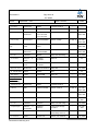
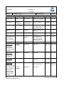
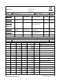
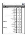
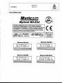
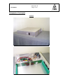
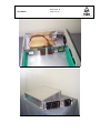
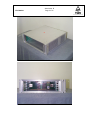
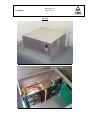
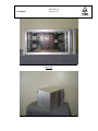
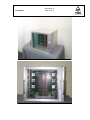
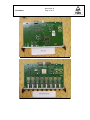
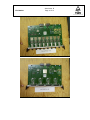
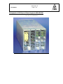
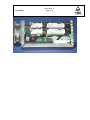
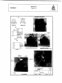
E2172805.01
Page 1 of 46
IEC 60950
TEST REPORT
IEC 60950
Safety of information technology equipment
Report Reference No...................... :
E2172805.01
Compiled by (+ signature) ............... :
Uwe Meyer
Approved by (+ signature)................ :
Keith Sinclair
Date of issue.................................. :
07/18/2001
Contents........................................ :
46
This report form was prepared by TÜV Rheinland using information obtained from the TRF I950___D/97-06 of TRF originator FIMKO.
This report is not valid as a CB Test Report unless appended to a CB Test Certificate issued by a NCB, in accordance with IECEE
02. This report shall not be reproduced except in full without the written approval of the testing laboratory.
Testing laboratory........................ :
TUV Rheinland of North America, Inc.
Address......................................... :
12 Commerce Road, Newtown, CT 06470
Testing location.............................. :
TUV Rheinland of North America, Inc.
Applicant Name ............................ :
Myricom, Inc.
Address......................................... :
325 N. Santa Anita Ave., Arcadia CA 91006
Test specification
IEC 60950:1991+A1:1992+A2:1993+A3:1995+A4:1996
Standard........................................ :
EN 60950:1992+A1+A2+A3+A4+A11
Test procedure .............................. :
CB scheme
Procedure deviation ........................ :
Group, AT, AU, BE, CA, CH, CN, CZ, DE, DK, ES, FI, FR, GB, GR, HU, IE,
IL, IN, IT, JP, KR, NO, NL, PL, RU, SE, SI, SK, US, ZA
Non-standard test method ............... :
N.A.
Test item ...................................... :
Modular Switches and Switch Networks
Trademark ..................................... :
Myrinet
Model and/or type reference ............ :
M3-E16, M3-E32, M3-E64, M3-E128
Manufacturer.................................. :
Myricom, Inc., 325 N. Santa Anita Ave., Arcadia CA 91006
Rating(s)........................................ :
100 – 127 Vac / 200 - 240 Vac, 50 / 60 Hz,
2.0 / 1.0 A (M3-E16), 3.0 / 1.5 A (M3-E32),
6.0 / 3.0 A (M3-E64), 12.5 / 6.25 A (M3-E128),
Test item particulars
Equipment mobility................................................. :
TÜV Rheinland TRF950_99-10
fixed equipment / rack mount
Doc. No.: R1109500.000, Rev.1, 10/99
E2172805.01
Page 2 of 46
IEC 60950
Operating condition................................................. :
continuous
Tested for IT power systems.................................... :
No
IT testing, phase-phase voltage (V)........................... :
-
Class of equipment ................................................. :
Class I
Mass of equipment (kg)........................................... :
7.6kg (M3-E16), 9.6kg (M3-E32),
(M3-E64), 21.2kg (M3-128)
Protection against ingress of water........................... :
IPX0
12.8kg
Test case verdicts
Test case does not apply to the test object............... :
N(.A.)
Test item does meet the requirement ....................... :
P(ass)
Test item does not meet the requirement .................. :
F(ail)
Short description of the unit:
The products as covered by this test report are ‘Modular Switches and Switch Networks’ with the model
designations ‘M3-E16, M3-E32, M3-E64, M3-E128’. All models are out of one model series and they are mostly
identical. All enclosures contain a metal chassis, one approved power supply (different for each model), approved
DC fans, a backplane, AC-Inlet/Filter and interface cards, which are all interchangeable. The backplanes of the –
E32, -E64 and –E128 include 16-port crossbar switches that form the ‘Spine of a Clos network’. The top slot is
reserved for a monitoring line card. The other slots accept port line cards with up to 8 ports on the front panel, and 8
SAN ports that connect to the backplane.
Model No. M3-E16 is a ‘2U high, 3 -slot enclosure for switches up to 16 ports’,
Model No. M3-E32 is a ‘3U high, 5 -slot enclosure for switch networks up to 32 ports’,
Model No. M3-E64 is a ‘5U high, 9 -slot enclosure for switch networks up to 64 hosts’,
Model No. M3-E128 is a ‘9U high, 17-slot enclosure for switch networks up to 128 ports’,
There are no connections to a Telecommunication Network (TNV). The equipment is rated for a maximum ambient
temperature of 40ºC.
CDRH-Report for Optical Transceiver has to be provided by customer for US Approval.
attachments are numbered : X - Y/Z
X : attachment no.
Y : page no.
Z : total no. of pages in the attachment
Attachments:
Abbreviations: pri.
: primary
sec.
: secondarygnd. : ground
PE
: protective earth
SWPS : Switching power supply
HV
: high voltage
*)
: covered by certified power supplies
Attachment
Attachment
Attachment
Attachment
A: Copy of Rating Labels
B: Photographs of test sample
C: Copy of CB-Cert. for Power Supplies
D: Photographs of AC/DC part of power
supply for M/N: M3-E128 (‘Power One’,
M/N: HPF3BCB1YE
Attachment E: Transformer Spec. for (T1)
TÜV Rheinland TRF950_99-10
Doc. No.: R1109500.000, Rev.1, 10/99
E2172805.01
Page 3 of 46
IEC 60950
Clause
Requirement − Test
1
GENERAL
P
1.5
Components
P
1.5.1
Comply with IEC 60950 or relevant component
standard
1.5.2
Evaluation and testing of components
Result - Remark
(see appended table)
All safety critical components
are certified, all components
are used within their rating,
PCBs and wiring material are
UL listed, non-certified
components were tested
according this standard
Verdict
P
P
Dimensions (mm) of mains plug for direct plug-in . :
N
Torque and pull test of mains plug for direct
plug-in; torque (Nm); pull (N)
N
1.5.3
Transformers
1.5.4
High voltage components (component;
Not Applicable
manufacturer; flammability) ................................ :
N
1.5.5
Interconnecting cables
Signal cables only used which
carry no hazardous potentials
or energy levels
P
1.5.6
Mains capacitors
All X capacitors are according
to IEC 384-14 or part of
certified power supplies
P
1.6
Power interface
1.6.1
Steady state input current
M3-E16:
1.77A (90Vac),
0.74A (208Vac)
M3-E32: 2.70A (90Vac),
1.15A (208Vac)
M3-E64: 4.35A (90Vac),
1.81A (208Vac)
M3-E128: 12.32A (90Vac),
5.08A (208Vac)
P
Current deviation during normal operating cycle
< 10%
P
TÜV Rheinland TRF950_99-10
According to Annex C (T1 of
‘HPF3 Bias Board’ of power
supply for M/N: ‘M3-128’; other
transformers are part of
certified power supplies
P
P
E2172805.01
Page 4 of 46
IEC 60950
Clause
Requirement − Test
Result - Remark
1.6.2
Voltage limit of hand-held equipment
no hand held device
N
1.6.3
Neutral conductor insulated from earth and body
Neutral is isolated by basic
insulation (BI) from PE at ACInlet/Filter and within approved
power supplies
P
1.6.4
Components in equipment intended for IT power
system
All Y-caps are approved
components according to IEC
384-14
P
1.6.5
Mains supply tolerance (V) ................................ : Tested at +6/-10%:
Verdict
P
90 - 254V
1.7
Marking and instructions
P
1.7.1
Rated voltage (V) .............................................. : AC 100-127 V / 200–240V
P
Symbol of nature of supply for d.c. ..................... : AC input
N
Rated frequency (Hz) ........................................ : 50 / 60 Hz
P
Rated current (A) .............................................. :
2.0 / 1.0 A (M3-E16),
3.0 / 1.5 A (M3-E32),
6.0 / 3.0 A (M3-E64),
12.5 / 6.25 A (M3-E128)
P
Manufacturer .................................................... : Myricom, Inc.
P
Trademark ....................................................... : Myrinet
P
Type/model ...................................................... : M3-E16, M3-E32, M3-E64, M3E128
P
Symbol of Class II ............................................ : class I product
N
Certification marks ............................................ : ‘cTUVus’, other marks to be
provided
P
1.7.2
Safety instructions
P
1.7.3
Short duty cycles
N
1.7.4
Marking for voltage setting/frequency setting ....... : No adjustments to be done,
power supplies are autoranging
P
1.7.5
Marking at power outlets ................................... : No power outlets
N
1.7.6
Marking at fuseholders ...................................... : None accessible to operator
N
1.7.7.1
Protective earthing terminals
P
TÜV Rheinland TRF950_99-10
User Manual explains safe
operation
Not required, PE supplied
through certified inlet, PE
ground connection to enclosure
E2172805.01
Page 5 of 46
IEC 60950
Clause
Requirement − Test
Result - Remark
Verdict
via chassis
1.7.7.2
Terminal for external primary power supply
conductors
detachable power cord
N
1.7.8.1
Identification and location of switches and controls No switches and controls, only
........................................................................ : ‘status’-LEDs at front of cards
which are not safety relevant
N
1.7.8.2
Colours of controls and indicators ...................... : Green LEDs used for status
indication
P
1.7.8.3
Symbols according to IEC 417 ........................... : Ground symbol according to
IEC 417, No. 5019
P
1.7.8.4
Figures used for marking ................................... : No figures used
N
1.7.8.5
Location of markings and indications for switches No switches and controls
and controls ..................................................... : used, no markings provided
N
1.7.9
Isolation of multiple power sources ..................... : single power source only
N
1.7.10
Instructions for installation to IT power system
EUTs not verified for IT power
connection
N
1.7.11
Instructions when protection relies on building
installation
pluggable type A connection
via appliance inlet, no special
requirements
N
1.7.12
Marking when leakage current exceeds 3,5 mA
No excessive leakage current
measured
N
1.7.13
Indication at thermostats and regulating devices
No such devices used
N
1.7.14
Language of safety markings/instructions
Safety markings / Instructions
provided in users manual
P
Language ......................................................... : English
-
1.7.15
Durability and legibility
Meets rubbing test, UL
approved label system; ground
symbols are engraved in to the
metal chassis
P
1.7.16
Removable parts
see 1.7.14
N
1.7.17
Warning text for replaceable lithium batteries
No lithium batteries used
N
1.7.18
Language ......................................................... :
-
Operator access with a tool ............................... : No operator access to any
internal areas which contain
hazardous voltages; once
cards have been removed,
operator has access to SELV
N
TÜV Rheinland TRF950_99-10
E2172805.01
Page 6 of 46
IEC 60950
Clause
Requirement − Test
Result - Remark
Verdict
areas only, no tools required
1.7.19
Equipment for restricted access locations ........... : EUT is not considered for
exclusive usage in restricted
access locations
N
2
PROTECTION FROM HAZARDS
P
2.1
Protection against electric shock and energy hazards
P
2.1.1
Access to energized parts
No access
P
2.1.2
Protection in operator access areas
Adequate protection by
enclosure. There is no access
to hazardous parts.
P
2.1.3.1
Test by inspection ............................................ : Protection is established by
insulation materials
P
Test with test finger .......................................... : No access to above mentioned
parts
P
Test with test pin .............................................. : No access to above mentioned
parts
P
Insulation of internal wiring in an ELV circuit
accessible to operator
N
No ELV accessible
Working voltage (V); distance (mm) through
insulation ......................................................... :
N
2.1.3.2
Operator accessible insulation of internal wiring at
hazardous voltage
Not accessible
N
2.1.4.1
Protection in service access areas
No unexpected hazards inside
the unit, no unintentional
contact to hazardous areas
likely, SWPSs are covered
P
2.1.4.2
Protection in restricted access locations
Not applied
N
2.1.5
Energy hazard in operator access area
No energized parts remain
once power is disconnected
P
2.1.6
Clearances behind conductive enclosures
No reduction below limits or
deformation possible which is
safety relevant
P
2.1.7
Shafts of manual controls
None provided
N
2.1.8
Isolation of manual controls
see 2.1.7
N
2.1.9
Conductive casings of capacitors
Conductive casings of
capacitors considered of the
P
TÜV Rheinland TRF950_99-10
E2172805.01
Page 7 of 46
IEC 60950
Clause
Requirement − Test
Result - Remark
Verdict
capacitors considered of the
same potential as the pins
within approved power supplies
2.1.10
Risk of electric shock from stored charge on
capacitors connected to mains circuit
No hazards, measured at
254Vac
P
Time-constant (s); measured voltage (V) ............. : M3-E16: 6.5V after 1 sec.
(‘Power One’), 6.7V after 1
sec. (‘Astec’-power supply)
M3-E32: 19.0V after 1 sec.
M3-E64: 0.4V after 1 sec.
M3-E128: 0.3V after 1 sec.
-
2.2
Insulation
P
2.2.1
Methods of insulation
Insulation established through
creepage and clearance
distances and through certified
power supplies
P
2.2.2
Properties of insulating materials
Insulation materials are
adequately selected
P
No hygroscopic materials
2.2.3
Humidity treatment
Humidity treatment performed
on ‘Power One’ power supply
P
Other employed materials are
not susceptible to humidity
Humidity (%) .................................................... : 95%RH
-
Temperature (ºC) .............................................. : 28ºC
-
2.2.4
Requirements for insulation
Insulation provided met all
requirements and passed
electric strength tests (see
also 2.9, 5.1 and 5.3)
P
2.2.5
Insulation parameters
Considered
P
2.2.6
Categories of insulation
Basic insulation between
primary and ground/ reinforced
or double insulation between
primary and secondary/ from
hazardous voltages to the
operator and to unearthed
conductive parts / operational
insulation between the lines
ahead of the fuse
P
TÜV Rheinland TRF950_99-10
E2172805.01
Page 8 of 46
IEC 60950
Clause
Requirement − Test
Result - Remark
Verdict
2.2.7.1
General rules for working voltages
(results see 2.9)
P
2.2.7.2
Clearances in primary circuits
Within approved power
supplies and between primary
of power supplies and
secondary wiring
P
2.2.7.3
Clearances in secondary circuits
SELV only, no special
requirements
P
2.2.7.4
Creepage distances
Refer to appended table
P
2.2.7.5
Electric strength tests
See table 5.3
P
2.2.8.1
Bridging capacitors ........................................... : Approved power supplies
N
2.2.8.2
Bridging resistors
Approved power supplies
N
2.2.8.3
Accessible parts
No such components
N
2.3
Safety extra-low voltage (SELV) circuits
P
2.3.1
Voltage (V) of SELV circuits under normal
12V maximum from the
operating conditions and after a single fault ......... : certified power supplies
-
2.3.2
Voltage (V) between any two conductors of SELV 12V maximum from the
circuit(s) and for Class I equipment between any
certified power supply
conductor of SELV circuit and equipment
protective earthing terminal under normal operating
conditions ........................................................ :
P
2.3.3
Voltage (V) of SELV in the event of a single failure <42.4VAC or 60VDC,
of basic or supplementary insulation or of a
compliance based on
component ....................................................... : certification of SWPS
-
Method used for separation ............................... : Method 1
P
2.3.4
Additional constructional requirements
P
2.3.5
Connection of SELV circuits to other circuits
2.4
Limited current circuits
N
2.4.2
Frequency (Hz) ................................................ :
-
Measured current (mA) ..................................... :
N
Measured voltage (V) ........................................ :
-
Measured capacitance (ºF) ................................ :
N
Measured voltage (V) ........................................ :
-
Measured charge (ºC) ....................................... :
N
2.4.3
2.4.4
TÜV Rheinland TRF950_99-10
Only SELV type interfaces
P
E2172805.01
Page 9 of 46
IEC 60950
Clause
Requirement − Test
2.4.5
Measured voltage (V) ........................................ :
-
Measured energy (mJ) ...................................... :
N
2.4.6
Limited current circuit supplied from or connected
to other circuits ................................................ :
N
2.5
Provisions for earthing
P
2.5.1
Class I equipment
Result - Remark
PE connection through
earthing pin of appliance inlet
via GRN/YLW-wire to chassis.
The ground wire is connected
to the chassis by a dedicated
stud using ring-lug first,
starwasher and nut. On top of
that the ground wire of the
power supply is connected
using another starwasher and
nut.
Warning label for service personnel
Verdict
P
N
2.5.2
Protective earthing in Class II equipment
Class I equipment
N
2.5.3
Switches/fuses in earthing conductors
None
P
2.5.4
Assured earthing connection for Class I equipment Class I equipment only
in systems comprising Class I and Class II
equipment
N
2.5.5
Green/yellow insulation
Only GRN/YLW-wire is used
P
2.5.6
Continuity of earth connections
None
N
2.5.7
Making and breaking of protective earthing
connections
Approved AC-inlet is used
P
2.5.8
Disconnection protective earthing connections
PE does not have to be
disconnected for servicing
P
2.5.9
Protective earthing terminals for fixed supply
conductors or for non-detachable power supply
cords
2.5.10
Corrosion resistance
Table 1 of Annex J consid.
P
2.5.11
Resistance (Ohm) of protective earthing
conductors < 0,1 Ohm
Resistance measured after 120
sec. from PE at appl. inlet to
chassis:
P
N
M3-E16: 21.78mOhm
M3-E32: 22.74mOhm
TÜV Rheinland TRF950_99-10
E2172805.01
Page 10 of 46
IEC 60950
Clause
Requirement − Test
Result - Remark
Verdict
M3-E64: 17.01mOhm
M3-E128: 17.57mOhm
Test current (A) ................................................ : 30
-
2.6
Disconnection from primary power
P
2.6.1
General requirements
2.6.2
Type of disconnect device ................................. : Provided appliance inlet
P
2.6.3
Disconnect device in permanently connected
equipment
N
2.6.4
Parts of disconnect device which remain energized No parts remain energized after
disconnect
N
2.6.5
Switches in flexible cords
none
N
2.6.6
Disconnection of both poles simultaneously in
single-phase equipment
with appliance inlet, certified
inlet
P
2.6.7
Disconnection of all phase conductors of supply in single phase equipment
three-phase equipment
N
2.6.8
Marking of switch acting as disconnect device
Switch not used
N
2.6.9
Installation instructions if plug on power supply
cord acts as disconnect device
Not required
N
Approved Appliance Inlet
not permanently connected
Language ......................................................... :
P
-
2.6.11
Interconnected equipment
No groups present
N
2.6.12
Multiple power sources
single power source
N
2.7
Overcurrent and earth fault protection in primary circuits
P
2.7.1
Basic requirements
Earth fault protection is
assumed to be provided by
building installation.
P
2.7.2
Protection against faults not covered in 5.4
Fault protection provided by
approved power supplies
P
2.7.3
Short-circuit backup protection
No additional means of
protection needed for
compliance to requirements of
this standard
N
2.7.4
Number and location of protective devices ........... : Power supplies are provided
with short circuit current
protection by one fuse in one
line, earth fault protection by
TÜV Rheinland TRF950_99-10
P
E2172805.01
Page 11 of 46
IEC 60950
Clause
Requirement − Test
Result - Remark
Verdict
building installation
2.7.5
Protection by several devices
Fuse is single component
P
2.7.6
Warning to service personnel
No unexpected hazard
N
2.8
Safety interlocks
2.8.2
Design
2.8.3
Protection against inadvertent reactivation
2.8.4
Reliability
2.8.5
Overriding an interlock
N
2.8.6.1
Contact gap (mm) ............................................. :
N
2.8.6.2
Switch performing 50 cycles
N
2.8.6.3
Electric strength test: test voltage (V) ................. :
N
2.8.7
Protection against overstress
P
2.9
Clearances, creepage distances and distances through insulation
P
Nominal voltage (V) ........................................... : Actual working voltage applied,
but not less than the supply
voltage of 240Vac
-
General
P
2.9.2
Clearances
P
2.9.2.1
Clearances in primary circuits
(see table 2.9.2 and 2.9.3)
P
2.9.2.2
Clearances in secondary circuits
(see table 2.9.2 and 2.9.3)
P
2.9.3
Creepage distances
(see table 2.9.2 and 2.9.3)
P
N
None required – none provided
N
N
CTI tests .......................................................... : None performed, class IIIb was
assumed for all tests
-
2.9.4.1
Minimum distances through insulation
RI provided in Certified power
supplies which is the only
necessity for RI;
supplementary insulation in
form of sleeving on secondary
wiring touching primary (-wiring
at AC-inlets): min. distance
0.4mm
P
2.9.4.2
Thin sheet material
Isolation transformer is part of
approved SWPS’s
N
TÜV Rheinland TRF950_99-10
E2172805.01
Page 12 of 46
IEC 60950
Clause
Requirement − Test
Result - Remark
Verdict
approved SWPS’s
2.9.4.3
2.9.4.4
2.9.5
Number of layers (pcs) ...................................... :
N
Electrical strength test: test voltage (V) .............. :
N
Printed boards
Not used for supplementary or
reinforced insulation
Distance through insulation
N
Electric strength test at voltage for thin sheet
insulating material
N
Number of layers (pcs) ...................................... :
N
Wound components without interleaved insulation
None provided
2.9.7
N
Number of layers (pcs) ...................................... :
N
Two wires in contact inside component;
angle between 45º and 90º
N
Routine testing for finished component
N
Distances on coated printed boards
Not used
Routine testing for electric strength
2.9.6
N
Enclosed and sealed parts
N
N
No hermetically sealed
components; approved power
supplies used
N
Temperature T1 (ºC) .......................................... :
N
Humidity % ...................................................... :
N
Spacings filled by insulating compound
No insulating compound is
used to fill BI and SI
N
Temperature T1 (ºC) .......................................... :
N
Humidity % ...................................................... :
N
2.9.8
Component external terminations
(see appended table 2.9.2 and
2.9.3)
P
2.9.9
Insulation with varying dimensions
considered in approved power
supplies
P
2.10
Interconnection of equipment
2.10.1
General requirements
2.10.2
Type of interconnection circuits .......................... : See above
TÜV Rheinland TRF950_99-10
P
SELV signal connections only
P
P
E2172805.01
Page 13 of 46
IEC 60950
Clause
Requirement − Test
Result - Remark
2.10.3
ELV circuits as interconnection circuits
No ELV connections
2.11
Limited power source
N
Use of limited power source ............................... : not used
N
3
WIRING, CONNECTIONS AND SUPPLY
P
3.1
General
P
3.1.1
Cross-sectional area of internal
wiring/interconnecting cables
Sufficiently rated wiring for AC
distribution
P
Protection of internal wiring and interconnecting
cables
Sufficiently protected by
primary fuse and over current
protection circuits
P
3.1.2
Wireways
Wires are clamped and routed
to avoid exposure to
mechanical or thermal stress
P
3.1.3
Fixing of internal wiring
Reliable by double crimped
providing double restraint.
Other connectors are insulation
crimp type
P
3.1.4
Fixing of uninsulated conductors
10 N applied to all uninsulated
conductors like the pins of
components
P
3.1.5
Insulation of internal wiring
inspected
P
3.1.6
Wires coloured green/yellow only for protective
earth connection
3.1.7
Fixing of beads and similar ceramic insulators
No beads or similar insulators
used; approved power supplies
provided
N
3.1.8
Required electrical contact pressure
No contact pressure through
insulation material
N
3.1.9
Reliable electrical connections
Reliable connection, contact
pressure is not transmitted
through insulating materials
P
3.1.10
End of stranded conductor
No contact pressure on
stranded wire
N
3.1.11
Use of spaced thread screws/thread-cutting
screws
None used
N
TÜV Rheinland TRF950_99-10
Verdict
N
P
E2172805.01
Page 14 of 46
IEC 60950
Clause
Requirement − Test
Result - Remark
Verdict
screws
3.2
Connection to primary power
P
3.2.1
Type of connection ........................................... : Detachable power cord,
pluggable equipment type A
P
Design of product with more than one supply
connection ....................................................... :
N
Provision for permanent connection .................... : no means for permanent
connections provided
N
Size (mm) of cables and conduits ...................... :
N
3.2.2
3.2.3
Appliance inlet
Certified AC-inlet/Filters are
used (IEC 320)
3.2.4
Type and cross-sectional area (mm²) of power
Power cords are distributed for
supply cord ...................................................... : various countries, refer to list of
critical components for details
P
3.2.5
Cord anchorage
N
Test: 25 times; 1 s; pull (N) ............................... : detachable power cord
-
Longitudinal displacement < 2 mm ..................... :
N
detachable power cord
P
3.2.6
Protection of power supply cord
3.2.7
Cord guard
N
D (mm) ............................................................ : detachable power cord
-
Test: mass (g) .................................................. : detachable power cord
-
Radius of curvature of the cord > 1,5 D
-
3.2.8
Supply wiring space
3.3
Wiring terminals for external power supply conductors
N
3.3.1
Terminals
N
3.3.2
Special non-detachable cord
N
Type of connection ........................................... :
-
Pull test at 5 N
N
3.3.3
Screws and nuts
N
3.3.4
Fixing of conductors
N
3.3.5
Connection of connectors
N
TÜV Rheinland TRF950_99-10
detachable power cord
N
detachable power cord
N
E2172805.01
Page 15 of 46
IEC 60950
Clause
Requirement − Test
3.3.6
Size of terminals
N
Nominal thread diameter (mm) ........................... :
N
3.3.7
Protection against damage of conductors
N
3.3.8
Terminal location
N
3.3.9
Test with 8 mm stranded wire
N
4
PHYSICAL REQUIREMENTS
P
4.1
Stability and mechanical hazards
P
4.1.1
Stability tests
N
Angle of 10º
Result - Remark
no tilting or overbalancing
Verdict
P
Test: force (N) .................................................. : not floor standing
N
4.1.2
Protection against personal injury
P
4.1.3
Warning and means provided for stopping the
moving part ...................................................... :
4.1.4
Edges and corners
No sharp edges or similar
hazards
P
4.1.5
Enclosure of a high pressure lamp
no such component
N
4.2
Mechanical strength and stress relief
P
4.2.1
General
P
4.2.2
Internal enclosures 30 N ± 3 N; 5 s
Internal enclosures of approved
power supplies
N
4.2.3
External enclosures 250 N ± 10 N; 5 s
No damage or increased
accessibility to hazardous
potentials
P
4.2.4
Steel ball tests
no moving parts
N
P
Fall test
Metal enclosure with sufficient
spacing
P
Swing test
Metal enclosure with sufficient
spacing
P
4.2.5
Drop test
not hand-held
N
4.2.6
Heat test for enclosures of moulded or formed
Metal enclosure
thermoplastic materials: 7 h; T (ºC) .................... :
TÜV Rheinland TRF950_99-10
N
E2172805.01
Page 16 of 46
IEC 60950
Clause
Requirement − Test
Result - Remark
4.2.7
Compliance criteria
No hazards
P
4.2.8
Mechanical strength of cathode ray tubes
none provided
N
4.3
Construction details
4.3.1
Changing of setting for different power supply
voltages
Autoranging power supplies
used
N
4.3.2
Adjustment of accessible control devices
None provided
N
4.3.4
Prevention of dangerous concentration of dust,
powder, liquid and gas
No dust generated inside, no
connections to liquids or gases
N
4.3.5
Fixing of knobs, grips, handles, levers
N
Test: force (N) .................................................. : none provided
N
4.3.6
Driving belts/couplings shall not ensure electrical
insulation
none provided
N
4.3.7
Retaining of sleeves
No safety relevant sleeving
N
4.3.9
Protection of loosening parts
Screws, wires and the like are
adequately fixed
P
4.3.11
Resistance to oil and grease
no such materials inside
N
4.3.12
Protection against harmful concentration of
ionizing radiation, ultraviolet light, laser or
flammable gases (for laser see IEC 60825-1)
Optical transceiver is approved
component and of ‘class I’,
refer to list of critical
components for further details
P
4.3.13
Securing of screwed connections
Power supplies connected to
chassis with screws
P
4.3.15
Openings in the top of enclosure
None
N
4.3.16
Verdict
P
Dimensions (mm) ............................................. :
-
Openings in the sides of enclosure
P
Dimensions (mm) ............................................. : Vent opening(s) at right and left
side of each unit, vents are
separated for power supply and
interface cards, 4.7mm holes
on vent areas:
-
M3-E16: 2 x (65 x 65) mm and
2 x (185 x 65) mm
M3-E32: 2 x (99 x 104) mm
and 2 x (99 x 188) mm
M3-E64: 2 x (190x187) mm
TÜV Rheinland TRF950_99-10
E2172805.01
Page 17 of 46
IEC 60950
Clause
Requirement − Test
Result - Remark
Verdict
and 2 x (65 x 98) mm
M3-E128: 2 x (130x374) mm
and 2 x (138 x 129) mm
4.3.17
Interchangeable plugs and sockets
4.3.18
Torque test for direct plug-in equipment
N
Additional torque (Nm) ...................................... : no built-in plug used
N
4.3.19
Protection against excessive pressure
No pressure generated inside
N
4.3.20
Protection of heating elements in Class I
equipment
No intentional heating
elements inside
N
4.3.21
Protection of lithium batteries
N
Construction of protection circuit ........................ : No lithium batteries used
P
Ageing of barrier/screen secured with adhesive
N
Day 1: temperature (ºC); time (weeks) ................ : Safety relevant barriers are not
solely secured by adhesives
N
Day 8/22/57:
a) temperature (ºC) for 1 h
b) temperature (ºC) for 4 h
c) temperature (ºC) over 8 h ............................... :
N
Day 9/23/58:
a) relative humidity (%) for 72 h
b) temperature (ºC) for 1 h
c) temperature (ºC) for 4 h
d) temperature (ºC) over 8 h ............................... :
N
4.4
Resistance to fire
P
4.4.1
Methods of achieving resistance to fire
No excessive temperatures; no
easily burning materials
employed; fire enclosure
provided
P
4.4.2
Minimizing the risk of ignition
Risk reduced to minimum due
to appropriate flame rating of
employed materials and
components
P
Printed board: manufacturer; type; flammability ... : All PCB’s have flammability of
94V-0
P
4.4.3
Flammability of materials and components
P
4.4.3.2
Material and component: manufacturer; type;
See parts list
flammability ..................................................... :
4.3.22
TÜV Rheinland TRF950_99-10
Special shape of connectors
V-2 or better
P
P
E2172805.01
Page 18 of 46
IEC 60950
Clause
Requirement − Test
Result - Remark
Verdict
flammability ..................................................... :
4.4.3.3
Exemptions ..................................................... :
N
4.4.3.4
Wiring harnesses: manufacturer; flammability ..... : Wires VW-1 or PVC
P
4.4.3.5
Cord anchorage bushings: manufacturer;
None provided
flammability ..................................................... :
N
4.4.3.6
Air filter assemblies: manufacturer; flammability .. : None provided
N
4.4.4
Enclosures and decorative parts: manufacturer;
No decorative parts, metal
type; flammability ............................................. : enclosure only
P
4.4.5
Conditions for fire enclosures
P
4.4.5.1
Components requiring fire enclosure: manufacturer; Fire enclosure provided
flammability ..................................................... :
P
4.4.5.2
Components not requiring fire enclosure ............. :
N
4.4.6
Fire enclosure construction
no bottom openings, no
burning or molten material can
fall outside the fire enclosure
P
4.4.7
Doors or covers in fire enclosures
None
N
4.4.8
Flammable liquids
No liquids inside
N
5
THERMAL AND ELECTRICAL REQUIREMENTS
P
5.1
Heating
P
Heating tests
(see appended table)
P
5.2
Earth leakage current
5.2.1
General
(according Annex D)
P
5.2.2
Leakage current
No excessive leakage current
measured
P
5.2.3
P
Test voltage (V) ................................................ : 254V, 60Hz
-
Measured current (mA) ..................................... : M3-E16: 0.076mA (Power
One), 0.099mA (Astec)
M3-E32: 0.099 mA
M3-E64: 0.280 mA
M3-E128: 0.790 mA
-
Max. allowed current (mA) ................................. : 3.5 mA
-
Single-phase equipment
P
TÜV Rheinland TRF950_99-10
considered
E2172805.01
Page 19 of 46
IEC 60950
Clause
Requirement − Test
5.2.4
Three-phase equipment
N
5.2.5
Equipment with earth leakage current exceeding
3,5 mA
N
Cross-sectional area (mm²) of internal protective
earthing conductor ............................................ :
-
Warning label
N
5.3
Electric strength
P
5.3.1
General
P
5.3.2
Test procedure
5.4
Abnormal operating and fault conditions
5.4.2
Motors
Fan(s) – (a) blocked and (b)
disconnected (already
approved fans used)
P
5.4.3
Transformers
(T1) of ‘HPF3 Bias Board’ of
power supply for M/N: M3E128 was tested according to
Annex C, other transformers
are part of certified power
supplies
P
5.4.4
Compliance of operational insulation
P
Method used .................................................... : Method a)
P
5.4.5
Electromechanical components in secondary
circuits
None present
N
5.4.6
Other components and circuits
Part of certified power supplies
P
5.4.7
Test in any expected condition and foreseeable
misuse
Ventilation openings closed: no
unacceptable overheating of
parts
P
5.4.8
Unattended use of equipment having thermostats,
temperature limiters etc.
Thermal Switch (S1) is
approved component
P
5.4.9
Compliance
no hazards noted
P
5.4.10
Ball-pressure test of thermoplastic parts;
impression shall not exceed 2 mm
approved appliance inlet used,
AC connectors or terminal
blocks on power supplies are
part of approved power supplies
N
TÜV Rheinland TRF950_99-10
Result - Remark
(see appended table)
Verdict
P
P
E2172805.01
Page 20 of 46
IEC 60950
Clause
Requirement − Test
6
CONNECTION TO TELECOMMUNICATION NETWORKS
N
6.1
General
N
6.2
TNV circuits
N
6.2.1.1
Limits of the TNV circuits
N
6.2.1.1 a)
TNV-1 circuits
No TNV circuits
N
6.2.1.1 b)
TNV-2 and TNV-3 circuits
No TNV circuits
N
6.2.1.2
Separation from other circuits and from accessible No TNV circuits
parts
N
Voltage (V) in SELV circuits, TNV-1 circuits and
accessible conductive parts in event of single
insulation fault or component failure .................... :
N
6.2.1.3
6.2.1.4
6.2.1.5
6.2.2.1
Operating voltages generated externally
Result - Remark
No TNV circuits
Verdict
N
Voltage (V) in SELV circuit, TNV-1 circuit or
accessible conductive part ................................ :
N
Separation from hazardous voltages ................... : No TNV circuits
N
Insulation between TNV circuit and circuit at
hazardous voltage
N
Method used .................................................... :
N
Connection of TNV circuits to other circuits
N
Insulation (mm) between TNV circuit supplied
conductively from secondary circuit and hazardous
voltage circuit ................................................... :
N
Protection against contact with bare conductive
parts of TNV-2 and TNV-3 circuits
No TNV circuits
N
Test with test finger
N
Test with test probe
N
Battery compartments
N
Marking next to door/on door
N
6.3
Protection of telecommunication network service personnel, and users of other
equipment connected to the telecommunication network, from hazards in the
equipment
N
6.3.1
Protection from hazardous voltages
N
6.2.2.2
TÜV Rheinland TRF950_99-10
No TNV circuits
E2172805.01
Page 21 of 46
IEC 60950
Clause
Requirement − Test
6.3.2
Use of protective earthing
N
Language of installation instructions ................... :
N
Result - Remark
6.3.3.1
Insulation between TNV circuit and parts or
circuitry that may be earthed
6.3.3.2
Exclusions ....................................................... :
N
6.3.4.1
Limitation of leakage current (mA) to
No TNV circuits
telecommunication network ............................... :
N
6.3.4.2
Summation of leakage currents from
No TNV circuits
telecommunication network ............................... :
N
6.4
Protection of equipment users from voltages on the telecommunication networks
N
6.4.1
Separation requirements
N
6.4.2
Test procedure
N
6.4.2.1
Impulse test: separation between TNV-1 circuits/TNV-3 circuits and:
N
6.4.2.1 a)
unearthed conductive parts/non-conductive parts of
the equipment expected to be held or touched
during normal use; test at 2,5 kV
N
6.4.2.1 b)
parts and circuitry that can be touched by the test
finger except contacts of connectors that cannot
be touched by test probe; test at 1,5 kV
N
6.4.2.1 c)
circuitry which is provided for connection of other
equipment; test at 1,5 kV
N
6.4.2.2
Electric strength test: separation between TNV-1 circuits/TNV-3 circuits and:
N
6.4.2.2 a)
unearthed conductive parts/non-conductive parts of !
the equipment expected to be held or touched
during normal use; test at 1,5 kV
N
6.4.2.2 b)
parts and circuitry that can be touched by the test
finger except contacts of connectors that cannot
be touched by test probe; test at 1,0 kV
!
N
6.4.2.2 c)
circuitry which is provided for connection of other
equipment; test at 1,0 kV
!
N
6.4.2.3
Compliance criteria
N
6.5
Protection of telecommunication wiring system from overheating
N
Maximum continuous output current (A) ............. : No TNV circuits
N
TÜV Rheinland TRF950_99-10
No TNV circuits
Verdict
No TNV circuits
N
E2172805.01
Page 22 of 46
IEC 60950
Clause
Requirement − Test
A
ANNEX A, TESTS FOR RESISTANCE TO HEAT AND FIRE
N
A.1
Flammability test for fire enclosures of moveable equipment having a total mass
exceeding 18 kg, and of stationary equipment
N
A.2
Flammability test for fire enclosures of moveable equipment having a total mass not
exceeding 18 kg, and for materials located within fire enclosures
N
A.3
High current arcing ignition test
N
A.3.6
Number of arcs ................................................. :
N
A.4
Hot wire ignition test
N
A.4.6
Ignition time (s) ................................................ :
N
A.5
Hot flaming oil test
N
A.6
Flammability test for classifying materials V-0, V-1
or V-2
N
A.7
Flammability test for classifying foamed materials
HF-1, HF-2 or HBF
N
A.8
Flammability test for classifying materials HB
N
A.9
Flammability test for classifying materials 5V
N
A
Tested material
N
Preconditioning: 7 days (168 h); temperature (ºC) :
-
Mounting of samples during test ........................ :
-
Wall thickness ................................................. :
-
Sample 1 burning time ...................................... :
N
Sample 2 burning time ...................................... :
N
Sample 3 burning time ...................................... :
N
Material: compliance with the requirements
Result - Remark
No test required: UL listed
material used on the plastic
enclosure
Verdict
N
Manufacturer of tested material .......................... :
-
Type of tested material ...................................... :
-
Additional information ........................................ :
-
B
ANNEX B, MOTOR TESTS UNDER ABNORMAL CONDITIONS
P
B.1
General requirements
P
TÜV Rheinland TRF950_99-10
E2172805.01
Page 23 of 46
IEC 60950
Clause
Requirement − Test
Result - Remark
Position ........................................................... : M3-E16: 4 internal fans
M3-E32: 3 internal fans
M3-E64: 4 internal fans (power
supply is using its own,
approved fan)
Verdict
-
M3-E128: 9 internal fans
One fan operates as a cooling
fan for the power supply of
each model except for M3-E64
Manufacturer .................................................... : Several manufacturer, refer to
Constructional Data Form
-
Type ................................................................ :
-
Rated voltage (V) or current (A) .......................... : 12Vdc
-
B.2
Test conditions
N
B.3
Maximum temperatures
N
B.4
Running overload test
N
B.5
Locked-rotor overload test
All fans approved, no further
tests necessary
All fans approved
N
Test duration (days) .......................................... :
-
Electric strength test: test voltage (V) ................. :
-
B.6
Running overload test for DC motor in secondary
circuits
N
B.7
Locked-rotor overload test for DC motor in secondary circuits
N
B.7.2
Test time (h) .................................................... : All fans approved
N
B.7.3
Test time (h) .................................................... :
N
B.8
Test for motors with capacitors
N
B.9
Test for three-phase motors
N
B.10
Test for series motors
N
Test voltage (V) ................................................ :
-
ANNEX C, TRANSFORMERS
P
Position ........................................................... : (T1) on ‘HPF3 Bias Board’
within power supply for ‘M3E128’; other transformers are
part of certified power supplies
-
C
TÜV Rheinland TRF950_99-10
E2172805.01
Page 24 of 46
IEC 60950
Clause
Requirement − Test
Result - Remark
Verdict
Manufacturer .................................................... : Power One
-
Type ................................................................ : 66051
-
Rated values .................................................... : Class B
-
Temperatures
P
See appended table 5.4
Thermal cut-out
C.1
C.2
N
Overload test
See clause 5.4.3
P
Conventional transformer
See above
N
Insulation
N
Precautions ..................................................... : Transformer was evaluated,
sufficient materials and
spacings provided
P
Retaining of end turns of all windings
P
Earthing test at 25 A
N
C.3
Electric strength test
H
ANNEX H, IONIZING RADIATION
N
Ionizing radiation
N
Measured radiation ........................................... :
-
Measured high-voltage (kV) ............................... :
-
Measured focus voltage (kV) .............................. :
-
CRT markings .................................................. :
-
Certified by ...................................................... :
-
Standard used .................................................. :
-
ANNEX U, INSULATED WINDING WIRES FOR USE AS MULTIPLE LAYER
INSULATION
N
See separate test report
N
TABLE: list of critical components
P
U
1.5.1
object/part No.
manufacturer/
trademark
TÜV Rheinland TRF950_99-10
See clause 5.3
type/model
technical data
N
standard
mark(s) of
conformit
y
E2172805.01
Page 25 of 46
IEC 60950
Clause
Requirement − Test
Result - Remark
Verdict
All Modular Switches and Switch
Networks
Line-Card Switch
Myricom
M3-SW16-8S
Minimum flammability
rated V-0
--
UL
Line-Card Switch
Myricom
M3-SW16-8F
(A6388-60001)
Minimum flammability
rated V-0
--
UL
Line-Card Switch
Myricom
M3-SW16-8M
Minimum flammability
rated V-0
--
UL
Line-Card Switch
Myricom
M3-SW16-4DM
Minimum flammability
rated V-0
--
UL
Line-Card
Physical-level
converter
Myricom
M3-SPINE-8S
Minimum flammability
rated V-0
--
UL
Line-Card
Physical-level
converter
Myricom
M3-SPINE-8F
Minimum flammability
rated V-0
--
UL
Line-Card Switch
Myricom
M3-SW12-4L
Minimum flammability
rated V-0
--
UL
Monitoring Line
Card
Myricom
M3-M
Minimum flammability
rated V-0
--
UL
Optical
Transceiver (on
Stratos
MLC-25-7-1-TL
‘Laser Class I’, 850nm,
TTL output and 3.3Vdc
power supply
EN60825-1
EN60825-2
TUV PS
Finisar Corp.
FTRJ-8519-1-2.5
‘Laser Class I’, 850nm,
TTL output and 3.3Vdc
power supply
EN60825-1
EN60825-2
TUV Rh.
Finisar Corp.
FTRJ-8522-1-2.5
‘Laser Class I’, 850nm,
TTL output and 3.3Vdc
power supply
EN60825-1
EN60825-2
TUV Rh.
Infineon
V23818-N305-L57
‘Laser Class I’, 850nm,
TTL output and 3.3Vdc
power supply
EN60825-1
EN60825-2
TUV Rh.
Infineon
V23818-M305-L57
‘Laser Class I’, 850nm,
TTL output and 3.3Vdc
power supply
EN60825-1
EN60825-2
TUV Rh.
M3-SW16-8F and
M3-SPINE-8F)
Alternate optical
transceiver (on
M3-SW16-8F and
M3-SPINE-8F)
Alternate optical
transceiver (on
M3-SW16-8F and
M3-SPINE-8F)
Alternate optical
transceiver (on
M3-SW16-8F and
M3-SPINE-8F)
Alternate optical
transceiver (on
M3-SW16-8F and
M3-SPINE-8F)
TÜV Rheinland TRF950_99-10
E2172805.01
Page 26 of 46
IEC 60950
Clause
Requirement − Test
Result - Remark
Verdict
M3-SPINE-8F)
Alternate optical
transceiver (on
E20 Comm,
EM250-L3TA
‘Laser Class I’, 850nm,
TTL output and 3.3Vdc
power supply
EN60825-1
EN60825-2
TUV Rh.
Enclosure
Myricom
M3-E16
Metal
--
--
Motherboard
Myricom
08-02296
Minimum flammability
rated V-0
--
UL
Power Supply
Power One
MPU150-S259
Input: 85-250V,
50/60Hz, 3A; output:
12Vdc/15A or
15V/dc/12A
IEC 60950
UL, CSA,
TUV PS
Input: 100-240V,
50/60Hz, 7A; output:
12Vdc/29.16A
IEC 60950
M3-SW16-8F and
M3-SPINE-8F)
M3-E16
Power Supply
Astec
LPS 353
(alternate)
CB-approv.
UL, CSA,
VDE
CB-approv.
Fans (4 ea)
Panasonic
FBA06A12H1A
DC 12V, 0.22A, 19.1
cfm, plastic minimum
flammability rated V-0
--
UL, CSA
Control Cards for
Fans
Myricom
05-02122
Minimum flammability
rated V-0
--
UL
AC Inlet / EMI
Filter
Corcom
3ED8
AC 120 / 250V, 3A, 5060Hz
--
UL, CSA,
VDE
AC Connector on
other end of AC
inlet / EMI filter,
using Power One
power supply
Molex
PS-08-50
250Vac, dielectric
withstanding voltage:
1500Vac, mimimum
flammability rated: V-0
--
UL
Enclosure
Myricom
M3-E32
Metal
--
--
Motherboard /
Backplane
Myricom
08-02298
Minimum flammability
rated V-0
--
UL
Power Supply
Astec
LPS 353
Input: 100-240V,
50/60Hz, 7A; output:
12Vdc/29.16A
IEC 60950
UL, CSA,
VDE
DC 12V, 0.29A, 56.8
cfm, plastic minimum
flammability rated V-0
--
M3-E32
Fans (3 ea)
Panasonic
TÜV Rheinland TRF950_99-10
FBA09A12H1A
CB-approv.
UL, CSA
E2172805.01
Page 27 of 46
IEC 60950
Clause
Requirement − Test
Result - Remark
Verdict
Control Cards for
Fans
Myricom
05-02122
Minimum flammability
rated V-0
--
UL
AC Inlet / EMI
Filter
Corcom
15ED8
AC 120 / 250V, 15A,
50-60Hz
--
UL, CSA,
VDE
Enclosure
Myricom
M3-E64
Metal
--
--
Motherboard /
Backplane
Myricom
08-02086
Minimum flammability
rated V-0
--
UL
Power Supply
Astec
MP6-3L-00
Input: 100-240V,
50/60/400Hz, 10A;
output: 12Vdc/50A
IEC 60950
UL, CSA,
VDE
M3-E64
(alternate)
CB-approv.
Fans (4 ea)
Panasonic
FBA09A12H1A
DC 12V, 0.29A, 56.8
cfm, plastic minimum
flammability rated V-0
--
UL, CSA
Control Cards for
Fans
Myricom
05-02122
Minimum flammability
rated V-0
--
UL
AC Inlet / EMI
Filter
Corcom
15ED8
AC 120 / 250V, 15A,
50-60Hz
--
UL, CSA,
VDE
Enclosure
Myricom
M3-E128
Metal
--
--
Motherboard /
Backplane
Myricom
08-02087
Minimum flammability
rated V-0
--
UL
Power Supply
Power One
HPF3BCB1YE
Input: 80-264V, 4763Hz, 21A; output:
12Vdc/80A, 12Vdc/20A
EN 60950
TUV PS
DC to DC Power
Supply (as part of the
power supply above)
Power One
SSLP-XX
Input: 300Vdc, 500W,
output: 5Vdc, 60A
IEC 60950
UL, CSA,
TUV PS
CB-approv
DC to DC Power
Supply (as part of the
power supply above)
Power One
DSLP-XX
Input: 300Vdc, 1060W,
output: 5Vdc, 170A
IEC 60950
UL, CSA,
TUV PS
CB-approv
- L2, L3 Inductor
Power One
65049
Insulation class F
--
--
- L5 Inductor
Power One
65050
Insulation class B
--
--
M3-E128
‘Input Board’ (as
part of
HPF3BCB1YE):
TÜV Rheinland TRF950_99-10
E2172805.01
Page 28 of 46
IEC 60950
Clause
Requirement − Test
Result - Remark
Verdict
- L6 Inductor
Power One
65051
Insulation class B
--
--
- L1, L4 Inductor
Power One
65048
Insulation class F
--
--
- C1 (X2-) Cap
Okaya
250Vac, 1uF
IEC 384-14
Roederstein
PA105SC4
F1772-510-2000
F1772-510-2004
UL, CSA,
SEV, VDE
- C27 (Y-) Cap
Roederstein
WY0472MCMBRAK
250Vac, 4700pF
IEC 384-14
UL, CSA,
SEV, VDE
- C2, C3, C10 (Y-)
Cap
Rifa
or
PME271Y510MR06
MP3-Y
250Vac, 0.01uF
IEC 384-14
UL, CSA,
SEV, VDE
- C4 (X2-) Cap
Rifa
or
250Vac, 0.47uF
IEC 384-14
Nissei Denki
PME830MD6470M
R40474M275BNS
UL, CSA,
SEV, VDE
- F1 Fuse
Littlefuse
BLN25
250V, 25A “fast acting”
--
UL, CSA
- J1 connector
Amp, Inc.
or
2-53066-1
50-12SN-3
250V, 5A
--
UL
or
250V, 5A
--
UL
Cinch
2-630666-1
50-24SN-3
- TB1 term. block
Bussmann
A307103-R50AB-CC
600V, 20A
--
UL, CSA
- S1 Thermal Switch
Airpax
67F090
90ºC
--
UL
- VR1 varistor
Harris
V250LA40B
250V, 30J
--
UL, CSA
- Transformer (T1)
Power One
66051
Insulation class B
--
--
- C16 Cap
Rifa
PME271Y447MR04
250Vac, 4700 pF
IEC 384-14
UL, CSA,
SEV, VDE
- C23, C28 Cap
Roederstein
WY0102MCMBFOK
250Vac, 1000pF
IEC 384-14
UL, CSA,
SEV, VDE
- C2 Cap
Panasonic
ECQ-E2A474MW
250Vac, 0.47uF
IEC 384-14
UL, CSA,
VDE
- F1 Fuse
Littlefuse
224.500
250V, 0.5A “fast acting
--
UL, CSA
- U3 Optocoupler
Motorola
0.5mm thick through
insulation
--
QT Optoelec.
MOC8103
CNY17F3
UL, CSA,
VDE
- J1-5 Connector
Amp, Inc.
770857-1
250Vac, 6A, minimum
flammability rated V-0
--
UL, CSA
- J1 Connector
Molex
03-06-1121
250Vac, 5A, minimum
flammability rated V-0
--
UL, CSA
or
Wima
Cinch
- J2 connector
Amp, Inc.
‘Bias Sync Board’
(as part of
HPF3BCB1YE):
TÜV Rheinland TRF950_99-10
or
E2172805.01
Page 29 of 46
IEC 60950
Clause
Requirement − Test
Result - Remark
Verdict
flammability rated V-0
- P1 Connector
Molex
- Chassis Fan
EBM Ind.
or
50-37-5063
250Vac, 3A, minimum
flammability rated V-0
W2G107-AB04-01
24Vdc, 0.4A, 108cfm
--
UL, CSA
IEC 60950
UL
Sanyo Denki
109E1224H102
Fans (8 ea)
Panasonic
FBA09A12H1A
DC 12V, 0.29A, 56.8
cfm, plastic minimum
flammability rated V-0
--
UL, CSA
Control Cards for
Fans
Myricom
05-02122
Minimum flammability
rated V-0
--
UL
AC Inlet / EMI
Filter
Corcom
15ED8
AC 120 / 250V, 15A,
50-60Hz
--
UL, CSA,
VDE
AC Connector on
other end of AC
inlet / EMI filter
AMP
350766 or
350767
250Vac, dielectric
withstanding voltage:
1500Vac, mimimum
flammability rated: V-0
--
UL
El-Com,
Cabletek
EC-0420-1
10A / 125V
IEC 320
UL, CSA
Feller
5522-350
15A / 125V
IEC 320
UL, CSA
Feller
2222
10A / 250V, H05VVF3G1.0mm2
AS/NZS
3112-1993
QAS
Feller
1922
10A / 250V,
H05VV-F3G1.0mm2
IEC 320
VDE, N,
FI, S, D
El-Com,
Cabletech
EC-0439-2
10A / 250V
Power Cords:
Power Cord for
Brazil, Canada
South Korea,
Taiwan and U.S.
(all products except
M3-E128)
Power Cord for
Brazil, Canada,
Taiwan and U.S.
(for M3-E128)
Power Cord for
Australia, New
Zealand
Power Cord for
Austria, Chile,
China, Czech Rep.,
Denmark, Finland,
France, Germany,
Netherlands,
Norway, Poland,
Portugal, Russia,
Slovenia, Spain,
Sweden
TÜV Rheinland TRF950_99-10
E2172805.01
Page 30 of 46
IEC 60950
Clause
Requirement − Test
Result - Remark
Verdict
GlobTek
2084272M5701
10A / 250V, H05VVF
IEC 320
Approval for
India avail.
Feller
5530-440
15A / 125V
JIS 8303
Approval for
Japan avail.
Feller
2922
10A / 250V (13A Fuse)
H05W-F3G1.0mm2
BS 1363
BSI
3122
10A / 250V, H05VVF3G1.0mm2
CEI 23-16
Italy
Feller
GlobTek
Approval for
Italy avail.
Power Cord for
Feller
3322
10A / 250V, H05VVF3G1.0mm2
SI 32/1971
Approval for
Israel avail.
Power Cord for
India
Power Cord for
Japan
Power Cord for
Cyprus, Hong
Kong, Oman,
Singapore, U.K.
Power Cord for
23024272M5701
Israel
1.6
TABLE: electrical data (in normal conditions)
fuse #
F1
Irated (A)
U (V)
2.0
P (W)
I (mA)
90
160
1770
F1
100
158
1590
F1
120
157
1320
F1
132
155
1190
F1
208
147
740
F1
240
143
640
F1
1.0
254
143
610
F1
2.0
90
115
1280
F1
100
114
1150
F1
120
112
950
F1
132
112
870
F1
208
105
570
F1
240
102
500
254
103
480
F1
1.0
TÜV Rheinland TRF950_99-10
P
Ifuse (mA)
condition/status
M3-E16 with ‘Power One’ PS
M3-E16 with ‘Astec’ PS
E2172805.01
Page 31 of 46
IEC 60950
Clause
Requirement − Test
F1
3.0
Result - Remark
90
244
2700
F1
100
243
2460
F1
120
239
2010
F1
132
238
1830
F1
208
226
1150
F1
240
224
1010
F1
1.5
254
225
960
F1
6.0
90
386
4350
F1
100
381
3830
F1
120
374
3160
F1
132
372
2880
F1
208
358
1810
F1
240
353
1580
F1
3.0
254
357
1510
F1
12.5
90
1108
12320
F1
100
1094
10970
F1
120
1076
9090
F1
132
1069
8210
F1
208
1028
5090
F1
240
1020
4420
254
1028
4170
F1
2.9.2 and
2.9.3
6.25
Verdict
M3-E32
M3-E64
M3-E128
TABLE: clearance and creepage distance measurements
clearance cl and creepage
distance dcr at/of:
Primary – Ground
TÜV Rheinland TRF950_99-10
Up
(V)
U r.m.s. (V) required cl
(mm)
240
2.0
P
cl (mm)
>2.0
required dcr
(mm)
2.5
Dcr
(mm)
>2.5
E2172805.01
Page 32 of 46
IEC 60950
Clause
Requirement − Test
clearance cl and creepage
distance dcr at/of:
Result - Remark
Up
(V)
U r.m.s. (V) required cl
(mm)
Primary – Secondary
cl (mm)
Verdict
required dcr
(mm)
Dcr
(mm)
240
4.0
>4.0
5.0
>5.0
Q2(B) (prim) – (T1), pin 1 (sec.)
240
4.0
8.5
5.0
10.0
Q2(D) (prim) – CR15 Pad (sec.)
240
4.0
6.2
5.0
12.2
U3, pin8 (pri) – pin 1 (sec.)
240
4.0
8.2
5.0
8.2
C2 Pad (pri.) – R37 trace (sec)
240
4.0
8.4
5.0
8.8
P1 trace (pri.) – T1 2 Pad (sec)
240
4.0
14.0
5.0
9.6
U5 trace (pri) – Mount. Pad (PE)
240
2.0
3.7
2.5
3.7
Within AC/DC power supply of M3-E128
(‘Power One’, M/N: HPF3BCB1YE)
nd
2.9.4.
TABLE: distance through insulation measurements
distance through insulation di at/of:
Additional Sleeving on wiring
U r.m.s.
(V)
P
test voltage
(V)
240 Vac
required di
(mm)
Di
(mm)
0.4
0.4
--
--
Within AC/DC power supply of M3-E128 (‘Power
One’, M/N: HPF3BCB1YE)
Three layers of insulation tape within (T1) for which
two layers together pass the electric strength test
for reinforced insulation
240 Vac
3000Vac
Note:
5.1
TABLE: temperature rise measurements
P
test voltage (V) ................................................. : 90V-60Hz / 254V-60Hz
-
t1 (ºC) ............................................................. : Ambient: refer to below
-
t2 (ºC) ............................................................. :
-
temperature rise dT of part/at:
Normal- & Abnornmal Operating Conditions
TÜV Rheinland TRF950_99-10
dT (K)
Normal
Abnormal
required dT (K)
E2172805.01
Page 33 of 46
IEC 60950
Clause
Requirement − Test
Result - Remark
temperature rise dT of part/at:
Verdict
dT (K)
required dT (K)
90V
254V
Model No. M3-E16’ with ‘Power One’ Power Supply
55.8
T1 (Core) 54.3
53.7
T1 (Coil) 53.2
33.2
RT1 - PCB 53.5
36.6
C12 Body HS 36.8
27.9
28.4
L9 Coil
25.6
C10 Body 30.8
22.0
L4 Coil 37.5
54.0
L6 Coil 59.8
Room Ambient 23.3°C 20.4°C
90V 1)
61.8
58.8
57.2
46.7
35.6
33.1
41.5
77.0
90V 2)
64.9
63.6
60.2
55.2
43.3
50.0
49.5
79.5
25.7°C
23.1°C
90V
254V
Model No. M3-E16’ with ‘Power One’ Power Supply
T1 (Coil) 30.6
31.4
T1 (Core) 31.8
32.5
THR1 - PCB 15.6
12.1
L6 Coil 13.7
11.6
Q5 PCB next to HS 16.0
16.5
C14 body 11.8
11.9
DB1 body 27.0
16.1
23.3°C
20.4°C
Room Ambient
90V 1)
90V 2)
54.5
56.3
42.6
35.9
32.7
37.0
54.3
65.5
65.5
54.4
49.7
47.5
53.7
58.6
23.3°C
23.1°C
90V 1)
75.6
75.3
40.3
27.3
41.9
46.1
51.0
90V 2)
66.0
62.5
55.7
49.8
44.4
61.2
63.1
23.3°C
23.1°C
90V 1)
24.3
16.8
20.1
17.5
46.8
18.0
26.2
90V 2)
42.9
37.1
40.4
38.6
56.8
37.1
39.7
26.8°C
28.8°C
Model No. M3-E32’
90V
32.3
32.6
7.5
5.7
5.3
9.6
15.1
254V
32.6
32
4.7
4.0
3.2
9.8
7.2
T1 (coil)
T1 (core)
THR1 PCB
L6 (coil)
L4 (coil) in box
C14 Body
DB1
Room Ambient 23.3°C 20.4°C
Model No. M3-E64’
90V
16.3
9.9
13.2
9.1
39.2
10.4
18.2
254V
12.0
9.8
12.8
8.4
18.3
8.9
9.7
L201
T1 (Core)
T1 (Coil)
C210
BR401
THR401
L402
Room Ambient 25.7°C 25.6°C
TÜV Rheinland TRF950_99-10
E2172805.01
Page 34 of 46
IEC 60950
Clause
Requirement − Test
Result - Remark
temperature rise dT of part/at:
Verdict
dT (K)
90V
Model No. M3-E128’
254V
10.6
L6 (coil) 22.8
15.7
L5 (coil) 25.5
0.3
C26 body 0.8
9.2
10.4
T1 (core)
5.2
T1 (coil) 4.1
16.5
T2 (core) 16.1
2.5
RT2 3.0
16.2
T4 (core) 14.8
9.0
L3 (coil) 28.0
28.8°C
27.2°C
Room Ambient
required dT (K)
90V 1)
40.1
41.1
10.5
21.7
16.5
30.8
15.4
29.7
46.9
90V 2)
50.0
50.9
20.3
31.1
26.0
38.9
24.3
35.9
54.2
26.2°C
26.9°C
see below
temperature rise dT of winding:
R1 ()
R2 ()
dT (K)
required dT insulation
(K)
class
All measured with thermo-couplers; Limits calculated for the specified max. ambient temperature of
40°C; Abnormal Condition 1): ‘Air out’ vent blocked, 2): ‘Air Intake’ vent blocked.
5.3
TABLE: electric strength measurements
test voltage applied between:
P
test voltage (V)
breakdown
Model No. M3-E16’ with ‘Astec’ power supply
Primary and ground
2,121 Vdc
No
2,121 Vdc
No
2,121 Vdc
No
2,121 Vdc
No
Primary and ground
2,121 Vdc
No
Primary and Secondary (J1-J5 of power supply) *)
3,000 Vac
No
Model No. M3-E16’ with ‘Power One’ power supply
Primary and ground
Model No. M3-E32’
Primary and ground
Model No. M3-E64’
Primary and ground
Model No. M3-E128’
TÜV Rheinland TRF950_99-10
E2172805.01
Page 35 of 46
IEC 60950
Clause
Requirement − Test
Result - Remark
test voltage applied between:
Verdict
test voltage (V)
Secondary (J1-J5 of power supply) – Ground
*)
breakdown
1,373 Vdc
No
Transformer (T1): primary and secondary
3,000 Vac
No
Transformer (T1): primary and core
1,500 Vac
No
Transformer (T1): primary and secondary
1,500 Vac
No
*) During the test, the input module caps (C2, C3, C10, C27) and the Bias Sync Caps (C16, C23 & C28) of
the power supply were removed
5.4
TABLE: fault condition tests
P
ambient temperature (°C) .................................. : 24
-
model/type of power supply ............................... : refer to CDF
-
manufacturer of power supply ............................ :
-
rated markings of power supply .......................... :
-
temperature rise dT of part/at:
dT (K)
required dT (K)
refer to table 5.1 for blocked vents / disconnected fans temp. tests
Electric Strength Test (as per 5.3, refer to above) passed right after the test.
No.
component
No.
fault
1
M3-SW16-8S
(all connector
pins)
OV / S
254 Vac
1 sec.
Voltages measured at all
pins is less than 20 mV,
no hazards
2
M3-SPINE-8S
(all connector
pins)
OV / S
254 Vac
1 sec.
Voltages measured at all
pins is less than 9 mV, no
hazards
3
M3-M
(all
connector
pins)
OV / S
254 Vac
1 sec.
Ethernet connection only,
no hazards
4
M3-SPINE-8F
OV / S
254 Vac
1 sec.
Optical transceiver ‘Laser
Class 1’ only, no hazards
5
M3-SW16-8F
OV / S
254 Vac
1 sec.
Optical transceiver ‘Laser
Class 1’ only, no hazards
TÜV Rheinland TRF950_99-10
test voltage
(V)
test time
fuse
No.
fuse current
(A)
result
E2172805.01
Page 36 of 46
IEC 60950
Clause
6
Requirement − Test
M3-SW16-4L
Result - Remark
OV / S
254 Vac
5 sec.
All pins individually
measured with a voltage of
1.746V; max. current draw
was 0.17 mA when all pins
where tied together and
shorted to GND, no hazards
OV / S
254 Vac
5 sec.
1.746V; max. current draw
was 0.22 mA when shorted
to GND, no hazards
(pins: 2,3,6,7,
11,12,15,16)
7
M3-SW16-4L
Verdict
(pin: 10)
Model No. M3-E128’,
power supply:
8
Input Board,
C28
S
254 Vac
5 sec.
Fuse (F1) opened, Q1 –
Q14 shorted, no hazard
9
Input Board,
Q1 (E-C)
S
254 Vac
5 sec.
Fuse (F1) opened, Q1 –
Q14 shorted, no hazard
10
Input Board,
C5
S
254 Vac
5 sec.
Fuse (F1) opened, no
hazard
11
Input Board,
CR8
S
254 Vac
1 sec.
Fuse (F1) opened, Q1 –
Q14 shorted, no hazard
12
Input Board,
C2
S
254 Vac
1 sec.
Fuse (F1) opened, no
hazard
13
Input Board,
CR5
S
254 Vac
5 sec.
Fuse (F1) opened, Q1 –
Q14 shorted, no hazard
14
Input Board,
CR6
S
254 Vac
1 sec.
Fuse (F1) opened, Q1 –
Q14 shorted, no hazard
15
Input Board,
Q2 (D-S)
S
254 Vac
1 sec.
Fuse (F1) opened, Q1 –
Q14 shorted, no hazard
16
Bias Sync
Board, C2
S
254 Vac
5 sec.
Fuse (F1) on Input Board
opened, no hazard
17
Bias Sync
Board, CR23
S
254 Vac
1 hr
No Change, unit operated
normal, temp. of (T1)
increased to 50ºC, no
hazard
18
Bias Sync
Board, CR14
S
254 Vac
1 min.
Fuse (F1) on Bias Sync
Board opened, no hazard
19
Bias Sync
Board, P3
(pins 1 & 2)
S
254 Vac
5 sec.
Fuse (F1) on Bias Sync
Board opened, no hazard
TÜV Rheinland TRF950_99-10
E2172805.01
Page 37 of 46
IEC 60950
Clause
Requirement − Test
Result - Remark
Verdict
OV: overload; S: short; O: open
Supplementary information
After all tests, the ‘Hipot’-test according to table 5.3 was performed
5.4.10
TABLE: ball pressure test of thermoplastics
N
required impression diameter (mm) .................... : 2 mm
-
part
test temperature (ºC) impression diameter
(mm)
P
CENELEC Common modifications and Group differences
S=Special National condition, D=National differences, F=Other information, AT=Austria,
GB=Great Britain, CH=Switzerland, DE=Germany, DK=Denmark, FI=Finland, FR=France,
NO=Norway, SE=Sweden.
1.7.2
Delete note 4.
2.1.3.1
Table 0, first column, replace “Over 50” by “Over
350”.
Replaced.
2.3.3
Delete Method 4 and the line in note 1 relating to
this method
Deleted.
2.3.6
Delete the note.
Deleted.
2.3.7
Replace the text of this sub-clause by: Void.
2.5.2
Delete the note.
2.7.1
Replace the text of this sub-clause.
Replaced.
2.7.2
Replace the text of this sub-clause by: Void.
Replaced.
2.8.4
Delete the note.
2.9.4.2
Solvent based enamel coating.
2.9.4.4
replace the first paragraph and the 2 dashed
paragraphs.
Replaced
2.11
Delete notes 1,2 and 3.
Deleted.
3.2.2
Delete the note and in table 10, delete the value in
parentheses.
Deleted.
3.2.4
Replace:
"245 IEC 53" by "H05 RR-F",
Replaced
TÜV Rheinland TRF950_99-10
Deleted
Replaced.
Deleted.
Deleted.
This material was not
considered for insulation
system.
E2172805.01
Page 38 of 46
IEC 60950
Clause
Requirement − Test
Result - Remark
Verdict
"245 IEC 53" by "H05 RR-F",
"227 IEC 52" by "H03 VV-F or H03 VVH2-F" and
"227 IEC 53" by "H05 VV-F or H05 VVH2-F".
In table 11, replace the first four lines.
3.3.5
In table 13, replace the fourth and the fifth lines by
:
Over 10 up to and including 16 1.5 to 2.5 1.5
to by 4
4.4.4
Delete note 2.
6.2.1.2
Add at the end of each sub-clause: This subclause only applies to TNV circuits normally
operating in excess of the limits of SELV circuits.
Added
6.2.1.4
Delete notes.
Deleted
6.4.1
Delete note 2.
Deleted
6.4.2.1
Delete note 2.
Deleted
Annex P
Replace the text of this annex by: See annex ZA.
Replaced.
Annex Q
Add for IEC 529:
Note: Endorsed by EN 60529:1991 (not modified)
Added.
6.2.1.3
Replaced.
Deleted.
Add for IEC 707
Note: Endorsed by HD441:1983 (not modified)
Add for IEC 1058-1:
Note: Endorsed by EN 61058:1992 (not modified).
Australian Deviations AS/NZS 3260
P
general
Add.: “TT power systems are not permitted in
Australia”.
Considered
-
1.5.1/
1.5.2
Components comply with IEC or relevant
Australian Standards
All safety critical components
are certified; plastic
materials, PCBs and wiring
material are UL listed, noncertified components were
tested according this
standard
P
1.7.14
Language of manuals
User manual / installation
instructions provided in
English language
P
2
Limit of direct current from a.c. appliances.
AC power supply is provided
with isolation transformer
N
Appliance Inlet used
N
3.2.2
Substitute for table 10: For sizes of cables and
refer to AS 3000.
TÜV Rheinland conduits
TRF950_99-10
E2172805.01
Page 39 of 46
IEC 60950
Clause
Requirement − Test
Result - Remark
Verdict
conduits refer to AS 3000.
3.2.4
Apply Substitute for table 11
(see 3.2.2)
N
4.3.18
Direct plug in equipment shall comply with
AS/NZS 3112.
(see 3.2.2)
N
4.4.1
For the Australian alternative resistance to fire
test, refer to Appendix 2.
Not applied
N
6.3.3.2
marking for equipment to be installed by service
personnel.
No TNV
N
6.4.2
compliance with 6.4.1 is checked by both the
test of 6.4.2.1 and 6.4.2.2
No TNV
N
6.4.2.1
Replace Clause 6.4.2.1.
(see 6.4.2)
P
6.4.2.2
Replace Clause 6.4.2.2.
(see 6.4.2)
P
Annex A
Add. after Annex title:
Alternative resistance to fire test-determination if
ignitability and combustion propagation
Not applied for this Appendix
N
Appendix 2
Add. Appendix
Not applied
N
X2.0
GENERAL This test is an alternative to the tests
in Annex A to allow approval of equipment which
has inadequate documentation to verify having
been tested to Annex A.
Not applied
N
Appendix 3
Add Appendix: D.C. COMPONENTS FROM A.C.
EQUIPMENT
Refer to above, the AC power
supply is provided with an
insulation transformer
N
ÖVE EN 60950 Special National conditions, National differences for Austria
P
6.4.2.1 D
N
Equipment shall comply with Uc = 2.0KV in
cases b) and c).
No TNV
CAN/CSA C22.2 No. 950/UL 1950 third ed. Based on IEC 60950 2nd ed. Including A1-4
National deviations US and Canada
The following US national deviations are based on the requirements of the US National
Electrical Code (NEC) ANSI/NFPA 70-1993.
P
1.1.1
P
Equipment installations
TÜV Rheinland TRF950_99-10
Product has to be installed to
comply with requirement in
accordance with the National
Electrical Code (NEC) and the
Canadian Electrical Code
(CEC) part 1 CAN/CSA C22.1,
ANSI/NFPA 70, and unless
marked or otherwise identified,
the Standard for Electronic
Computer/Data-Processing
Equipment, ANSI/NFPA 75.
E2172805.01
Page 40 of 46
IEC 60950
Clause
Requirement − Test
Result - Remark
1.7.1
Special marking for equipment for use on supply
systems with a neutral and more than one phase
conductor.
Product has only one phase
conductor
A voltage rating exceeding an attachment plug cap
rating.
Verdict
N
N
2.5.9
Terminals for permanent wiring
2.5.11
The capacity of the connection between is required refer to clause 2.5.11 of main
to comply with CAN/CSA C22.2 No. 0.4.
body of the report
N
2.6.2
Motor control devices.
N
2.6.8
Vertically mounted disconnect switches and circuit Appliance Inlet is disconnect
breakers.
device
N
2.6.11
Computer room applications, equipment with
battery systems.
No battery.
N
2.7.1
Suitable NEC/CEC branch circuit for standard
supply outlets and lampholders.
No such components.
N
Power distribution transformers require overcurrent
protection.
No such components.
N
Panelboards are required to have suitable
overcurrent protection.
No such components.
N
2.7.6
Fuses provided in neutral.
Only one fuse in ‘line’
N
3.1.12
External interconnecting flexible cord and cable
over 2m.
No such cable.
N
3.2
Wiring methods shall be in accordance with the
NEC and CEC.
Wiring methods are in line with
NEC and CEC
P
3.2.1
Plugs have to be rated 125% of the equipment
current rating.
Plug on power cord sufficiently
rated with minimum 10A and
15A for M/N: ‘M3-E128’,
respectively
P
3.2.2
Permanent connection of equipment to the mains
by a power supply cord is not permitted.
No permanent connection to
mains
N
3.2.4
Power supply cords.
Power supply cord for the U.S.
/ Canada less than 4.5m long
P
3.2.8
Permanently connected equipment is required to
have a suitable wiring compartment and wiring
bending space.
Equipment not permanently
connected to AC mains
N
3.3
Wiring terminals shall comply with CSA C22.2 No.
0.
No wiring terminals for AC
mains connection
N
3.3.3
Wire binding screws are not permitted to attach
supply conductors larger than 10 AWG (5.3mm²).
N
4.3.12
Equipment with lasers is required to meet Code of
Federal Regulations 21CFR 1040 and Canadian
Radiation Emitting Devices Act, REDR C1370.
See 3.2.1 of main body of the
report
CDRH-Report for Optical
Transceiver has to be provided
by customer for US Approval.
TÜV Rheinland TRF950_99-10
Not for permanent wiring
no motors in this category
N
P
E2172805.01
Page 41 of 46
IEC 60950
Clause
Requirement − Test
Result - Remark
4.4.1
Automatic sprinklers or a gaseous agent
extinguishing system with an extended discharge.
No equipment of this type.
N
4.4.4
Flame spread rating.
No equipment of this type.
N
4.4.8
The maximum quantity of flammable liquid stored
in equipment is required to meet NFPA 30.
No flammable liquid.
N
Verdict
The following national differences are based on the requirements other than national regulatory requirements:
1.5.1
Some components are required to have component See main body of test report,
or material ratings in accordance with the
list of critical components,
applicable national (U.S. and Canadian) component table 1.5.1
or material requirements.
P
3.4
Equipment connected to a centralized d.c. power
system is required to meet special earthing, wiring
and marking requirements.
N
4.1.6
Wall and ceiling mounted equipment is required to
comply with special loading tests.
Not for wall or ceiling mounting
N
4.1.7
Equipment with handles is required to comply with
special loading tests.
Loading test performed
P
4.2.9
Enclosures around CRT’s with a face area of
160mm or more are required to reduce the risk of
injury due to the implosion of the CRT.
No CRT.
N
4.3.18
Direct plug-in equipment’s required to comply with
UL 1310 or CAN/CSA C22.2 No. 223 mechanical
assembly requirements.
Not for direct plug-in
N
6.2.1.1
The maximum acceptable TNV circuit levels for
other than ringing signals are:
normal conditions:
(Uac/42.4 + Udc/42.4)<=1 for Udc<=21.2 (Uac/32.8 +
Udc/60)<=1 for Udc<=21.2
abnormal conditions: (Uac/70.7 + Udc/120)<=1
No TNV
N
6.4.3
Equipment connected to a telecommunication
See 6.2.1.1 above
network and supplied with an earphone intended to
be held against the ear is required to comply with
special acoustic pressure tests.
N
6.4.4
Equipment intended to receive telecommunication
ringing signals is required to comply with special
leakage current measurement tests.
N
6.5
Equipment intended to provide power over the
telecommunication wiring system .
N
6.6
Equipment intended for connection to
telecommunication network outside plant cable is
required to be protected against overvoltage.
P
SB 137 Special National conditions, National differences for Denmark
TÜV Rheinland TRF950_99-10
P
E2172805.01
Page 42 of 46
IEC 60950
Clause
Requirement − Test
Result - Remark
1.2.4.1 S
Certain types of Class I appliances (see § 3.2.1)
may be provided with a plug not establishing
earthing continuity when inserted into Danish
socket-outlets.
Refer to list of critical
components in main body of
report, detachable power cord
is establishing earthing
continuity when inserted into
socket-outlet
P
1.7.2 D
Supply cords of Class I appliances without a plug,
must be provided with a visible tag .
Supply cord is with plug
N
1.7.5 S
Socket-outlets for providing power to other
appliances.
No socket outlet.
N
1.7.5 D
Class II appliances shall not be fitted with socketoutlets for providing power to other appliances.
Class I type.
N
2.5.2 S
add after the first paragraph: “ The above
exception is not acceptable in Pluggable
equipment type A “
Class I type
N
3.2.1 S
Types of plugs
See 1.2.4.1
P
SFS-EN 60950 Special National conditions, National differences for Finland
6.2.1.4b
S
This method is only permitted for permanently
connected equipment or for pluggable equipment
type B.
No TNV
Special National conditions, National differences for France
2.3.3.2 S
(FR). Method 3 is not acceptable.
Verdict
P
N
P
Method 3 not used
N
DIN EN 60950 Special National conditions, National differences for Germany
P
1.7.14 D
Instruction relating to safety have to be in
German. Instructions for use by service personnel
are not exempted.
Instructions relating to safety
will be provided in German
language once product is
distributed to this country
N
Annex H.
D
X-ray emission sources have to comply with the
X-Ray ordinance.
No CRT
N
BS EN 60950 Special National conditions, National differences for Great Britain
P
3.2.1 S
Plug type
Power cord / plug is
according to BS 1363/A
P
3.2.4 S
Conductor seizes for equipment with rated current
over 10 A and up to and including 13 A.
Conductor Size is 1.0 mm2
P
3.2.5 S
Terminal seizes for equipment with rated current
over 10 A and up to and including 13 A.
No terminals
N
TÜV Rheinland TRF950_99-10
E2172805.01
Page 43 of 46
IEC 60950
Clause
Requirement − Test
Result - Remark
4.3.18 S
This test should be performed using an
appropriate socket-outlet with an earthing contact.
Equipment not for direct plugin
J 60950 Japanese deviations
General
1.3.3
1.5.1
Replace “CLASS I EQUIPMENT” with “CLASS I or
CLASS OI EQUIPMENT” in clauses 2.3.2 / 2.5.1 /
2.5.4 / 2.7.4 / 2.7.6 / 4.3.20 / 5.4.9 / 6.3.2
Add additional protection class “Class OI”.
Components shall comply either with IEC
standards or with the relevant technical
requirements of MITI Ordinance No.85.”
1.5.2
Replace the requirements except 4th Item.
1.7.1
1.7.2
Replace NOTE 2
Delete Notes 1, 2 and 4
1.7.5 /
2.1.2
1.7.101
2.3.4
Replace “IEC 83” with “IEC 83 or JIS C 8303”
2.5.101
2.9.2.1/2.
9.2.2
2.9.4.4
3.2.2
3.2.4
Indication for CLASS OI EQUIPMENT
Replace “IEC83 or IEC 320” with “IEC 83, JIS C
8303 or IEC 320” in the last item.
Plug with an earthing lead wire shall not be used
for the equipment having a rated voltage
exceeding 150V.
Earthing lead wire provided in plug shall not be
earthed by using a clip.
In Table 3/5, the 1st column is not valid ( supply
voltage < 150V)
Replace all text in this clause.
(Shall comply with Japanese standard text.)
Delete the values specified in parentheses of
Table 10
Add the requirements regarding to MITI Ordinance
No.85 in first and second items.
Delete the condition 1) in Table 11.
TÜV Rheinland TRF950_99-10
Verdict
N
P
replaced
added
All safety critical components
are certified, plastic materials,
PCBs and wiring material are
UL listed, non-certified
components were tested
according this standard
Checked according to the
replaced requirements. See
1.5.1 also.
(Not applied Notes 1, 2, and
4.)
P
P
replaced
deleted
replaced
See 1.3.3 above
Refer to list of critical
components, power cord does
not have an earthing lead wire
N
replaced
P
P
Clearance distance from
column 2 taken (< 300V),
refer to main body of test
report, table 2.9.2/2.9.3
Refer to clause 2.9.4.4 of
main body of test report
these values were not applied
Refer to list of critical
components, power cord for
Japan is VCTF; 3x2.00mm2
and according to standard JIS
8303
P
N
deleted
P
deleted
E2172805.01
Page 44 of 46
IEC 60950
Clause
3.3.8
4.3.9
4.3.12
4.4.3.2
5.1
Requirement − Test
Add NOTE 2 after NOTE.
PE terminals for class 01 equipment
Construction of CLASS OI EQUIPMENT
Add NOTE: only LEDs working under the laser
principle are to be applied IEC 60825-1.
Thin materials
Synthetic rubber or PVC insulation of internal and
external wiring without T-Marking: 50K
with T-marking: T-25
Result - Remark
Verdict
Detachable power cord used
See 3.3.8 above
Not applied to LEDs.
added
N
N
N
not used
Internal wiring rated with
105degC.
N
P
other wiring complies with
MITI Ordinance No. 85:1962,
Appendix 4: 1.1.2, detailed
rule (3)”.
5.2.2
Add the requirement to condition 5):
“For part 1, limits are given in MITI Ordinance No.
85:1962, Appendix 4: 1.1.2, detailed rule (3).”
limits for CLASS OI EQUIPMENT
5.3.2
6.3.4.2
Annex A
A.101
Annex G
G.2
replace NOTE 1
Delete
Thin sheet material shall comply with ISO 9773.
Annex M
M.1
Annex U
Replace the sentence.
limits for CLASS OI EQUIPMENT
INSULATED WINDING WIRES FOR USE
WITHOUT INTERLEAVED INSULATION
added
Refer to clause 5.2.2 of main
body of the report
No thin sheet material used
Refer to clause 5.2.2 of main
body of the report
P
replaced
deleted
P
P
replaced
clause replaced; no insulated
winding wires for use without
interleaved insulation used
Korean Deviations
N
P
General
When an appliance is supplied in Korea, it shall
be set to and marked with 220V.
Equipment properly marked
P
General
When an appliance is supplied in Korea, it shall
be set to and marked with 60Hz.
Equipment properly marked
P
General
Instruction manuals and appliance markings
related to safety, including nameplate, shall be in
Korean or graphical symbols in IEC 417.
Safety related instructions are
in English language only,
Korean language to be
provided once product is
distributed in Korea
N
1.5.101
Add.: Plugs for the connection of the apparatus to
the supply mains shall comply with the Korean
requirements (KSC 8305).
Power supply cord not
provided for Korea, end user
to comply with requirement
N
7
Add.: The equipment shall comply with CISPR
Equipment tested according
P
TÜV Rheinland TRF950_99-10
E2172805.01
Page 45 of 46
IEC 60950
Clause
Requirement − Test
Result - Remark
requirements.
to ‘EN’-standards for Europe
Verdict
NEK-EN 60950 Special National conditions, National differences for Norway
P
1.6.4
Note 2: Capacitors are to be rated for the phase
to phase voltage.
Considered in power supply
P
1.7.2 S
Marking for network equipment.
Equipment not intended for
network connection
N
2.3.5 S
Marking and insulation requirements according to
this annex, subclauses 1.7.02 and 6.2.01.4 b)
apply.
considered
N
2.5.2 S
add after the first paragraph: “ The above
exception is not acceptable in Pluggable
equipment type A “
2.9.1 S
Due to the IT power systems used, the mains
supply voltage is considered to be equal to the
phase-to-phase voltage.
Considered
N
5.4.9 S
The electric strength test after the tests of 5.4.4,
5.4.5, 5.4.6, 5.4.7 and 5.4.8 includes testing of
basic insulation in Class I equipment.
Basic Insulation within
approved power supplies;
power supply of M/N: ‘M3E128’ was properly tested
P
6.2.1.2
Supplementary insulation for 230V between TNV
and PE/ grounded SELV
Reinforced insulation within
power supply
N
6.2.1.4b
S
Insulation between parts conductively connected
to the supply mains and parts connected to a
public telecommunication network shall comply
with the requirements for double or reinforced
insulation.
No TNV
N
6.2.1.5 S
Requirements in 6.2.1.4, Note 2, apply
N
6.3.3. S
6.3.3 is applicable for pluggable equipment type A
and B and for permanently connected equipment
N
6.3.3.2
Note 1: Exclusions apply only to permanently
connected equipment and pluggable type B
equipment.
N
SS337 Special National conditions, National differences for Singapore
N
general
IT Power Systems are not allowed.
N
2.2.3
The conditions of IEC 68-2-3 for tropical climate
apply.
TÜV Rheinland TRF950_99-10
added
Equipment not evaluated for
Singapore
N
E2172805.01
Page 46 of 46
IEC 60950
Clause
Requirement − Test
Result - Remark
Verdict
SS-EN 60950, 5th ed. Special National conditions, National differences for Sweden
P
1.5.1 D
NOTE: Switches containing mercury are not
allowed.
No switches containing
mercury
P
1.7.2 S
Marking for network equipment “Apparaten skall
anslutas till jordat uttag när den ansluts till ett
nätverk”.
Equipment not intended for
network connection
N
6.2.1.2
Supplementary insulation for 230V between TNV
and PE/ grounded SELV
No TNV
N
6.3.3.1
6.2.1.2 of annex ZB applies.
No TNV
N
SN EN 60950 Special National conditions, National differences for Switzerland
P
1.7.17 D
Annex 4.10 of SR 814.013 applies for batteries.
No batteries uses
N
3.2.1 S
Plug type.
No power cord provided for
Switzerland
N
6.1 S
Protective means in shall not interfere with the
telecommunication network from operating
properly.
END OF TEST REPORT
TÜV Rheinland TRF950_99-10
considered
Attachment B
E2172805.01
Page 1 of 14
Photographs of Test Samples
M3-E16
Attachment B
E2172805.01
Page 2 of 14
Attachment B
E2172805.01
Page 3 of 14
M3-E32
Attachment B
E2172805.01
Page 4 of 14
Attachment B
E2172805.01
Page 5 of 14
Attachment B
E2172805.01
Page 6 of 14
M3-E64
Attachment B
E2172805.01
Page 7 of 14
Attachment B
E2172805.01
Page 8 of 14
M3-E128
Attachment B
E2172805.01
Page 9 of 14
Attachment B
E2172805.01
Page 10 of 14
Attachment B
E2172805.01
Page 11 of 14
Attachment B
E2172805.01
Page 12 of 14
Attachment B
E2172805.01
Page 13 of 14
Attachment B
E2172805.01
Page 14 of 14
Attachment D
E2172805.01
Page 1 of 3
Photographs of AC/DC part of Power Supply for M/N: M3-E128
(‘Power One’, M/N: HPF3BCB1YE)
Attachment D
E2172805.01
Page 2 of 3
Attachment D
E2172805.01
Page 3 of 3