1
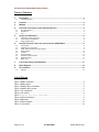
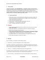
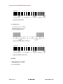
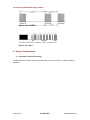
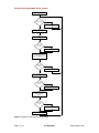
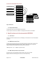
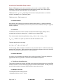
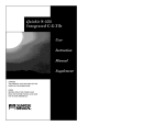
Cornelius Van Drebble Mad Design Contest
The BrainIRac
Author
Marcel Ursu
Cornelius Van Drebble Mad Design Contest
TABLE OF CONTENTS
Description ...........................................................................................................................3
1.
1.1.
Typical Applications:..........................................................................................................................................3
2.
Features ................................................................................................................................3
3.
Markets .................................................................................................................................3
4.
Overview of IR remote control data transmission ...........................................................4
4.1.
4.2.
4.3.
5.
Sony SIRC protocol...........................................................................................................................................4
Philips RC-5 ......................................................................................................................................................5
JVC...................................................................................................................................................................5
Design Considerations........................................................................................................6
5.1.
5.2.
5.3.
6.
Information capture and storage........................................................................................................................6
Further design considerations ...........................................................................................................................8
Design Implementation......................................................................................................................................9
Specific functions used in the microcontroller UPD78F9835 .........................................9
6.1.
6.2.
6.3.
6.4.
6.5.
6.6.
6.7.
6.8.
6.9.
LCD Interface....................................................................................................................................................9
TM50 Remote Control Timer .............................................................................................................................9
TM40, TM30 operated as Carrier Generator......................................................................................................9
Serial Interface ................................................................................................................................................10
8 bit ADC.........................................................................................................................................................10
Sound Generator.............................................................................................................................................10
Key Return Signal Detection ...........................................................................................................................10
Multiplier Function ...........................................................................................................................................10
Watch Timer....................................................................................................................................................11
7.
Low Power Design Considerations .................................................................................11
8.
Block Diagram....................................................................................................................12
9.
User Interface .....................................................................................................................13
9.1.
Operation ........................................................................................................................................................13
List of Figures
Figure 1 SONY modulation.............................................................................................................. 4
Figure 2 SONY packet..................................................................................................................... 5
Figure 3 PHILIPS RC-5 modulation................................................................................................. 5
Figure 4 PHILIPS RC-5 packet........................................................................................................ 5
Figure 5 JVC modulation ................................................................................................................. 6
Figure 6 JVC packet ........................................................................................................................ 6
Figure 7 capture and store algorithm ................................................................................ 7
Figure 8 Carrier parameters ............................................................................................................ 8
Figure 9 Data Store ......................................................................................................................... 9
Figure 10 Block Diagram ............................................................................................................... 13
Figure 11 User Menu ..................................................................................................................... 14
Page 2 of 14
The BrainIRac
Author Marcel Ursu
Cornelius Van Drebble Mad Design Contest
1. Description
The device we propose - called "The BrainIRac" – is designed to capture, store and transmit
multiple infrared (IR) command sequences. It greatly simplifies and speeds-up control of various
IR devices like TV, DVD, CD, etc. The BrainIRac can be described by analogy with some
computer programs (like MS EXCEL or ORCAD schematic capture) whereby the user is able to
capture and save a sequence of keystrokes as a macro. That macro can then be run as needed.
The aim is obviously, to automate and speed up repetitive tasks.
1.1. Typical Applications:
1. Home-theatre system (TV+DVD+CD+Receiver+Set-top-box) automatic turn ON / OFF
and set to initial state (source/channel selection, amplifier volume) using the original
remote, with the push of one button only.
2. In-store Audio-Video equipment demo.
3. Home Security - occupancy simulation through Audio-Video use.
4. Parental control – TV control based on time of day.
5. Party - CD changer and amplifier volume control.
2. Features
1. Able to capture commands transmitted by virtually any consumer electronics infrared
remote control (IRRC).
2. Able to store a sequence of commands with relative time stamps as a program.
3. Able to store and manage multiple programs.
4. Able to schedule and trigger execution of any stored program. In this context, execution
of a program means transmitting the sequence of commands that make up the program.
5. A program trigger is defined as a time point or a stored IR command.
6. User interface based on LCD, LED, push buttons, IR commands and audio tones.
7. Able to detect and signal the “battery low” condition.
3. Markets
Due to its flexibility, it can address several different markets:
1. Domestic use - to extend and augment IR control usage scenarios.
For example, a “DVD ON” macro would have the TV, DVD and the amplifier all turned on and
preset, in one sequence, initiated by pushing only one button on the original remote. Similarly, a
“CD” macro would control the CD changer and the amplifier.
2. Security – i.e. occupancy simulation through audio-video equipment use.
For example, all IR commands could be captured during actual TV watching time for say, 2 hours.
Then, this macro could be saved and be run on specific days and preset time.
3. Electronics Retail – automatically exercise any IR controlled product for demo purposes.
Page 3 of 14
The BrainIRac
Author Marcel Ursu
Cornelius Van Drebble Mad Design Contest
For example, all IR commands could be captured during an actual demo for say, the XYZ TV set.
Then, this macro could be saved as “XYZ TV” macro and be run whenever a customer inquires
about this TV set.
4. Overview of IR remote control data transmission
!
!
!
All IRRCs (infrared remote controls) share the basic concept of communicating to the
home entertainment device using infrared light.
There is no standard when it comes to IR remote control for audio-video equipment. All
major vendors use proprietary protocols. Some quasi-standards do exist. These include
RC-5, RC-6, SIRC. Many manufacturers such as NEC have also established their own
standards.
At the physical level, data transmission is based on a few principles of modulation that
have been established by most systems:
o
o
o
!
!
!
Use of a carrier with frequency between 25kHz and 80kHz. Carrier duty cycle can
be anywhere from 10% to 90%. The use of a carrier provides immunity from IR
ambient noise. Fluorescent lighting is one source of such noise. Carrier
transmission is accomplished by turning the IR emitter ON and OFF.
Use of OOK (ON / OFF keying) carrier modulation. That is to say, bursts of
pulses at the carrier frequency are transmitted.
Binary information is encoded (by modulating the carrier) using one of the
following three techniques: PWM (pulse width modulation), PDM (pulse distance
modulation) or Manchester (bi-phase).
There are further variations of data formats: with and without start / stop burst, with
different numbers of bits in a command and with different bit lengths.
Almost all codes have address bits and data bits.
Above the physical level, the protocols differ in the way the address and data are
encapsulated into the packet.
To illustrate, three IR remote control protocols used by Sony, Philips and JVC are presented. This
information comes from reference (2).
4.1. Sony SIRC protocol
carrier frequency Fc = 40KHz
• carrier duty cycle = ¼ or 1/3
• bit encoding: PWM
•
Figure 1 SONY modulation
Page 4 of 14
The BrainIRac
Author Marcel Ursu
Cornelius Van Drebble Mad Design Contest
Figure 2 SONY packet
4.2. Philips RC-5
carrier frequency Fc = 36KHz
carrier duty cycle = ¼ or 1/3
• bit encoding: Manchester
•
•
Figure 3 PHILIPS RC-5 modulation
Figure 4 PHILIPS RC-5 packet
4.3. JVC
carrier frequency Fc = 38KHz
• carrier duty cycle = ¼ or 1/3
• bit encoding: PDM
•
Page 5 of 14
The BrainIRac
Author Marcel Ursu
Cornelius Van Drebble Mad Design Contest
Figure 5 JVC modulation
Figure 6 JVC packet
5. Design Considerations
5.1. Information capture and storage
The BrainIRac shall capture and store the IR packets as shown in Figure 7: Capture and Store
Algorithm.
Page 6 of 14
The BrainIRac
Author Marcel Ursu
Cornelius Van Drebble Mad Design Contest
CAPTURE & STORE MODE
N
NEW PACKET
Y
MEASURE THE TIME SINCE LAST
PACKET
STORE THE TIME SINCE LAST
PACKET
DETECT CARRIER PARAMETERS
N
PREVIOUSLY
STORED
STORE CARRIER PARAMETERS
Y
CAPTURE RAW PACKET AND
COMPARE WITH PREVIOUS RAW
PACKET
Y
PACKETS ARE
IDENTICAL
N
ENCODE & STORE THIS PACKET
AS "SAME AS PREVIOUS"
DETECT START / STOP AND BIT
ENCODING
N
PREVIOUSLY
STORED
STORE START / STOP AND BIT
ENCODING
Y
CREATE HEADER AS REFERENCE
TO: CARRIER PARAMETERS,
START / STOP AND BIT
ENCODING
N
PREVIOUSLY
STORED
STORE HEADER
Y
STORE PACKET AS HEADER +
BINARY DATA
Figure 7: Capture and Store Algorithm
Page 7 of 14
The BrainIRac
Author Marcel Ursu
Cornelius Van Drebble Mad Design Contest
Further design considerations
5.2.
Another design goal is the efficient use of storage memory. A basic form of “data compression”
needs to be implemented. To that end, the protocol header is defined as a list of four parameters
that uniquely define that protocol. These parameters are:
1. Carrier Parameters
Carrier parameters refers to the pair of values (t1, t2) that represent the carrier on / carrier off
time.
t1
t2
Figure 8 Carrier parameters
2. Start / Stop Information
It shows whether the IR packet is preceded or succeeded by carrier bursts and it records their
length.
3. Encoding Method
Specifies one of the three encoding methods: PWM, PDM, Manchester.
4. Packet-to-packet interval
Specifies the amount of time separating one packet from the next one, during a burst.
The strategy is to store the attributes for each protocol encountered only once and then reference
them as needed via protocol headers. Multiple headers are used to accommodate different
protocols.
Another useful observation is that quite often, a packet is repeated – with a certain burst
frequency - for as long as the user keeps pressing the same key on the remote. Therefore, it
makes sense to look for trains of identical packets and use run-length encoding whenever they
are detected.
These concepts are illustrated in Figure 9
Page 8 of 14
The BrainIRac
Author Marcel Ursu
Cornelius Van Drebble Mad Design Contest
PACKET-TO-PACKET3
PACKET-TO-PACKET
PACKET-TO-PACKET2
PACKET-TO-PACKET1
PWM
MANCHESTER
PDM
BIT ENCODING
...
CARRIER 1
CARRIER 2
CARRIER PARAMETERS
CARRIER N
START / STOP 1
START / STOP 2
PACKET 1
...
START / STOP N
HEADER 1
...
HEADER 2
HEADER N
PROGRAM "ABC" BEGIN
PROGRAM "ABC" END
PROGRAM "XYZ" BEGIN
PROGRAM "XYZ" END
HEADER 1
PACKET 2
DATA
TIME 1
HEADER 1
RUN-LENGTH
ENCODED
DATA
TIME
COUNT
...
START / STOP PARAMETERS
TIME N
HEADER 2
DATA
Figure 9 Data Store
5.3. Design Implementation
The BrainIRac shall use the UPD78F9835 microcontroller.
The main system clock shall run at 5MHz. The subsystem clock shall run at 32.768kHz.
6. Specific functions used in the microcontroller UPD78F9835
6.1. LCD Interface
Configured as 80x16 and used to drive an LCD display of 16 characters x 2 rows. Each character
is 8x5 dots.
6.2. TM50 Remote Control Timer
The 8-bit remote control timer 50 has a pulse width measurement function with a resolution of 8
bits. It has rising / falling edge detection circuitry. Carrier t1 and t2 time count is captured in
registers CP50 and CP51 respectively, with minimal CPU intervention.
TM50 input clock = ½*fclk = 2.5MHz, or a period of 0.4µs
6.3. TM40, TM30 operated as Carrier Generator
An arbitrary carrier clock generated by TM40 is output in the cycle set in TM30.
Registers CRH40 and CR40 program carrier time t1 and t2 respectively.
Page 9 of 14
The BrainIRac
Author Marcel Ursu
Cornelius Van Drebble Mad Design Contest
Register CR30 programs the carrier modulation cycle. In order to achieve PWM or PDM
modulation, CR30 needs to be dynamically reloaded with the proper values. Servicing the
interrupt generated by TM30 (INTTM30), can accomplish this.
TM40 input clock = fclk or ¼* fclk depending on the values of carrier parameters t1, t2 and the
maximum acceptable error of generating them.
TM30 input clock = TM40 output clock
6.4. Serial Interface
Used primarily to program the microcontroller internal flash memory. An external multiplexer
allows connection of a serial RTC (real time clock) and a 3 wire serial flash memory for program
memory expansion.
6.5. 8 bit ADC
The 8-bit A/D converter is used to monitor the Vdd microcontroller supply voltage. Vdd is
compared with a reference voltage (Vref = 2.048V) input on channel ANI0.
From microcontroller electrical specifications, Vddmin = 3.0V <= Vdd <= Vddmax = 3.6V
8
VANI0 = Vref = 2.048V = N * (Vdd / 2 ); where N is the ADC conversion result
Therefore N should be in the range:
8
8
(Vref / Vddmax )* 2 <= N <= (Vref / Vddmin )* 2
To save energy, ADC conversion is started once every 5s when Vdd is in a 300mV middle range
between Vddmin and Vddmax. ADC conversion rate is increased as Vdd gets closer to the extremes.
An alarm is raised when N goes within 5% of the valid range.
6.6. Sound Generator
It is used to convey a battery low warning and to confirm key pressing. The sound generator is
programmable and can generate 16 volume levels and different frequencies.
6.7. Key Return Signal Detection
This function generates an interrupt (INTKR00) upon detecting a falling edge on any of the KR00
to KR07 port lines. Four user interface keys are connected on KR00 to KR03. The ISR (interrupt
service routine) reads the input port KR00 to KR03 to detect the active key.
6.8. Multiplier Function
The multiplier has the following function.
• Calculation of 8 bits × 8 bits = 16 bits
Page 10 of 14
The BrainIRac
Author Marcel Ursu
Cornelius Van Drebble Mad Design Contest
This function just might be needed if it turns out that further digital filtering at carrier reception
is required. Most IR receivers are built to accommodate one or a few closely related protocols.
The implication is that the carrier frequencies are the same or very close. This in turn, allows for
BPF (band pass filtering) centered on the carrier frequency to be built into the IR analog frontend.
Because The BrainIRac must be able to accommodate a wide carrier frequency range (25kHz to
80 kHz), so it cannot use an IR frontend with built-in BPF. Depending on the characteristics and
the quality of that IR frontend, digital filtering may be required to filter out the noise.
A way around this issue may be to use multiple standard IR receiver frontend devices. Each
device would be centered on a different carrier frequency, such that together, they would cover
the whole range.
6.9. Watch Timer
This is a function that could be used. However, there are some drawbacks, as will be shown
later.
It works with 32.768 kHz subsystem clock to generate an interrupt request (INTWTI) at 0.5second intervals, thus maintaining an RTC (real time clock). The ISR (interrupt service routine)
updates the RTC registers in RAM; it also checks for a match between current time and any of the
time alarms programmed to trigger execution of a particular program.
7. Low Power Design Considerations
When battery life is a concern, as is the case here, designing for lowest power is a major goal. A
decision regarding the RTC (real time clock) implementation can have a major impact on power
consumption.
The obvious thing would be to use the internal Watch Timer. However, as the datasheet quickly
reveals, uPD78F935 (flash) still draws 12mA in STOP mode, with XT (subsystem clock) = RUN.
In sharp contrast, the uPD78935 (mask ROM) only draws 40uA in the same state. The only way
to bring uPD78F935 (flash) current draw at 10uA is to enter STOP mode with XT (subsystem
clock) = STOP. Unfortunately, turning off the XT clock disables the Watch Timer and with it, the
RTC. This is the reason why this design shall use an external serial RTC featuring its own backup
power and alarm interrupt output. An added benefit is that the time count will not be lost when the
main batteries run out and need to be replaced. The processor will exit this ultra low power mode
with an external interrupt, such as RTC alarm or any user key.
Another solution to this design issue is to use the mask ROM version of this microcontroller. This
would allow using the internal Watch Timer without the penalty of high current draw and thus
remove the need for an external RTC. It is a lower cost solution but less flexible, more suitable for
high-volume production runs.
Page 11 of 14
The BrainIRac
Author Marcel Ursu
Cornelius Van Drebble Mad Design Contest
8. Block Diagram
VDD
UPD78F9835
IR
RECEIVER
RIN
TM50
VDD
REMOTE CONTROL
TIMER
ANALOG
FRONTEND
TO40
IR
TRANSMIT
TM40 TM30
CARRIER
GENERATION
BUFFER
VDD
VREF
P60
2.048V
ADC
VPP
VDD
/RESET
FLASH
PROGRAMMING
INTERFACE
MULTIPLEXER
SCK10
SI10
SO10
CLK_A
IN_A
OUT_A
CLK_B
IN_B
OUT_B
RTC
P30
SELECT
REAL TIME CLOCK
SERIAL
INTERFACE
ALARM
P04
SOUND
GENERATOR
P34
AMPLIFIER,
BUZZER
INTP1
VLC0
VLC1
VLC2
KR00
KR01
KR02
KR03
S0
S1
S2
S3
VLC3
LCD
BOOSTER
VLC4
CAP0
CAP1
CAP2
CAP3
RED
P05
GREEN
P06
COM[0:15]
LCD
16 CHARS X 2 ROWS
S[0:79]
LCD
INTERFACE
VDD
RESET
GENERATOR
Page 12 of 14
/RESET
The BrainIRac
Author Marcel Ursu
Cornelius Van Drebble Mad Design Contest
Figure 10 Block Diagram
9. User Interface
The user interacts with The BrainIRac through an Interface that is made up of:
One LCD panel of 16 characters x 2 rows,
• Four keys:
•
1. SELECT •
2. BACK •
3. UP •
4. DOWN •
Buzzer
• Bicolor LED
•
9.1. Operation
User interaction with the device is based on a hierarchical menu.
Menu items adjacent to a contiguous vertical line can be navigated to and from with the UP /
DOWN keys. The SELECT and BACK keys work similarly on the horizontal direction. Depending
on the menu context, the SELECT key can also “select” a certain action or item.
Most menu items are self-explanatory. Some require a few comments though.
SET IR CONTROL allows the user to capture and associate a particular IR command with any
program that was already stored. This feature makes it possible to use any IRRC (IR remote
control) and with just the push of a button, trigger the execution of any stored program, as
explained at the beginning of this paper.
Design note:
The IR receive and IR transmit diodes must be physically on the opposite sides of the box.
The Bicolor LED is meant to indicate remotely the mode The BrainIRac is in, using a combination
of blink rates and colors.
Page 13 of 14
The BrainIRac
Author Marcel Ursu
Cornelius Van Drebble Mad Design Contest
STANDBY
OFF
CAPTURE
START
STOP
PLAY
SET IR CONTROL
SET TIME
DEFAULT NAME
DISCARD
USER NAME
LIST
SET PLAY TIME
RENAME
LIST
ENTER NAME
DELETE
LIST
CONFIRM
IR COMMAND
SELECT
PROGRAM
LIST
SET Y,M,D,H,S
SAVE
DEFAULT, NOW
SELECT
PROGRAM
PROGRAMS
SAVE
SET DEFAULT
Figure 11 User Menu
10. References
1. Preliminary User’s Manual
µPD789835 Subseries
8-Bit Single-Chip Microcontrollers
Document No. U15559EJ1V1UDU1 (1st edition / revised in U.S.)
Date Published June 2002 N CP(K)
2. SB-PROJECTS
http://www.xs4all.nl/~sbp/knowledge/ir/ir.htm
3. Vishay Semiconductors
Data Formats for IR Remote Control
Page 14 of 14
The BrainIRac
Author Marcel Ursu