1
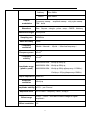
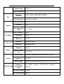
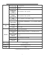
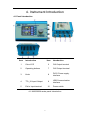
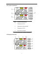
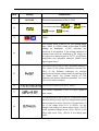
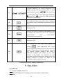
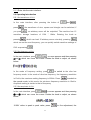
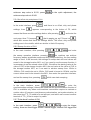
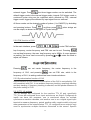
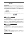
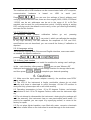
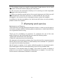
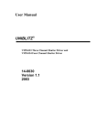
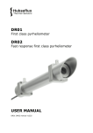
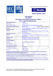
OPERATING MANUAL
MHS2300 Series
Dual-channel
DDS Signal Generator
December 2013
Zhengzhou Ming He Electronic Technology Co., Ltd.
Contents
1.Contact..........................................................................................................1
2.Inspecting Package Contens.........................................................................1
3. Summary......................................................................................................2
3.1 Brief Introduction..................................................................................2
3.2 The Instrument model ..........................................................................2
3.3 Features...............................................................................................2
3.4 Technical Data......................................................................................3
4. Instrument Introduction.................................................................................7
4.1 Panel Introduction ................................................................................7
4.2 Function Introduction............................................................................7
4.3 Display Introduction..............................................................................8
5. Operation ...................................................................................................10
5.1 Power on............................................................................................10
5.2 Operating Instruction............................................. 错误!未定义书签。
6.Caution......................................................................... 错误!未定义书签。5
7.Warranty......................................................................................................16
1. Contact
Mr. LIAO YAOFENG, Cell:008613570580543,Tel: +862034553996,
1/F, NO.2-2, SANZHUANG RD., HE CUN, DASHI TOWN,PANYU DISTRICT
, GUANGZHOU CITY, CHINA
ZIP:511430
Tel:
+862034553996,
Cell:008613570580543
2. Inspecting Package Contents
When you get a new DDS signal generator of MHS2300, please inspect the
instrument as follows:
2.1 Check if there is damage due to transportation
If the package is damaged, please retain them until the instrument and
accessories are tested.
2.2 Check package contents
Contents of the case are as bellows, if the content does not match with the
packing list or the instrument is damaged, please contact us.
DDS signal generator
1pc
Accessories:
DC 5V adapter
1pc
USB cable
1pc
Signal output cable
2pc
User manual
1pc
CD
1pc
2.3 Check the machine
If the machine was damaged; did not work properly or failed to pass
performance tests, please contact your dealer or our company.
1
3. Summary
3.1 Brief introduction
Large –scale CMOS integrated circuits, high-speed 32-bit ARM
microprocessor and surface mount technology were adopted, which improved
the instrument’s immunity and longevity greatly. 2.4 inch TFT LCD screen with
320*240 resolutions was able to display all the parameters of the two channels
and prompt the current key functions, avoid pressing buttons repeatedly. The
instrument has applications in electronic engineering labs, production facilities,
service shops, and schools.
3.2 The Instrument Model
l
MHS2300A-05M Sine frequency up to 5MHz, amplitude up to 20Vp-p
l
MHS2300A-10M Sine frequency up to 10MHz, amplitude up to 20Vp-p
l
MHS2300A-20M Sine frequency up to 20MHz, amplitude up to 20Vp-p as
frequency ≦15MHz; amplitude up to 15Vp-p as frequency >15MHz.
3.3 Features
3.3.1 Adopting direct digital synthesis (DDS) technology, FPGA design, and
ultra-low power consumption;
3.3.2 With portable aluminum alloyed shell, sole DC 5V powered adapter, easy
to carry;
3.3.3 With a 2.4-inch TFT color LCD, variable function soft keys and a rotary
encoder, greatly enhances the usability of the instrument;
3.3.4 Perfectly symmetrical two channels can be synchronized to work, and
the phase adjustable;
3.3.5 Two or multi-machines can be achieved multi-machines synchronous by
TTL_IO port;
3.3.6 Various basic function waveforms of sine, triangle, square, saw tooth,
and pulse (duty adjustable);
3.3.7 The minimum output signal frequency to 10µHz;
3.3.8 With 100 sets (M00~M99) parameter storage locations, data of M00 can
be loaded as power on;
3.3.9 With 15 sets arbitrary waveform storage locations for users self-defining,
memory depth of each set is 1024*10 bits;
3.3.10 Amplitude up to 20Vp-p as frequency ≦15MHz; amplitude up to
15Vp-p as frequency >15MHz;
3.3.11 Minimum frequency resolution reaches 10µHz, minimum amplitude
resolution to 10mV;
3.3.12 With DC offset function (-100%~+100%);
2
3.3.13 With FSK function, hop frequency, carrier frequency and FSK rate can
be set freely;
3.3.14 Three trigger modes, manual trigger, internal CH2 trigger, external
trigger, an arbitrary burst of 1~1048575 can be outputted;
3.3.15 If the setting is +100%, any CMOS digital signal of 0~10V can be
outputted;
3.3.16 Duty adjustment of pulse wave is accurate to 0.1%.
3.3.17 The burst function can control the output pulses from 1 to 1048575.
3.3.18 Frequency sweep, amplitude sweep and duty sweep with an arbitrary
start and end point.
3.3.19 With functions of frequency measurement, period measurement,
positive and negative pulse width measurement, duty cycle measurement and
counting.
3.3.20
All parameters can be calibrated by internal program.
3.3.21 Powerful communication functions and the completely open
communication protocol, which makes it very simple to the secondary
development.
3.3.22 After in connection with the PC, the PC can be used to control the
instrument and arbitrary waveforms edited on the PC can be download to the
instrument to output.
3.4 Technical data
Technical data
MHS2300A-05M/10M/20M
Normal: MHS2300A-05M:0Hz~5MHz;
MHS2300A-10M:0Hz~10MHz;
Main output
Frequency range
Sine
MHS2300A-20M:0Hz~20MHz。
Ultra-low frequency :0~600Hz
Square
0Hz~5MHz
Triangle
0Hz~5MHz
Saw tooth
0Hz~5MHz
3
Output
Arbitrary
0Hz~5MHz
CMOS
0Hz~5MHz
modulation
Frequency sweep、 amplitude sweep、duty cycle sweep、
FSK、burst
Waveform
Sine、Square、triangle、pulse、ramp、CMOS、Arbitrary
Waveform length
1024 points
Sampling rate
200MSa/s
Wave accuracy
10bits
Frequency
resolution
10mHz(Normal),10μHz( Ultra-low frequency )
Frequency error
±5×10⁻⁶
Frequency
stability
±1×10⁻⁶
MHS2300A-05M : 10mVp-p~20Vp-p;
Amplitude range
(peak to peak)
MHS2300A-10M : 10mVp-p~20Vp-p;
MHS2300A-20M : 10mVp-p~20Vp-p(frequency≦15MHz),
10mVp-p~15Vp-p(frequency>15MHz)
Output impedance 50Ω±10%
Amplitude
resolution
10mVp-p
Amplitude stability ±0.5%(per 5 hours)
Amplitude error
Offset range
Offset resolution
± 1%+10mV(frequency 1KHz., 20Vp-p)
-100%~+100%(the ratio of offset voltage to signal
amplitude)
1%
4
Phase range
Phase resolution
Sine
Square
TTL/CMOS
Harmonic
distortion
0~360°
1°
40dBc(<1MHz) ,35dBc(1MHz~20MHz)
Distortion factor
<0.8%(20Hz~20KHz)
Rise or fall time
≤20ns
Overshoot
≤10%
Duty adjustment
range
0.1%~99.9%
Rise or fall time
≤20ns
Low level
<0.3V
High level
1V~10V
Duty>50%
Rising saw tooth
Duty<50%
Falling saw tooth
Saw tooth
Quantity
Arbitrary
Memory depth /
set
Sweep mode
Sweep
Measurement
Sweep time
15 sets
1024*10bits
Frequency sweep, amplitude sweep, duty sweep
1S~99S
Sweep range
Depending on the settings saved in M1 of CH1 and CH2
Frequency
measurement
range
1Hz~60MHz(Normal),0.01Hz~1kHz( Ultra-low
frequency )
Min. input voltage 0.5Vp-p
Max. input voltage 20Vp-p
5
Counting range
0~4294967295
Counting mode
Manual
Positive and
negative pulse
width
measurement
10ns resolution,Max. up to10s
Period
measurement
20ns resolution,Max. up to20s
Duty
measurement
0.1%
Signal option
1.Ext.IN input(Analog signal ),2.TTL_IN input(Digital
signal)
resolution,0.1%~99.9%
Quantity
100
Location
M00 to M99
range
Save
Interface
Interface mode
USB to Serial Interface
Communication
speed
9600bps,19200bps,57600bps or 115200bps optional
Communication
address
01~99
Verifying mode
LRC verifying or not verifying
Communication
protocol
Open
Power supply
DC 5V adapter
Dimensions
146×96×56mm (W*H*D)
Weight
416g
3-1 MHS2300A series technical data
6
4. Instrument Introduction
4.1 Panel Introduction
Item
Introduction
Item
Introduction
1
Color LCD
6
CHI Output terminal
2
Operating buttons
7
CH2 Output terminal
3
Knob
8
DV5V Power supply
interface
4
TTL_IO Input/ Output
9
USB Communication
interface
5
Ext.In Input terminal
10
Power switch
4-1 MHS2300A series panel Introduction
7
4.2 Function Introduction
Item
Function Introduction
1
Parameters of CH1
2
Operating function prompts
3
Parameters of CH2
4
Key function prompts
4-2 MHS2300A series Function Introduction
4.3 Display Introduction
8
Item
Display
1
CH1/CH2
Introduction
The current parameters of CH1 / CH2
The current waveform,
Sine
Square
2
Triangle
3
/
Arbitrary
Off/On
4
The current offset is set to 0%, the setting range
from -100% to +100% refers to the ratio of offset
voltage to amplitude, +100% indicates the
waveform in the positive, if the setting waveform is
a square wave with an amplitude of 5V, which can
be output as a digital signal of 5VTTL, so different
amplitudes can generate different CMOS level
digital signal wave.
5
The current duty is set to 180º, the phase setting of
CH1 refers to the phase difference between two
CH1s of the different machines as multiple
machines connected, single machine working does
not make sense, the phase setting of CH2
indicates the phase difference between CH1 and
CH2 of the same machine.
6
The current frequency is set to 10kHz.
7
The current amplitude is set to 10kHz (peak to
peak value).
8
The current duty is set to 50.0%, it should be noted
that this setting is only valid for triangle and square
wave except sine wave, the duty of square wave is
set in the range from 0.1% to 99.9%, for the
triangle, the setting is in three cases: Duty = 50.0%
is the standard triangle wave, Duty> 50.0% is the
rising saw tooth, Duty <50.0% is the falling saw
tooth.
9
Generally speaking, the content displayed in the
middle indicates the key operating tips, or some
9
special setting values.
The three keys
can control channels of CH1 and CH2, specifically,
controls CH1,
controls CH2, OK controls two
channels simultaneously.
10
The model and current firmware version number of
the machine can be displayed as pressing the key
of F1.
11
Settings of CH1
12
Refers to an auxiliary function of the machine, such
as setting the sound of on or off, frequency
measurement,
cycle
measurement,
communication settings etc.
13
Settings of CH2
Two options of save and load appear by
14
pressing
, save represents the current
specific parameter settings of CH1 and CH2 to be
saved in Flash memory to the machine, there are
100 specific storage locations from M00 to
M99.Load indicates the content of the Flash
memory to be loaded, the machine can load
parameter of M00 automatically at boot time, M01
storage location is mainly for some of the
parameters set the sweep function.
4-2 MHS2300A series Display Introduction
5. Operation
5.1 Power On
5.1.1 Plug 5V adapter, switch on.
5.1.2 The LCD displays the company name and version number of the
instrument.
10
5.1.3 Enter into the main interface.
5.2 Operating Introduction
5.2.1 Set waveforms of CH1.
In the main interface, after pressing the button of
press
you press
and
,
, the waveforms of sine, square and triangle can be switched, if
, an arbitrary wave will be outputted. The machine has 15
waveform storage locations of 1024 * 10bits. Rotating the knob or
pressing
which can load 15 arbitrary waves circularly, pressing
which can set the next frequency, you can quickly switch waveform settings of
CH2 as pressing
.
5.2.2 Set frequency of CH1.
In the main interface, press
, a cursor appears and then pressing
and , which can move the cursor. Rotate the knob to adjust, as shown
below.
In the mode of frequency setting, press
to switch to the ultra low
frequency mode. In the mode of ultra low frequency, the frequency resolution
is 10uHz, the maximum setting frequency is 600Hz. Press
to switch to
the normal mode, in this mode, the minimum frequency resolution is 10mHz.
Amplitude setting is similar to that of frequency
5.2.3 Set amplitude of CH1.
In the main interface, press
, a cursor appears and then pressing
and , which can move the cursor. Rotate the knob to adjust, as shown
below.
10.00V refers to peak to peak value; press
11
to fine adjustment, the
minimum step value is 0.01V, press
to the quick adjustment, the
minimum step value is 0.04V.
5.2.4 Set offset duty and phase of CH1.
In the main interface, press
settings, then
, and there is no offset, duty and phase
appears corresponding to the button of F5, which
means that there are other settings below, after pressing
next page, then F1 becomes
and enter the
, that is paging up, as F5 turns into
,
which also means that there are settings below. The offset, duty and phase
settings are in the middle, which are similar to that of frequency.
5.2.5 Sweep function of CH1
and enter
In the main interface, after pressing
the sweep operation interface, pressing
the machine can achieve
frequency sweep, amplitude sweep and duty sweep switching,the time setting
range is from1 to 99 seconds, the settings of sweep start and end values are
saved in the storage location M01, so if you need to use the sweep function, it
is necessary to set the stored value of M01. We define the starting value is the
value of CH1 in the storage location M01, the end value is the value of CH2 in
the storage location M01, so if we want to achieve sweep from 10kHz to
100kHz, CH1 need to be set to 10kHz, CH2 need to be set to 100kHz, and the
current value need to be stored in the M01, then enter the operation interface,
which can start sweeping
and set the sweep time, pressing
5.2.6 Synchronization function of CH1
In the main interface, press
to enter the
synchronization settings, it should be noted that the synchronization function of
CH1 is available only when multi-machine connections require to maintain a
certain value of frequency and phase synchronization, set synchronization, at
the same time TTL_IO need to be set as input, and which can connect another
terminal of TTL_IO set to output by cable
5.2.7 Pulse burst function of CH1
In the main interface, press
to enter the trigger
setting, there are three trigger modes: manual trigger, internal CH2 trigger and
12
external trigger. Press
, the three trigger modes can be switched. The
default trigger mode is the manual trigger mode; internal CH2 trigger mode: a
continuous pulse sting can be outputted which affected by CH2, external
trigger mode: trigger pulse affected by input signal from an external.
All three modes set the desired number of pulses (1 to 1048575) by knobbing
, and then press
and pressing buttons. Press
can be output, as shown in the figure of 5 pulse strings:
, pulse strings set
5.2.8 FSK function of CH2
to enter FSK interface,
In the main interface, press
hop frequency, carrier frequency and FSK rate can be set. Pressing
can set hop frequency, the max. hop frequency up to 90KHz. A curse appears
as setting, the curse can be moved by pressing
and , rotate the knob to
adjust, as follows:
Pressing
can set carrier frequency, the carrier frequency is the
can set FSK rate, which is the
frequency of CH2, and pressing
frequency of CH1, its setting method has been introduced above.
5.2.9 Synchronization function of CH2
Synchronization of CH2 refers to some values of the CH2 is controlled by CH1
and consistent with CH1, it can achieve frequency tracking, amplitude tracking
and duty tracking, if frequency tracking is selected, and the phase difference is
the phase setting of CH2.
5.2.10 TTL_IO settings
TTL_IO settings are configured for the machine TTL_IO port, specifically
TTL_IO can be configured as an input and also as an output. Configured as
inputs can have two purposes, one is mentioned above for multiple
synchronous machine cascade, and another use is as a digital signal input
terminal to measure frequency, period, positive width, negative width, duty and
other parameters of the external pulse. TTL_IO configured as an output is only
used to synchronize multiple machines connected to the source. Specific
13
,you can enter the relevant settings.
operation is pressing
5.2.11 Input Settings
Input setting is used to set the input source of external measurement functions,
the input source has two options: TTL_IN (TTL_IO need to be set as input) and
Ext.IN, the essential difference between the two input sources is that TTL_IN is
for digital signal, the signal into the machine without DC-blocking capacitors,
so very low frequency signal (even less than 1Hz) can be measured, but Ext.IN
is the signal input with conventional DC-blocking capacitors, which is suitable
for most measurement applications. Specific settings are also very simple,
press
you can enter the relevant settings.
5.2.12 Sound Settings
The machine comes with a buzzer when pressing buttons and rotating knob,
you can produce sound, if you do not want to have voice prompts, you can turn
off the sound function, after pressing
, you can enter the relevant
settings.
5.2.13 Function of frequency measurements
to enter the external signal frequency measurement,
Press
you can measure the signal frequency connected to Ext.IN or TTL_IN
(specifications are determined by the input setting of section 9) signals. There
are two options for measuring the frequency, HF and LF, respectively high
frequency and low frequency, if selected in the HF, the measurement
resolution is 1Hz, the highest measurement is up to 60MHz, if selected in the
LF, the measurement resolution is 0.01Hz, the highest measurement reaches
1kHz.
5.2.14 Function of period parameter measurement
Press
, there are four measurement items can be selected,
T represents the conventional period measurement, TH indicates a positive
pulse width measurement, TL indicates a negative pulse width measurement,
these three units are ns, Duty is duty cycle measurements, actually that is the
ratio of T and TH.
5.2.15 Counting function
Press
, you can record the number of external pulse and
run operations of stop and clearing, these operations are manual, this counter
counts the maximum up to 4294967295.
5.2.16 Communication settings
14
The machine with a USB interface can be communicated with a PC computer,
communication hardware is based on USB to serial port.
Press
, you can see the settings of baud, address and
verifying, baud is the baud rate, there are four ranges (9600, 19200, 57600and
115200) can be set, addresses can be set in the range of 01 to 99.This
machine can be used for multi-connection control, Verifying setting is setting
LRC verifying mode, the default is not to verify, w hen you need high reliability,
and can run this function
5.2.17 Calibration function
All products have passed
calibration
before
go
out,
pressing
can enter it, which can calibrate the machine
to very high accuracy, but also calibrate the amplitude of CH1 and CH2,
specifications are not described, you can consult the factory if calibration is
required.
5.2.18 Language setting
The machine supports both Chinese and English interface, users can switch
as needed, the specific method is
.
pressing
5.2.19 Save / load function
There are 100 storage locations inside the machine for saving user's settings,
in the main interface, after pressing
, you can see “Memory 00”
displayed and rotate the knob, which storage location for storage can be set,
and then press
or
to complete your desired operating.
6. Cautions
6.1 Make sure the input power adapter correctly, the machine uses DC5V
power adapter;
6.2 The LCD of the instrument is fragile, perishable, please do not clash
violently and close to chemicals to avoid corrosion. As the LCD surface is
dusty and dirty, please wipe with a soft cloth carefully
6.3 Operating temperature is from -10 to 50 degrees Celsius, and storage
temperature is from -20 to 70 degrees Celsius; make sure the instrument kept
dry
6.4 Do not attempt to disassemble the instrument, destroying the package will
void the warranty, this instrument has no user-serviceable parts inside, if it
need to be repaired, you can repair it by specifying outlets, or return to the
factory for repair
6.5 Do not place lighted candles, cups filled with water, corrosive chemicals
and other unsafe items on the instrument to avoid damage to the instrument
15
6.6 The display screen is an easily contaminated, fragile device, do not touch
and crash, and avoid children playing the instrument
6.7 Do not move the instrument violently as it is working to avoid irreparable
damage to the internal circuitry
6.8 When you start the sound options, the normal ringing sound of the keys will
be accompanied, if this does not occur, in other words, the key may be
damaged or the internal circuit is damaged, please contact the supplier.
In addition to the above problems, the instrument still does not work properly,
please contact the supplier!
7. Warranty and service
Maintenance and Warranty
This instrument is a high-precision electronic device, in order to give full play to
its function, please read the following about maintenance, safety and effective
use of guidance before using.
Thank you for purchasing our products. To maximize the use of the new
product features, we recommend that you take the following steps:
1 Read safe and efficient use instruction.
2 Read the warranty terms and conditions.
We warrants to the original purchaser that its product and the component parts
thereof will be free from defects in workmanship and materials for a period of
one year from the data of purchase.
We will repair or replace, at its’ option, defective product or component parts.
Returned product must be accompanied by proof of the purchase date.
Exclusions: This warranty does not apply in the event of misuse or abuse of
product or as a result of unauthorized alternations or reapers. It is void if the
serial number is alternated, defaced or removed.
16