1
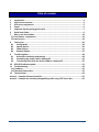
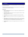
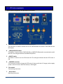
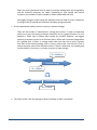
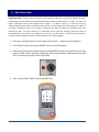
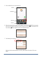
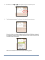
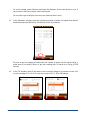
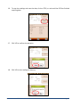
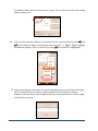
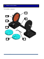
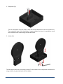
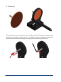
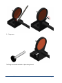
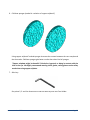
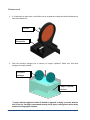
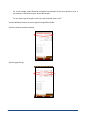
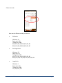
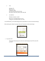
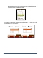
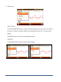
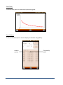
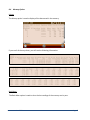
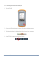
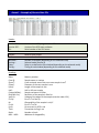
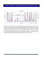
SAMPLE CORE I.P. TESTER TDLV Instruction Manual 860 boul. de la Chaudière, suite 200 Québec (Qc), Canada, G1X 4B7 Tel.: +1 (418) 877-4249 Fax: +1 (418) 877-4054 E-Mail: [email protected] Web site: www.gdd.ca Table of contents 1 Introduction ................................................................................................................ 3 2 SCIP tester accessories ................................................................................................ 4 3 SCIP tester components .............................................................................................. 5 4 Power ......................................................................................................................... 6 5 Important tips for getting good results ........................................................................ 7 6 Quick Start Guide ........................................................................................................ 9 7 How to use Core Holders ........................................................................................... 18 7.1 Core Holders - components ........................................................................................ 18 7.2 How to use it.............................................................................................................. 24 8 Tools menu ............................................................................................................... 29 8.1 Config Option ....................................................................................................... 30 8.2 Special options ..................................................................................................... 36 8.3 Show Options ....................................................................................................... 41 8.4 Memory Option .................................................................................................... 45 9 Transferring data ...................................................................................................... 48 9.1 ActiveSync installation and settings ...................................................................... 48 9.2 Connecting the Archer2 with a desktop PC ............................................................ 49 9.3 Transferring file(s) from the Archer2 PDA to a desktop PC ..................................... 50 10 GDD SCIP software update ........................................................................................ 52 11 Troubleshooting ........................................................................................................ 56 11.1 Problems.................................................................................................................. 56 11.2 Bluetooth Partnership .............................................................................................. 59 12 Technical help ........................................................................................................... 64 Annex 1 – Example of Generic Data File ............................................................................. 65 Annex 2 – Example of a resistivity/chargeability profile using SCIP Tester data .................. 66 Instrumentation GDD inc. Page 2 1 Introduction The SCIP (Sample Core I.P.) tester is a new compact, lightweight, low consumption unit designed for resistivity measurements. The SCIP tester uses a field handheld computer to process data acquisition. The operating system is Windows Embedded Handheld 6.5 Professional. Characteristics: Related to the GDD Rx 8-32: The SCIP acts as a 1 dipole receiver relating DDH Cores to the resistivity and IP surveys. Programmable windows: The SCIP offers twenty fully programmable windows for higher flexibility in defining the IP decay curve. Available Modes: Arithmetic, logarithmic, semi-logarithmic, Cole-Cole and user defined. IP display: Chargeability values, Resistivity and IP decay curves are displayed in real time on a PDA. Internal memory: Over 100 000 readings can be stored in the PDA's internal memory. Each reading includes the full set of measurement parameters. Data are stored on flash type memory and cannot be lost even if the PDAs battery is totally discharged or absent. Transmitting mode : Can be used as a low voltage transmitter of 3, 6, 9 or 12V or 0.5, 5, 50 or 500uA. Instrumentation GDD inc. Page 3 2 SCIP tester accessories A B C 1x 1x 1x D E F G H I J K L M 1x 1x 1x 1x 1x 1x 1x 1x 1x 1x N 1x SCIP tester model TDLV Set of core holders Archer2 Field computer with one rechargeable 10600mAh Li-Ion battery, one hand strap and one capacitive stylus Set of red/black cables banana/banana or banana/alligator SCIP tester AC charger with international plug kit (universal voltage) Archer2 AC charger with international plug kit (universal voltage) Serial communication cable 9 pos. D-SUB female - 9 pos. D-SUB female Archer2 micro USB sync cable Screwdriver (for Archer2 battery cap) Allen key Handy pocket tape (10’/3m) 70g bottle of Cupric Sulphate with MSDS SCIP tester Instruction Manual and SCIP tester Utilities CD (contains SCIP Tester software, Sync softwares, SCIP Tester manuals, Archer2 manual) Archer2 Quick Start Guide L 3 I A N J C K M H B Instrumentation GDD inc. E F G D Page 4 3 SCIP tester components The SCIP tester components are described in this section. A B C E D F A - RS-232 connector - 9 pin serial communication port This connector is used to connect the RS-232 cable between the Archer2 Field PDA and the SCIP tester. B - CABLE/WIRELESS switch This switch is used to select CABLE (RS-232) or WIRELESS (Bluetooth) communications with the PDA. The red light indicates the WIRELESS position. C - ON/OFF switch This switch is used to turn the SCIP tester ON. The red light indicates that the SCIP tester is ON. D - CHARGER connector This connector is used to charge the SCIP tester's battery with the AC charger, and to supply power to the SCIP tester when the battery is discharged. E - TX terminals Transmitting connectors. F - RX terminals Receiving connectors. Instrumentation GDD inc. Page 5 4 Power GDD’s SCIP tester is powered by a rechargeable Li-Ion battery. Here are a few tips for using and storing the SCIP tester. Usage Use the power supply provided by GDD to charge the SCIP tester battery. If you want to use another AC charger, make sure that the specifications are the same as those of the AC charger provided by GDD. Do not replace the SCIP internal battery without the authorization and advice of GDD’s technicians. The total operating time of the SCIP tester depends on environmental conditions. Using the SCIP in very cold weather (-200C to –400C) decreases the operating time. At normal temperatures (20°C), the operating time is from 10 to 16 hours. The power level of the batteries and the charging status appear on the main screen of the Archer2 PDA when using the SCIP program. Use the AC charger as a power supply for working with the SCIP tester when the battery level is too low. There is a protection circuit in the SCIP tester that prevents charging the battery in cold weather (under 0°C) or in hot weather (over 45°C). The SCIP will turn itself off when the battery reaches a critical low level. Storage When storing the SCIP tester for a few days or more, make sure that the battery is fully charged. Store the SCIP tester in a cool, dry place. Instrumentation GDD inc. Page 6 5 Important tips for getting good results The SCIP (Sample Core Induced Polarization) measures geophysical properties of the ore such as apparent resistivity and chargeability. The SCIP simulates an Induced Polarization survey. The waveform is ON+, OFF, ON-, OFF. The current flows through the sample and is then switched off. While the current is flowing through the sample, a resistivity (Rho) is calculated from the ON Time Voltage. When the current is switched off, the voltage across the sample drops and a decay curve is measured. The Chargeability (M) is calculated from this DECAY. Here are a few tips about preparing and measuring your core samples: Soak your core samples in water for a few days before testing them. It is recommended to soak the samples in water in order to keep their properties as in the natural environment. The best way to take measurements would be on fresh samples. If it is not possible, two days of soaking should be sufficient. Note however that it is not necessary to leave the samples to soak. The important point is to keep the same measurement conditions for all samples. The values will not necessarily match with field data but the measured values of a sample compared to another one allow defining which ones are less resistive and/or more chargeable. You may then correlate anomalies versus results from the field. Remove the excess of water on the core sample before beginning the measuring process. Use a saturated copper sulphate solution. To take a measurement, the sample is fixed between electrodes by using sponges dipped in copper sulphate solution. Make sure that some copper sulphate crystals are not dissolved in water to get a saturated solution. Before starting the measurement, make sure that the core sample is completely dry on its surface. During the whole measuring process, make sure that the work bench, the core holders and the rod that fix together the core holders are completely dry. During the measuring process, wait until the contact resistance becomes stable before taking a reading. This may take a few minutes. Select the most appropriate settings. Instrumentation GDD inc. Page 7 Select the most appropriate stack in order to stop the reading when the chargeability and the resistivity responses are stable. Depending on your sample and contact resistance, the number of stacks needed to obtain stable values will vary. We suggest using the same timing and windows than your field IP survey. Otherwise, a timing of two (2) seconds and arithmetic windows give good results. Use the appropriate mode (constant current or constant voltage). There are two modes of measurement, voltage and current. In order to determine which one to use, the contact resistance value (Rs) can be a good indication. For a Rs between 1 kOhm and 24 kOhms both modes are possible. However, we suggest selecting a constant current for an Rs lower than 1 kOhm and a constant voltage when Rs is greater than 1 kOhm. In voltage mode make sure that the Vp (mV) is greater than half of the selected voltage and in current mode make sure that the I (uA) is almost the same value of the selected current. If there is saturation, the reading may not be reliable. In that case, try a lower current or a lower voltage. Rs = 24 kOhms Constant current Constant voltage Rs = 1 kOhm Constant current Constant voltage Rs = 1 kOhm For better results, take the average of several readings on each core sample. Instrumentation GDD inc. Page 8 6 Quick Start Guide Important note : Using a finger may still be the preferred option for projected capacitive screen technology, but we understand a stylus may also be necessary (like when it’s cold). The way you hold a capacitive stylus really impacts how it works. To register a point, it is like the screen is taking a sample from which to calculate the position. It then snaps to the closest line on a grid. If you hold a capacitive stylus at an angle, it registers less area and does not calculate your true position as well. For best results on a capacitive screen like the Archer2, hold the stylus as perpendicular to the screen or straight up as you can. In this section, you will see some tips to use the Archer2 keypad to perform some actions of the SCIP program. 1. Place the core sample into the core holders (see Section 7 – How to use Core Holders). 2. Turn the SCIP tester ON using the ON/OFF switch on the front panel. 3. Select the communication mode using the CABLE/WIRELESS switch on the SCIP tester's front panel. If Cable mode is selected, connect the serial communication cable between the SCIP (RS-232 connector) and the Archer2 Field PDA. 4. Turn on the Archer2 Field PC with the ON/OFF key. Instrumentation GDD inc. Page 9 5. Click on GDD SCIP icon in the favorites bar. Title bar Dashboard Favorites Tile Bar 6. Select the communication mode: RS-232 (CABLE) or BLUETOOTH (WIRELESS). You can move back and forth between the different actions using the tab button ( ) of the keypad. Press Enter button ( ) of the keypad to perform the highlighted action. 7. The following screen appears. Make sure that the opened window is the SCIP_CORE window. See section 8.2 for more details. Instrumentation GDD inc. Page 10 8. Click START (or press 9. , and on the keypad) to begin the acquisition process. The following screen appears. The ‘Contact’ is the value of the core resistance. If the value of the core resistance is higher than 50 000 kOhms (50 MOhms), the value of the chargeability could be affected. If this should be the case, if you click on NEXT, the following message should appear: Click on Yes to continue or click on NO to stop the measuring process. Instrumentation GDD inc. Page 11 10. Click on NEXT (or press , and on the keypad) to continue. 11. Set the parameters of the core sample in the ‘Parameters’ window. D l Project name Sample length (l) mm Core sample diameter (D) mm Sample name or number Value of D in mm or S in mm2 Half sample : Cross-sectional area (S) mm2 Open the soft keyboard at the bottom of the screen by clicking on it. You can also use the numeric keypad of the Archer2 Field PC to enter numeric values. Use the tab button ( ) to advance the cursor to the next tab stop. Instrumentation GDD inc. Page 12 For a core sample, select Diameter and enter the diameter of the cross section in mm. If you measure a half core sample, select Half Sample. For any other type of sample, enter the cross-sectional area in mm2. 12. In the ‘Windows’ window, select the maximum number of stacks, the signal time and the mode (windows time definition). See Section 8.1 for more details. The time to get one reading increases with the number of stacks and the signal timing. It could take up to three(3) hours to get one reading with 50 stacks at a timing of 128 seconds. 13. In the ‘TX’ window, select if you want to use a constant voltage or a constant current. You can use a voltage of 3, 6, 9 or 12 volts or a current of 0.5, 5, 50 or 500 µAmps. Instrumentation GDD inc. Page 13 14. Click Ok (or press shift +5 OK on the keypad) to close the setting windows. 15. The following screen appears. See Annex 1 for details on the readings. In constant current mode, if a little red square appears in the window that means that the signal is saturated. Stop the measuring process, select a lower current and start the readings over. These instructions appear in a pop-up window when you click on the red square. Instrumentation GDD inc. Page 14 16. To stop the readings and save the data, click on STOP, or wait until the SCIP has finished acquiring data. 17. Click YES to confirm the operation. 18. Click YES to save readings to Memory. Instrumentation GDD inc. Page 15 The MEM: number increases by one after saving. You can save more than one reading before creating a file. 19. Click on ‘Tools’ and select ‘Memory’ to create a file with your saved data (or press , and on the keypad to open the Tools menu and press shift + or to highlight the different options) . Click on ‘Save File’ (or press when Save File is highlighted). 20. If this screen appears, select Generic to get the usual file format for SCIP tester data (.gdd file). The Geosoft button is used to create a specific file to be imported in Geosoft software. Take note that in the Geosoft file (.dat file), some information as core ID, length and diameter is missing. Instrumentation GDD inc. Page 16 21. Enter your File name and the location of your file in the Archer2 Field PC memory. 22. Click on Save to save your file. Instrumentation GDD inc. Page 17 7 How to use Core Holders 7.1 Core Holders - components 3 2 4 1 5 6 Instrumentation GDD inc. 7 Page 18 1. Receptacle (2x) The two receptacles must be used to keep the surface between the two core holders dry. The receptacles keep all the liquid (water, copper sulphate) in them. It is possible to screw the receptacles onto a table using the two base holes. 2. Holder (2x) The two holders keep the core sample in place. Fix the holders to the receptacles with two bolts using the Allen key provided with the Core Holder. Instrumentation GDD inc. Page 19 3. Electrode (2x) The electrode consists of a copper disc with a stainless steel bolt. The banana connector can be inserted into the bolt for better contact. It is possible to adjust the distance between the electrode and the holder by screwing or unscrewing the electrode using the Allen key. Instrumentation GDD inc. Page 20 4. Rod (2x) The rod fixes the two holders together. Move one of the holders along the rod to keep the core sample in place. It is possible to connect two or three rods together if the core sample is too long for one rod. To affix the rod, insert and screw. To remove the rod from the holder, unscrew the rod. If it becomes hard to unscrew the rod, use a 5/8’’ wrench or the Allen key provided with the Core Holder. Instrumentation GDD inc. Page 21 5. Fixing screw The fixing screw holds the holder in place along the rod. Instrumentation GDD inc. Page 22 6. Cellulose sponges (soaked in a solution of copper sulphate*) Using copper sulphate* soaked sponges increases the contact between the core sample and the electrodes. Cellulose sponges give better results than other kind of sponges. *Copper sulphate might be harmful if inhaled or ingested; or being in contact with the skin or the eye. We highly recommend wearing nitrile gloves, safety glasses and a safety mask when using copper sulphate. 7. Allen key See points 2, 3 and 4 to know how to use the Allen key with the Core Holder. Instrumentation GDD inc. Page 23 7.2 How to use it 1. It is important to place each core holder into its receptacle to keep the surface between the two core holders dry. Holder Receptacle 2. Soak the cellulose sponges into a solution of copper sulphate*. Make sure that both sponges are totally soaked. Cellulose sponges Copper sulphate solution * Copper sulphate might be harmful if inhaled or ingested; or being in contact with the skin or the eye. We highly recommend wearing nitrile gloves, safety glasses and a safety mask when using copper sulphate. Instrumentation GDD inc. Page 24 3. Place one, two or three graduated rods between the core holders depending on the size of the core sample. 4. Make sure that the sponges touch the electrodes. Electrode Instrumentation GDD inc. Cellulose sponge Page 25 5. Place the core sample between the sponges and affix the core holders by using the fixing screw. Core sample fixed between the sponges Fixing screw 6. On the SCIP tester, connect Tx-A with Rx-A and Tx-B with Rx-B. Tx-A / Rx-A Instrumentation GDD inc. Tx-B / Rx-B Page 26 7. Connect electrodes A and B to the Core Holders. 8. During the whole measurement process, the surface between the core holders should always be completely dry. Dry area Instrumentation GDD inc. Page 27 If you need four electrodes to be able to use your own core holders with the GDD SCIP tester, or to use the SCIP as a field IP Tester (see Section 8.2), use the two Tx connectors on the SCIP tester for transmitting and the two Rx connectors for receiving. Receiving electrodes Transmitting electrodes It is important to clean the Core_Holder after each use to prolong its lifespan. Instrumentation GDD inc. Page 28 8 Tools menu Click TOOLS to select one of the following options: Config Use the CONFIG option to change: Core sample parameters Transmitter voltage Signal timing Mode Special Use the SPECIAL option to: Re-initialize the communication between the SCIP tester and the Archer2 Field PC Use the SCIP Tester as a low voltage transmitter only Use the SCIP Tester as a field IP tester Show Use the SHOW option to display: Hotkeys (shortcut keys) Signal graph Decay curve Windows chargeability Instrumentation GDD inc. Page 29 Memory Use the MEMORY option to: See the History Recall the previous memory Clear the memory Save data in a file About Use the ABOUT option to display SCIP tester software version number. 8.1 Config Option The Parameters section is used to set the core sample parameters: D l Project name Sample length (l) mm Core sample diameter (D) mm Sample name or number Value of D in mm or S in mm2 Half sample : Cross-sectional area (S) mm2 Open the keyboard at the bottom of the screen by clicking on it. You can also use the numeric keypad of the Archer2 Field PC to enter numeric values. Use the tab key to advance the cursor to the next tab stop. Instrumentation GDD inc. Page 30 For a core sample, select Diameter and enter the diameter of the cross section in mm. If you measure a half core sample, select Half Sample. For any other type of sample, enter the cross-sectional area in mm2. Use the Windows section to set the signal timing and the mode. Set the maximum number of stacks. Set the signal timing. Instrumentation GDD inc. Page 31 Select the mode. Here are the different modes you can use: Arithmetic Windows: 20 Delay (ms): 240 Timing (ms): 2000 80, 80, 80, 80, 80, 80, 80, 80, 80, 80, 80, 80, 80, 80, 80, 80, 80, 80, 80, 80 Semi logarithmic Windows: 20 Delay (ms): 40 Timing (ms): 2000 40, 40, 40, 40, 40, 40, 80, 80, 80, 80, 80, 80, 80, 160, 160, 160, 160, 160, 160, 160 Logarithmic Windows: 4 Delay (ms): 160 Timing (ms): 2000 120, 220, 420, 820 Instrumentation GDD inc. Page 32 Cole Windows: 20 Delay (ms): 20 Timing (ms): 2000 20, 30, 30, 30, 40, 40, 50, 60, 70, 80, 90, 100, 110, 120, 130, 140, 150, 160, 180, 200 User defined Windows: between 1 and 20 Delay (ms): user defined (20ms or more) Timing (ms): user defined (20ms ore more) In the USER mode, you can load settings you have saved before, or you can create new settings. After selecting User Mode, the program asks you if you want to load saved settings. If you select YES : The program will prompt you to select the saved settings to load. Click on the file you need. Instrumentation GDD inc. Page 33 The loaded settings will be displayed in this window. If you select NO : The program will lead you to this window where you can modify the length of the windows. Instrumentation GDD inc. Page 34 After entering the windows size, click on OK button. You will be prompted to save your settings. Select ‘Yes’ to save your settings. The TX section is used to set the transmitter fixed voltage between 3, 6, 9 and 12 volts or fixed current between 0.5, 5, 50 or 500 μAmps. Instrumentation GDD inc. Page 35 8.2 Special options Reinit COM Select Reinit COM to re-initialize the communication between the SCIP tester and the Archer2 Field PC. This option is useful to reinitialize the Bluetooth link if the SCIP has been turned off and on again. Tx Control Select Tx Control if you need to use a low voltage transmitter only (without a receiver). Instrumentation GDD inc. Page 36 Select Voltage if you need a constant voltage, or Current if you need a constant current. The contact resistance appears automatically. Contact resistance Select the value of the constant voltage or the value of the constant current you need to transmit. Select the timing. Instrumentation GDD inc. Page 37 Click on the ON button to turn the transmitter on. The transmitted current appears. The little green square indicates the transmitted signal polarity. Transmitted current Signal polarity You cannot change the value of the transmitted voltage or transmitted current while the transmitter transmits. Click on the OFF button to stop the transmitter. Instrumentation GDD inc. Page 38 Click on the CLOSE button to quit the Tx Control option. SCIP Mode Select SCIP Mode and Field IP if you want to use the SCIP Tester as a Field IP Tester. The title of all windows will turn into GDD SCIP Field. Instrumentation GDD inc. Page 39 Follow steps 8 to 10 of Section 6 – Quick Start Guide to begin the measuring process. For step 11, set these parameters: Tx line number, Rx line number, line direction, transmitter position and receiver position. Enter a line number and select the line direction. A negative number cannot be entered for the line; the labels N, S, E and W are used to define the direction. Enter the transmitter and receiver electrodes position. A negative number is used to define South and West. Use the Increment setting to increment all stations evenly at the same time. Enter the number of the increment and click on the INC button to increment all stations. Tx position First electrode Second electrode Rx position First electrode Second electrode Follow steps 12 to 21 of Section 6 – Quick Start Guide to complete the measuring process. Instrumentation GDD inc. Page 40 8.3 Show Options For the Show Signal, Show Decay and Show Windows options, you have to wait until Step 15 of Section 6 – Quick Start Guide before using them. Hotkeys This feature is useful if you are using an Allegro CX or Allegro MX PDA. Show Signal The Show Signal option is used to display the signal graph of the transmitted voltage or the signal graph of the current that is passing through the core sample. Graph TOOLS menu Increase Scale Increase Offset Decrease Offset Decrease Scale Instrumentation GDD inc. Offset Scale Time Scale Graph type Selection Close graph button Page 41 1. Select offset scale. The offset is in mV for the Voltage graph and in uA for the Current graph. 2. Select time scale. 3. Select graph type Instrumentation GDD inc. Page 42 4. TOOLS menu : Auto Correction The AUTO CORRECTION option is used to optimize the graph scale and correct the offset of the signal. This option should be used after one signal period (8 secs for a 2 sec time base). Restore The RESTORE option is used to reset the default settings. PAUSE/GO The PAUSE/GO option is used to pause or play the signal. Instrumentation GDD inc. Page 43 Show Decay The Show Decay option is used to display the decay graph. Show Windows The Show Windows option is used to display the windows chargeability. Window number Instrumentation GDD inc. Chargeability value Page 44 8.4 Memory Option History The History option is used to display all the data saved in the memory. If you scroll all the way down, you will see the following information. Back Mem The Back Mem option is used to clear the last readings of the memory one by one. Instrumentation GDD inc. Page 45 Clear Mem The Clear Mem option is used to clear all the readings of the memory. Make sure that you have created a file with your saved readings before erasing the readings. Click ‘Yes’ to confirm the operation. Enter ‘9999’ in the text box and click ‘Confirm’ to clear the memory. Instrumentation GDD inc. Page 46 Save File The Save File option is used to create a file with your saved readings. The usual file created with the SCIP Tester program is the Generic file with .gdd extension (see Annex 1 for an example of the .gdd file). It is also possible to get a file compatible with Geosoft software by selecting Geosoft. The extension of this file is .dat. By selecting Geosoft, you will get both a .dat file and a .gdd file. You have to enter a File Name and a location for this file. File name File location Click on Save to create your file. You can now clear the readings of the memory (Clear Mem Option) before starting a new measurement process. Instrumentation GDD inc. Page 47 9 Transferring data If you run Vista or Windows 7 on your computer, install Windows Mobile Device Center 6.1 from the CD-ROM provided by GDD to sync content between your PDA and your computer. Or you can download it for free from Microsoft website. Use ActiveSync if you run Windows XP or earlier. 9.1 ActiveSync installation and settings 1. In order to establish communication between the Archer2 and a desktop PC, you need to install the ActiveSync software, which is available on the CD supplied by GDD. 2. Once ActiveSync is installed, a gray icon appears in the bottom right corner of your desktop PC screen. 3. Right click on the ActiveSync icon to open the following menu and select Connection Settings... 4. Check Allow USB connection with this desktop computer. Instrumentation GDD inc. Page 48 9.2 Connecting the Archer2 with a desktop PC 1. Turn the PDA ON 2. Connect the USB cable between the Archer2 PDA and your desktop computer. 3. The desktop ActiveSync (or Windows Mobile Device Center) icon is now green. 4. A small PCLink icon appears on the Archer2 title bar. Instrumentation GDD inc. Page 49 9.3 Transferring file(s) from the Archer2 PDA to a desktop PC 1. Double click on the My Computer icon on your desktop PC. 2. Double click on the Mobile Device's icon. 3. Double click on the Main folder icon. 4. Double click on the My Documents folder. Instrumentation GDD inc. Page 50 5. Use the drag and drop or cut, copy and paste functions to move file(s) between your Archer2 and your desktop PC. The data file is named: File_Name.gdd 6. Open the saved files with Notepad or Excel. Instrumentation GDD inc. Page 51 10 GDD SCIP software update 1. Connect the USB cable between the Archer2 Field PDA and your desktop computer. 2. Double click on the My Computer icon on your PC's desktop . 3. Double click on the Mobile Device icon. Instrumentation GDD inc. Page 52 4. Double click on the Main folder icon. 5. Double click on the Program Files icon. 6. The GDD SCIP program files are located in the GDD folder. Instrumentation GDD inc. Page 53 7. Rename the old version of the software to keep a backup on your Archer2 PDA. Right click on the GDD folder and select Rename. 8. Rename the folder (example: GDD_ Old_Version). 9. Right click on the Program Files window and create a new GDD folder. Instrumentation GDD inc. Page 54 10. Use the drag and drop or the copy and paste functions to move the new GDD SCIP software files from your computer to your Archer2 PDA's new GDD folder . Instrumentation GDD inc. Page 55 11 Troubleshooting 11.1 Problems This section explains some problems that could occur while using the SCIP tester as well as some proposed solutions. For any issues regarding the Archer2 Field pocket PC other than those related to the GDD program, please refer to Archer2 PDA user's manual available on the Archer2 User Documentation CD, sent by GDD. Problem : The SCIP tester does not turn on when the On-Off switch is at ‘On’. Solution : If the SCIP tester’s battery power rating is below the critical threshold, the SCIP tester will not come on line. (See the Power section for more details.) Problem : The message “Battery Error” appears on the main screen of the SCIP program on the Archer2 PDA. Solution : A problem has occured while charging the SCIP battery: over voltage, charging under 0°C or over 45°C, the charging time was too long, the battery is defective, etc. Try to disconnect and re-connect the AC charger. Instrumentation GDD inc. Page 56 Problem : The message: ‘NO SCIP’ is shown in the program bar of the SCIP program. It stays on the bar even if the SCIP tester is connected to the Archer2 PDA. Solution : Check that the SCIP tester’s On-Off switch is at On and that the LED is on. Verify that the SCIP tester’s battery is powered enough and not within the critical threshold limit. In Cable mode, verify that the cable is plugged correctly into the SCIP tester and into the Archer2 pocket PC. In Bluetooth mode, check if a Bluetooth Partnership has been established between your SCIP Tester and your Archer2 PDA (see Section 11.2 – Bluetooth Partnership). Problem: In Bluetooth mode, a COM Error message appears: Instrumentation GDD inc. Page 57 Solution : Look at the Bluetooth icon in the Dashboard: If it is gray, click on the icon to enable it. Try to start the SCIP software in Bluetooth mode again. The Cable / Wireless switch of the SCIP tester must be in the Wireless position and the SCIP tester must be ON. Check if the SCIP’s battery is sufficiently charged. The Bluetooth mode requires more power than the Cable mode. Check if a Bluetooth Partnership has been established between the Archer2 PDA and the SCIP tester (see Section 11.2 – Bluetooth Partnership). Instrumentation GDD inc. Page 58 Problem : This message appears when clicking on START to begin the measuring process: Solution : Click OK to close the pop-up window. Go to TOOLS | Config | Windows and select a timing of 0.5, 1, 2, 4 or 8 seconds. 11.2 Bluetooth Partnership To avoid wasting time searching for Bluetooth devices, a Bluetooth partnership must be established between the Archer2 PDA and the SCIP tester before connecting. This partnership was set up by GDD before the unit was sent out. However, it is possible that you might have to reconfigure it and here are the instructions: 1. Turn on the SCIP tester and place the Cable/Wireless switch in Wireless position. 2. Turn on the Archer2 Field PC. Instrumentation GDD inc. Page 59 3. Make sure the Bluetooth is on. If the icon is gray, click on the icon to enable it. 4. Click on the Bluetooth icon in the Title Bar. Instrumentation GDD inc. 5. Click on Add new device... 6. The program will search for Bluetooth Devices. This step may take a few seconds. 7. Select the SCIP’s name (SCXXXX) and click on Next. Page 60 8. Enter the passcode 1234 and click Next. Open the virtual keyboard or use the numeric keypad of the Archer2 PC. 9. This message may appear for a few seconds. Click on Advanced or wait until it disappears and click on your SCIP name. 10. Check Serial Port and click on Save. Instrumentation GDD inc. Page 61 11. Select COM Ports. 12. Click on New Outgoing Port. 13. Select your SCIP’s name and click on Next. Instrumentation GDD inc. Page 62 14. Open the port menu. 15. Select COM9 and click Finish. 16. The name of your SCIP tester should appear with the COM9 tag. Click on the Ok button to close the window. 17. The connection between the Archer2 PDA and the SCIP tester is now possible via the Bluetooth operating mode. Instrumentation GDD inc. Page 63 12 Technical help If you encounter a problem not described in this manual, do not hesitate to contact Instrumentation GDD Inc. for help at: Tel.: Fax: Toll free line: e-mail: (418) 877-4249 (418) 877-4054 1 877 977-4249 [email protected] Emergency out of business hours: Pierre Gaucher: Régis Desbiens: Home phone: Cell phone: Home phone: Cell phone: (418) 657-5870 (418) 261-5552 (418) 658-8539 (418) 570-3408 Any GDD SCIP tester that breaks down while under warranty or service will be replaced free of charge upon request for the duration of repairs, except for shipping fees. This service is subject to instrument availability but we have been able to honour this commitment up to now. Printed in Canada Instrumentation GDD inc. VER0-1.01 Page 64 Annex 1 – Example of Generic Data File Header : Version PPC : Version SCIP : SN : Version of the SCIP program on the PDA Version of the SCIP tester software Serial number of the SCIP tester Project : Name of your project Windows : Settings : Delay : Timing : Number of windows (depending on the selected mode) Selected mode (Section 8) Delay in ms before the first window (depending on the selected mode) Timing of each window (depending on the selected mode) Readings: Mem: Core ID: S(mm2): D(mm): l(mm): Half : Contact(kOhm): Rho(Ohm*m): Vp(mV): Err Vp: M: Err M: I(uA): Time: Stack: M01 – M20: Memory number Sample name or number Cross-sectional area of the none core sample in mm2 Diameter of the core sample in mm Length of the sample in mm Half or full core sample Sample resistance in kOhm Resistivity of the sample in Ohm*m Voltage at the edges of the sample (must be under 13V) Error in % of the Vp Chargeability of the sample in mV/V Error in % of M Current sent by SCIP in uA Transmitter timing in ms Number of stack Windows of chargeability Instrumentation GDD inc. Page 65 Annex 2 – Example of a resistivity/chargeability profile using SCIP Tester data We can note that when the resistivity increases the chargeability increases also. In certain conditions it is useful to calculate a normalized chargeability. This normalization is the metal factor, MF. The MF parameter is the ratio between the chargeability and the resistivity. For a high chargeability with a low resistivity the ratio increases allowing a better discrimination to define metallic mineralization (graphite). However, metallic minerals (sulfides) are often disseminated with a high chargeability corresponding to a high apparent resistivity, in which case the MF parameter is less useful. The metal factor generally used is MF = M *1000 / Rho. Instrumentation GDD inc. Page 66