1
RIDE-ST7
Raisonance Tools for the ST7 family
Overview and
Getting Started
March 2005
Introduction
RIDE-ST7
Table of Contents
1. INTRODUCTION
4
1.1
RIDE-ST7
5
1.2
Raisonance tools for the ST7 family
5
1.3
Third party tools that can be used in conjunction with RIDE-ST7
6
1.4
List of supported derivatives
6
2. CREATING A PROJECT USING THE RAISONANCE TOOLS
7
2.1
Using the example project
8
2.2
Creating a new project
8
3. CREATING A PROJECT USING THE COSMIC C TOOLCHAIN
10
3.1
About Cosmic Tools for ST7
11
3.2
Integration with RIDE
11
3.3
Configuring RIDE and the COSMIC C toolchain to work together
11
3.4
Creating a new project
11
4. CREATING A PROJECT USING THE METROWERKS C TOOLCHAIN
15
4.1
About Metrowerks Tools for ST7
16
4.2
Integration with RIDE
16
4.3
Configuring RIDE and the Metrowerks C toolchain to work together
16
4.4
Creating a new project
16
5. BUILDING AN APPLICATION WITH RBUILDER
20
5.1
About RBuilder for ST7
21
5.2
Configure a project using RBuilder
21
5.3
Configuring your project
22
5.4
Generating your project
23
5.5
Adding your application code
23
5.5.1
The main file
24
5.5.2
The interrupt file
26
5.6
Adding your code to the project
27
-2-
RIDE-ST7
Introduction
6. DEBUGGING WITH THE SIMULATOR
28
6.1
About the simulator for ST7
29
6.2
Launching the simulator
29
6.3
Using the simulator
31
6.4
Simulating a peripheral
31
6.5
Using breakpoints
32
7. DEBUGGING WITH HARDWARE TOOLS
34
7.1
Selecting hardware debugging tools
35
7.2
RLink-ST7 programming (ICP) and debugging (ICD) features
36
7.2.1
Configuring the RLink
37
7.2.1.1
RLink jumpers
39
7.2.1.2
Option Bytes
40
7.2.1.3
Instant actions
41
7.2.2
Advanced breakpoints
42
7.2.3
Hints and Troubleshooting
43
7.2.3.1
Example projects
43
7.2.3.2
Testing USB driver, connections and power supplies
43
7.2.3.3
ICCCLK and ICCDATA pins
43
7.2.3.4
Handling option bytes
43
7.2.3.5
Command-line programming tool
44
7.2.3.6
Limitations of RLink compared to the emulators
44
7.3
ST7-DVP3 and EMU3 series emulator features
46
7.3.1
Configuration
46
7.3.2
Trace Recording
46
7.4
EMU3 series emulator special features
48
8. BUILDING AN ICC-COMPLIANT APPLICATION BOARD
49
8.1
50
ICC Connector
8.1.1
ICCDATA and ICCCLK pins
50
8.1.2
RESET pin
50
8.1.3
ICCSEL/VPP pin
50
8.1.4
ICCOSC pin
51
8.1.5
VDD_APPLI pin
51
-3-
Introduction
RIDE-ST7
1. Introduction
RIDE-ST7 is an integrated development environment (IDE), designed for
the development of ST7 projects from the beginning to the end. To help
users get started building their applications from scratch with minimum
knowledge of the ST7 architecture and peripherals, RIDE-ST7 includes
RBuilder, which walks users through peripheral configuration and
generates the necessary code in a startup project. RIDE-ST7 can be
used with a range of development tools including the software-based
simulator, the RLink, and the ST7-EMU3 and ST7-DVP3 series
emulators.
This chapter gives an overview of the various tools that can be used in
conjunction with RIDE-ST7.
-4-
RIDE-ST7
Introduction
1.1 RIDE-ST7
RIDE is Raisonance Integrated Development Environment. It features: an editor/debugger/project
manager that is common to several ST microcontroller families, including ST5, ST6 and uPSD.
In its ST7 version, RIDE-ST7 is different from all other RIDE products in that it supports (or it
can drive) a larger than usual number of development tools for ST7, from Raisonance, ST and
other third party developers.
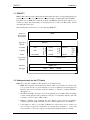
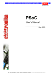
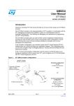
The following table shows the set of tools composing RIDE-ST7:
Integrated
Development
Environment
RIDE
AST7
Compiler
CST7
Linker
SmartLinker
Post-Linker
Optimizer
CAST7
Cosmic C
toolchain
Assembler
CXST7
CLINK
MAST7
RLST7
Raisonance
toolchain
RBuilder
Metrowerks C
toolchain
Application
Builder
CodeCompressor
Simulator
SIMICE ST7
Debugger
DVP3 - EMU3 - RLINK
1.2 Raisonance tools for the ST7 family
RIDE-ST7 comes with a number of ST7-specific tools from Raisonance:
• RIDE: this integrated development environment, which is the interface for all the other
tools, provides an editor, a project manager (no need for a makefile) and a debugging user
interface that can be used either with the simulator or with most available hardwaredebugging tools.
• Assembler and Linker: they allow you to write applications in assembler. They are similar
to their existing ST5 and ST6 counterparts. They are not compatible with the other ST7
toolchains. (e.g. ST, Cosmic or Metrowerks)
• Simulator: simulates core (including the entire memory space) and most peripherals.
Complex peripherals (USB, CAN) and some less common peripherals are not simulated.
• CodeCompressor: this is a post linker optimization tool that can be used to reduce code
size. It accepts as input any executable code, whether from assembler, C or any other
source (libraries...). It does not support code generated by the Metrowerks C toolchain.
-5-
Introduction
RIDE-ST7
• RBuilder: a graphical user interface that guides the user through the configuration of the
ST7 peripherals to be used by the application, and generates the corresponding source code
for the peripherals.
• RLink-ST7: this USB hardware dongle allows the user to program the ST7 on an
application board and debug the application while it runs on the ST7. It uses the ICC
protocol. See more information in the ICC section of this document. For more information
on using the RLink, refer to this chapter: "Debugging with Hardware Tools".
Each tool mentioned above has its dedicated user manual (please refer to it for more details) apart
from RIDE, the simulator and RLink-ST7.
1.3 Third party tools that can be used in conjunction with RIDE-ST7
RIDE-ST7 can be used together with a number of third party tools including:
• The Cosmic C toolchain (compiler, linker, assembler) has been fully integrated so that it
can be used without ever leaving RIDE. This makes it possible to use RBuilder to start
creating your ST7 application. To start using RIDE with the Cosmic C toolchain, refer to
the chapter, "Creating a project using the Cosmic C toolchain".
• The Metrowerks C toolchain versions 1 and 2 (compiler, linker, assembler) have been fully
integrated so that they can be used without ever leaving RIDE. This makes it possible to
use RBuilder to start creating your ST7 application. To start using RIDE with the
Metrowerks C toolchain, refer to the chapter, "Creating a project using the Metrowerks C
toolchain".
• ST Emulators: the RIDE debugger can drive ST emulators (EMU3 and DVP3 series
emulators), including all the emulator specific features such as trace and advanced
breakpoints. For more information on using the ST emulators, refer to the chapter,
"Debugging with Hardware Tools".
RBuilder is a 100% Raisonance product, however it uses the ST7 Library for most of the code it
generates. This implies that:
• As the ST library evolves, so will the code generated by RBuilder (starting from the same
set of options).
• As the library is written in C, using RBuilder will require the use of a C Compiler.
1.4 List of supported derivatives
RIDE-ST7 supports most of the existing ST7 derivatives to various degrees. The up-to-date list of
supported derivatives and the limitations to the software simulation can be seen in the Target
Options in RIDE.
-6-
RIDE-ST7
Creating a project using the Raisonance tools
2. Creating a project using the Raisonance tools
Assembly applications can be written using the Raisonance free
assembler. CodeCompressor can be used with this toolchain. This
chapter gives an overview of how to create an ST7 assembler project
with RIDE-ST7.
Note: Using RBuilder requires the use of a C compiler and therefore is
not possible with the Raisonance toolchain. For information about
creating projects when using a C toolchain, refer to these Chapters:
"Creating a project using the Cosmic C toolchain" or "Creating a
project using the Metrowerks C toolchain".
-7-
Creating a project using the Raisonance tools
RIDE-ST7
2.1 Using the example project
RIDE-ST7 is provided with an example project written in assembler that is ready to run. To open
this project, use "Project" -> "Open" in RIDE and select the project ASM_DEMO.PRJ. For
standard installation of RIDE, this file is found in C:\RIDE\EXAMPLES\ST7\ASM.
This example is described either in the comments in the source file and in the MAST7 manual.
2.2 Creating a new project
To create a new project in Raisonance assembler for ST7 (MAST7):
• In RIDE, choose "Project" -> "New...".
• Choose the Application name, enter the path of the application and select the ST7 target
family (this only applies if you have other versions of RIDE installed) and click on "Next".
-8-
RIDE-ST7
Creating a project using the Raisonance tools
• Select the derivative you want to work with.
• To use Raisonance tools for the project, click on "Properties", and select “Raisonance
Tools” and click on "Next".
• Click on "Finish", do not choose "RBuilder" (RBuilder would generate C code and you
need a third party compiler to be able to use it).
• Add files to the project, build and debug it as explained in the RIDE manual. (common to
all targets) To open this manual, click on "Help"->"PDF"->"Ride General"->"Ride".
-9-
Creating a project using the Cosmic C toolchain
RIDE-ST7
3. Creating a project using the Cosmic C toolchain
RIDE-ST7 integrates the Cosmic C toolchain (C Compiler, Assembler
and Linker) in such a way that it is possible to use it without ever leaving
RIDE. This environment allows the use of RBuilder and
CodeCompressor. This chapter explains how to install and use the
Cosmic C toolchain together with RIDE.
- 10 -
RIDE-ST7
Creating a project using the Cosmic C toolchain
3.1 About Cosmic Tools for ST7
The Cosmic C toolchain for ST7 is composed of a C Compiler, an Assembler and a Linker. The
ST7-specific extensions to the ANSI C language are somewhat different from those used by
Raisonance compilers, so beware if you are a user of RIDE for ST5 or ST6. Note also that
Cosmic assembler and linker are not compatible with those from Raisonance. The Cosmic C
toolchain is compatible with both RBuilder and CodeCompressor.
Important note: CodeCompressor requires a special version of the Cosmic linker. RIDE will ask
you if you want to install it.
3.2 Integration with RIDE
RIDE provides a convenient way to drive Cosmic tools via its graphical user interface. When
used in conjunction with the Cosmic C toolchain RIDE allows you to:
• Set the main compiler and other tool options graphically, via user-friendly dialog boxes.
• Automatically produce the link file (.lkf file) adapted to the chosen derivative.
• Automatically manage file dependencies so that no makefile is necessary.
• Display errors in a dialog box where a double click on the error automatically opens the
editor with the corresponding source file at the line that is the source of the error.
Please refer to Cosmic’s manuals and documentation (not included in RIDE) for details about the
Cosmic tools.
3.3 Configuring RIDE and the COSMIC C toolchain to work together
In order to use RIDE together with the Cosmic C toolchain, you need to install the two software
packages on your computer.
The Cosmic tools are not included in the distribution of RIDE-ST7. The evaluation version is
available for download at www.cosmic-software.com
Note that both RIDE and the Cosmic tools require registration to unlock some functionalities:
you need to register RIDE if you want to use CodeCompressor and you need to register the
Cosmic tools if you want them to be able to generate more than 1kb of code.
Once you have the two packages properly installed and registered, you need to tell RIDE where
the Cosmic tools are located: by default, RIDE looks for the Cosmic tools under c:\cosmic\cxst7,
which is the default directory proposed by the Cosmic installation program. If you change this
directory during the Cosmic tools installation, this must be indicated to RIDE. To do this, select
"Options" -> "Target" -> "Properties" -> “Cosmic Tools Path”.
In order to check your tools, open one of the examples for Cosmic (by default in
"C:\RIDE\examples\ST7\C\COSMIC\"). Eventually, modify the Cosmic tools path as explained
just above. Then, build the example, just to check that the tools are correctly installed and
configured to work together.
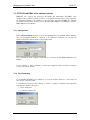
3.4 Creating a new project
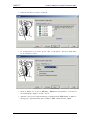
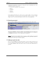
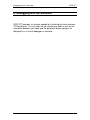
To create a new RIDE project, select "Project" -> "New...". The screen shown below will be
displayed:
- 11 -
Creating a project using the Cosmic C toolchain
RIDE-ST7
Enter your application name, the directory where you want your application to be generated, and
make sure the target family is ST7. When you are done, click on "Next".
Note that you can click on "Cancel" to cancel the creation of your project at any time when using
the wizard. The Help button may also be used to get some help on the creation of a new project.
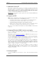
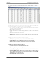
Once you have clicked on the "Next" button, you will see the following window:
In the Device tab, select the ST7 derivative that you want to use.
In the Properties tab, select the Cosmic C toolchain. You must now specify top-level choices that
impact the whole toolchain including:
• The Memory model to use.
• Whether you will use floating point libraries.
For more information about these options, refer to the Cosmic manuals.
- 12 -
RIDE-ST7
Creating a project using the Cosmic C toolchain
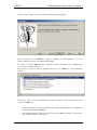
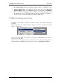
Click on "Next" when you are done and the following screen will appear:
Here, you can choose to use RBuilder to help you configure your ST7 application, or you can
click on "Finish" and create your application manually.
If you choose to use the RBuilder, refer to Chapter 5 for more information about configuring the
project and your ST7s peripherals.
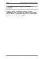
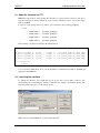
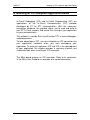
In both cases at least two files are generated (more if you use RBuilder, see the illustration
below).
The last two files (vector.c and master.lkf) are always generated. The others depend on the
options set in RBuilder.
• vector.c contains the reset vector definition (and possibly other interrupt vectors definitions
if it has been generated by RBuilder)
• <projectname>.lkf is the linker file and is generated by RIDE according to the derivative
chosen and the structure of the project.
- 13 -
Creating a project using the Cosmic C toolchain
RIDE-ST7
The gray icons for vector.c and the link file indicate that these files are not handled by the linker
as the other files are. vector.c is linked in a special place. The .lkf file is the linker script. See
Cosmic documentation for more information about it. They are present in the project for fast and
easy display of their contents. These files should only be edited to meet very precise
requirements. This requires an advanced understanding of the Cosmic toolchain.
Warning: the vector definition file and the link file are created automatically after you have
chosen your derivative. Changing derivative on an existing project might lead to the regeneration
of these files, with possible loss of any information you might have added manually
- 14 -
RIDE-ST7
Creating a project using the Metrowerks C toolchain
4. Creating a project using the Metrowerks C
toolchain
RIDE-ST7 integrates the Metrowerks C toolchain (C Compiler,
Assembler and Linker) in such a way that it is possible to use it without
ever leaving RIDE. This environment allows the use of RBuilder but not
of CodeCompressor. This chapter explains how to install and use the
Metrowerks C toolchain together with RIDE.
- 15 -
Creating a project using the Metrowerks C toolchain
RIDE-ST7
4.1 About Metrowerks Tools for ST7
The Metrowerks C toolchain for ST7 is composed of a C Compiler, an Assembler and a Linker.
The ST7-specific extensions to the ANSI C language are somewhat different from those used by
Raisonance compilers, so beware if you are a user of RIDE for ST5 or ST6. Note also that
Metrowerks assembler and linker are not compatible with those from Raisonance. The Cosmic C
toolchain is compatible with RBuilder but not with CodeCompressor.
4.2 Integration with RIDE
RIDE provides a convenient way to drive Metrowerks tools via its graphical user interface. When
used in conjunction with the Metrowerks C toolchain RIDE allows you to:
• Set the main compiler and other tool options graphically, via user-friendly dialog boxes.
• Automatically produce the linker configuration file (.prm file) adapted to the derivative
chosen.
• Automatically manage file dependencies so that no makefile is necessary.
• Display errors in a dialog box where a double click on the error automatically opens the
editor with the corresponding source file at the line that is the source of the error.
Please refer to Metrowerks’ manuals and documentation (not included in RIDE) for details about
the Metrowerks tools.
4.3 Configuring RIDE and the Metrowerks C toolchain to work together
In order to use RIDE together with the Metrowerks C toolchain, you need to install the two
software packages on your computer. Note that RIDE is compliant with either version 1 or
version 2 of the Metrowerks compiler.
The Metrowerks tools are not included in the distribution of RIDE-ST7. The evaluation version is
available for download at www.metrowerks.com
Once you have the two packages properly installed (and eventually registered), you need to tell
RIDE where the Metrowerks tools are located: by default, RIDE looks for the Metrowerks tools
under the default directory proposed by the installation program (which is not the same if you are
using version 1 or version 2). If you change this directory during the Metrowerks tools
installation, this must be indicated to RIDE. To do this, select "Options" -> "Target" ->
"Properties" -> “Metrowerks Tools Path”.
In order to check your tools, open one of the examples for Metrowerks (by default in
"C:\RIDE\examples\ST7\C\METROWERKS\"). Eventually, modify the Metrowerks tools path as
explained just above. Then, build the example, just to check that the tools are correctly installed
and configured to work together.
4.4 Creating a new project
To create a new RIDE project, select "Project" -> "New...". The screen shown below will be
displayed:
- 16 -
RIDE-ST7
Creating a project using the Metrowerks C toolchain
Enter your application name, the directory where you want your application to be generated, and
make sure the target family is ST7. When you are done click on "Next".
Note that you can click on "Cancel" to cancel the creation of your project at any time when using
the wizard. The Help button may also be used to get some help on the creation of a new project.
Once you have clicked on the "Next" button, you will see the following window:
Here is a screenshot of the equivalent window for Metrowerks version 2:
- 17 -
Creating a project using the Metrowerks C toolchain
RIDE-ST7
In the Device tab, select the ST7 derivative that you want to use.
In the Properties tab, select the Metrowerks C toolchain. You must now specify top-level choices
that impact the whole toolchain including:
• The Memory model to use.
• Whether you will use floating point libraries.
• For the Version 2, you must specify which overlap you want.
For more information about these options, refer to the Metrowerks manuals.
Click on “Next” when you are done and the following screen will appear:
Here, you can choose to use RBuilder to help you configure your ST7 application, or you can
click on Finish and create your application manually.
If you choose to use the RBuilder, refer to Chapter 5 for more information about configuring the
project and your ST7s peripherals.
- 18 -
RIDE-ST7
Creating a project using the Metrowerks C toolchain
In both cases, at least one file is generated (more if you use RBuilder, see the illustration below).
The file always generated is the last one, <projectname>.prm, and is colored in grey. (all the
others are part of the sample example).
<projectname>.prm is the link file and is generated by RIDE according to the derivative chosen
and the structure of the project.
The gray icon for sample.prm indicates that this file is not handled by the linker as the other files
are. It is the link file. See Metrowerks documentation for more information about it. It is present
in the project for fast and easy display of its contents. This file should only be edited to meet
very precise requirements. This requires an advanced understanding of the Metrowerks
toolchain.
Warning: the link file is created automatically after you have chosen your derivative. Changing
derivative on an existing project might lead to the regeneration of this file, with possible loss of
any information you might have added manually
- 19 -
Building an application with RBuilder
RIDE-ST7
5. Building an application with RBuilder
To help you start developing your application from scratch, RIDE-ST7
includes RBuilder – an application builder that allows you to select and
configure the peripherals of the target ST7 that are used by your
application. RBuilder then generates all the peripheral related application
code with a prototype main function that can be compiled and run without
you writing a single line of code.
This chapter tells you how to use RBuilder to configure peripherals and
generate related the project code.
- 20 -
RIDE-ST7
Building an application with RBuilder
5.1 About RBuilder for ST7
RBuilder is an application builder based on the ST7 Software Library. It guides you through the
configuration of your project, allowing you to choose the peripherals you want to use and
configure the options for each peripheral.
Once you are done with configuration, RBuilder generates you a project skeleton containing all
the code related to the peripheral initialization. You just need to add your application code and it
is ready to execute.
In the two following sections, we will show you how to use RBuilder.
5.2 Configure a project using RBuilder
To configure a project using RBuilder, you must have installed a C compiler and started creating
a C project. How to do this is described in these Chapters: "Creating a project using the Cosmic
C toolchain" and "Creating a project using the Metrowerks C toolchain". In the last step of the
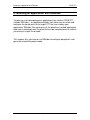
procedure, select RBuilder and the window shown below will appear:
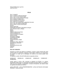
You are now in RBuilder. The screen is divided in 5 different parts:
1.
The tree in area 1 shows you the different peripherals associated with the microcontroller
you are using. It is called the project tree. To use and configure a peripheral, select it in the
tree. The options associated with the selected peripheral will be displayed in area 4.
- 21 -
Building an application with RBuilder
RIDE-ST7
2.
Area 2 shows you which file will be added to your project. This list changes while you are
adding/removing peripherals to your project.
3.
This area displays the datasheet of your microcontroller and the ST7 Software Library
manual.
4.
This area displays the options related to the selected peripheral. This view is called the
Option View.
5.
This part is the online help which guides you through the configuration of your project.
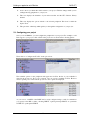
5.3 Configuring your project
Once you are in RBuilder, you can configure the peripherals for your project. For example, to add
I/Os support to your project, click on I/Os in the project tree as shown in the following picture:
Then, click on “Configure and Use IO” in the option view:
The available options for the peripheral will appear and for I/Os, the list of ports available is
added in the project tree. If no port is selected, only one option is available for I/Os. However
when a specific port is selected in the project tree, more options are displayed:
As you can see, each PIN of the PORT can be easily configured using a combo box which lets
you specify if the PIN is either a floating INPUT, a pull-up interrupt INPUT, an open-drain
OUTPUT or a push-pull OUTPUT.
- 22 -
RIDE-ST7
Building an application with RBuilder
Configuring the peripherals is the big part of the process, but you should take care to also
configure the other parts of the project:
• Core (be sure to specify the correct clock speed)
• Memory
• Peripherals
• Interrupts
• Preferences
Some peripherals, like the I/O ports, offer the option to generate sample code. If you check the
option, this sample code will be placed in the main function. This code provides a simple
example of how to use the basic library functions related to the associated peripheral(s).
5.4 Generating your project
Once you are done configuring your project, select Project Generation in the "Actions" menu:
After doing this, RBuilder generates the sample/prototype application code based on the project
configuration, and notifies you when generation is complete. Then RBuilder closes, returning you
to the RIDE-ST7 main window. You can compile the project right away.
Warning: Once the project is generated, there is no way to go back to modify one option and
generate it again. If you find out that you were mistaken about one option, then you have to
restart the project creation process from the beginning.
5.5 Adding your application code
Once you are back in RIDE, source files will be added to your project. Most of the files in your
project are generated from the ST7 Software Library according to the configuration options that
you specified in RBuilder. These files should not need to be edited. Two additional files are
generated:
- 23 -
Building an application with RBuilder
RIDE-ST7
• myprojectmain.c is the main file of the project. In this file, RBuilder generates the
initialization function for all peripherals, the "main()" function and any user requested
functions (for example putchar and getchar for the SCI).
• myprojectint.c contains all the interrupt functions. This file is generated only if the user
selected the use of interrupts in RBuilder. Otherwise it is not part of the project.
5.5.1 The main file
The following is an example of a main file for which the following peripherals have been
selected:
•
I/Os
•
Timer
•
SCI
•
ADC
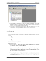
The whole file is generated by RBuilder.
In this file, you can see:
• The "PeriphInit" function (blue arrow) performs initialization for all peripherals
according to the options you selected in RBuilder.
• The "main" function (green arrow) is made of a call to "PeriphInit" to initialize all
peripherals, followed by an infinite loop that contains the application code. RBuilder gives
you the possibility to generate sample code for almost each peripheral. This example
contains code for the ADC, the SPI and I/Os. You just need to add your specific code at
the end of the function. (look for the red arrow)
• The "TERMIO_PutChar" function (brown arrow) is generated when you select
“Generate a putchar function” in RBuilder'
s SCI options section. Since we use Metrowerks
tools in our example, the function is named "TERMIO_PutChar". Using Cosmic tools
we would have "putchar".
- 24 -
RIDE-ST7
/*
/*
/*
/*
/*
/*
/*
Building an application with RBuilder
========================================================== */
Project:
MyProject */
File:
MyProjectMain.c */
Organization:
*/
Author:
(initial version generated by RBuilder) */
Date:
11/23/2004 */
========================================================== */
#include "ST7lib_config.h"
#include <stdio.h>
/*------------------------------------------------------------*/
/*Function:
PeriphInit*/
/*Purpose:
Periph configuration at RESET*/
/*Date:
11/23/2004 */
/*------------------------------------------------------------*/
void PeriphInit ( void ) {
EnableInterrupts;
/* A/D Converter initialization */
ADC_Init(ADC_DEFAULT);
ADC_Select_Channel(0);
/* SCI initialization */
SCI_Init(SCI_DEFAULT_PARAM1, SCI_DEFAULT_PARAM2);
SCI_Select_Baudrate(0xd2);
SCI_Mode(SCI_TX_ENABLE|SCI_RX_ENABLE);
/* 16-bit timers initialization */
TIMERA_Init(TIMER_FCPU_4);
/* Timer A */
TIMERA_IT_Enable(TIMER_OVF_IT_ENABLE);
/* Interrupt controller initialization */
ITC_Init();
/* I/O Port initialization */
IO_Init();
}/*end of
PeriphInit*/
/*------------------------------------------------------------*/
/*Function:
main()*/
/*Purpose:
main routine*/
/*Date:
11/23/2004 */
/*------------------------------------------------------------*/
void main ( void ) {
/*Configure the internal peripherals*/
PeriphInit();
while ( 1 ){
{
/* Sample code for ADC */
- 25 -
Building an application with RBuilder
RIDE-ST7
int Conv_Data1;
/* Select channel 5 CS2:CS1:CS0=101 */
ADC_Select_Channel(5);
/* Start conversion ADON bit is set */
ADC_Enable();
/* Wait till conversion completes */
while(!ADC_Test_Conversn_Complete());
/* Read converted value */
Conv_Data1 = ADC_Conversn_Read();
ADC_Disable();
}
/* Sample code for SCI */
puts("Hello world");
{
/* Sample code for IO */
int read_Data;
/* Read Port A */
read_Data = IO_Read(IO_PORT_A);
/* Set Port A Pin 6 and 7 to high state */
IO_Write(IO_PORT_A, IO_PIN_6|IO_PIN_7 , IO_DATA_HIGH);
}
/*Insert your code here...*/
}
}/*end of main*/
/*------------------------------------------------------------*/
/*Function:
TERMIO_PutChar*/
/*Purpose:
Putchar in polling mode on SCI*/
/*Date:
11/23/2004 */
/*------------------------------------------------------------*/
void TERMIO_PutChar(char c){
if (c == '\n'){
SCI_PutByte ('\r');
while (!SCI_IsTransmitCompleted());
}
SCI_PutByte (c);
while (!SCI_IsTransmitCompleted());
}
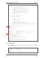
5.5.2 The interrupt file
The following is the interrupt file generated in our example. We selected the use of TIMER A
overflow interrupt.
/*
/*
/*
/*
/*
/*
========================================================== */
Project:
MyProject */
File:
MyProjectInt.c */
Organization:
*/
Author:
(initial version generated by RBuilder) */
Date:
11/23/2004 */
- 26 -
RIDE-ST7
Building an application with RBuilder
/* ========================================================== */
#include "ST7lib_config.h"
/* ---------------------------------------------------------- */
/* Function:
TIMERA_IT_Routine(void) */
/* Purpose:
Interrupt Subroutine for TIMERA Interrupt */
/* Date:
11/23/2004 */
/* ---------------------------------------------------------- */
#ifdef _HIWARE_
/* Test for HIWARE Compiler */
#pragma TRAP_PROC SAVE_REGS
/* Additional reg will be saved */
#else
#ifdef _COSMIC_
/* Test for Cosmic Compiler */
@interrupt
/* Cosmic interrupt handling */
#else
#error"Unsupported Compiler!" /* Compiler Defines not found! */
#endif
#endif
void TIMERA_IT_Routine(void){
/* Insert your code here... */
}/* end of TIMERA_IT_Routine(void) */
The interrupt framework is generated; you only need to fill it in. Keep in mind that an interrupt
needs a flag to be reset when it has been handled.
5.6 Adding your code to the project
Now that you have a project with configured peripherals, you need to add your application code.
To add your source files, select "Project" -> "Add node source/application". This will open a file
selection window that you can use to add your source files in C or assembler.
To rebuild the application, just press "F9" or select "Project" -> "Make All".
Now you are ready to debug your application. If you will be using the simulator, refer to the
chapter, "Debugging with the Simulator". For information about debugging with RLink or an
EMU3 or DVP3 series emulator, go on to the chapter, "Debugging with Hardware Tools".
- 27 -
Debugging with the Simulator
RIDE-ST7
6. Debugging with the Simulator
RIDE-ST7 provides a simulator capable of simulating the most common
ST7 peripherals. The simulator lets you check your code as well as the
interaction between your code and the peripheral before going on to
debug with an in-circuit debugger or emulator.
- 28 -
RIDE-ST7
Debugging with the Simulator
6.1 About the simulator for ST7
RIDE-ST7 supports most of the existing ST7 derivatives to various degrees. The up-to-date list of
supported derivatives and the limitations to the software simulation can be seen in the Target
Options in RIDE.
For the rest of the getting started, we will use a project that uses the following peripheral:
•
I/Os
o
PORT A Pin 1
Output (push/pull)
o
PORT A Pin 2
Output (push/pull)
o
PORT A Pin 3
Output (push/pull)
o
PORT A Pin 4
Output (push/pull)
The following code has been written in the main function:
int toggle = 0; /*This declaration goes at the beginning of the main*/
IO_Write(IO_PORT_A,
IO_Write(IO_PORT_A,
IO_Write(IO_PORT_A,
IO_Write(IO_PORT_A,
IO_PIN_0,
IO_PIN_0,
IO_PIN_0,
IO_PIN_0,
(toggle
(toggle
(toggle
(toggle
==
==
==
==
0)?IO_DATA_HIGH:IO_DATA_LOW);
1)?IO_DATA_HIGH:IO_DATA_LOW);
2)?IO_DATA_HIGH:IO_DATA_LOW);
3)?IO_DATA_HIGH:IO_DATA_LOW);
if(++toggle==4)
toggle = 0;
So you can easily build this project to use the simulator as described in the chapter, "Building an
application with RBuilder".
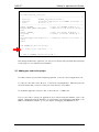
6.2 Launching the simulator
To launch the simulator, type CTRL–F9. If your project has not been built, it will be done
automatically before launching the simulator. Otherwise the simulator is launched directly. The
following window appears to set the debug options:
Make sure that “Virtual Machine” is selected and click OK.
- 29 -
Debugging with the Simulator
RIDE-ST7
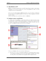
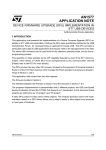
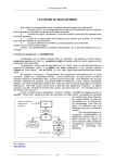
You are now in the simulator. Your RIDE window looks like the following:
The illustration above shows:
1.
The source file as edited in C language or in assembly language. The green circles at the
left indicate lines that contain instructions where you can place breakpoints. The line
highlighted in blue indicates the current PC. That'
s the next instruction to be executed.
2.
The Debugger tab that shows you all the peripherals that are simulated on a given
microcontroller. To see a specific peripheral, double-click on its name. Note the blue line as
in the source window.
3.
The Watch tab which allows to see the watched variables and the local variables.
4.
The toolbar which allows the user to control the simulation. (see more information in the
next section)
5.
The Code window that shows you the instruction to be executed by the simulator. It is a
dump of the memory where the code is located. (see more information below)
6.
The debug tab is a tree where the simulator displays message for the user.
The following columns are available in the Code window:
• Address: The address where the instruction is located.
• Symbol: The name of the symbol, if a symbol is located at this address.
• Code: The byte-code located at this address.
• Mnemonic: The mnemonic corresponding to the byte-code.
• Code Coverage: The number of times the byte-code at this address has been executed
- 30 -
RIDE-ST7
Debugging with the Simulator
6.3 Using the simulator
The simulation is controlled by the simulator toolbar:
1.
Animated mode
each source line.
2.
Display executed lines
When you have executed your application, pressing this button
will change the color of the green circle to blue for each line that has been executed.
3.
Refresh
4.
Reset
5.
Step into
On a function call in a line of the C source code, this button steps into the
called function. If it is not a function call, it goes to the next line in the source code.
6.
Step over
On a function call in a line of the C source code, this button steps over the
called function.
7.
Add watch
8.
Toggle breakpoint
If there is no breakpoint on the current line, RIDE will set a
breakpoint on it. If there is one, the breakpoint will be removed.
9.
Toggle trace
If there is no trace breakpoint on the current line, RIDE will set one. If
there is one, the trace breakpoint will be removed.
The simulator will execute the application slowly with a short pause at
While debugging, pressing this button will refresh the different debug views.
Pressing this button resets the application.
Add a variable to the list of watched variables.
10. Select application
In multi-application simulation, this combo box lets you select which
application you control.
11. Run
Pressing this button launches the application. When the application is running, the
GO button becomes a STOP button. Pressing it will stop the application.
12. Speed
Select the speed at which the simulation must be done.
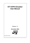
6.4 Simulating a peripheral
To simulate a peripheral, you must open it by clicking on the corresponding item in the peripheral
tree. For example, to simulate the Port A, double click on the following icon:
- 31 -
Debugging with the Simulator
RIDE-ST7
The PORT A view will appear:
This view lets you see the state of each pin of the port. Green indicates a value of one and red a
value of zero. It is possible to connect each pin of the port to a Net, to VCC, the Ground or no
connection. This is done by clicking on the led. The registers also let you control the peripheral.
Once you have created the application described above, start the simulator, open the PORT A and
click on the refresh button as the application is running, you will see the LED blinking.
6.5 Using breakpoints
You can set a breakpoint either in the source file or in the code view. In the code view, first select
the line on which you want to stop. The line will become gray:
- 32 -
RIDE-ST7
Debugging with the Simulator
Then click on the Toggle Breakpoint button and the line will become red, which means that a
breakpoint has been set on this line:
The application will stop running when this line is reached.
You can use the same procedure to set a breakpoint on a line of source code, or you can click on
the green circle in the margin next to the instruction. When you click on the green circle the line
will turn red, indicating that a breakpoint has been set:
- 33 -
Debugging with Hardware Tools
RIDE-ST7
7. Debugging with Hardware Tools
In addition to the Raisonance simulator, RIDE-ST7 can be used with
a number of hardware debugging tools. These tools include the RLink
for in-circuit debugging and the ST7-EMU3 and ST7-DVP3 series
emulators. From a user interface point of view, basic debugging
functions (setting a breakpoint, single-stepping and checking memory
and registers) are identical whether you are using the simulator or a
hardware debugging tool. This chapter tells how to use the available
drivers and the specificity of each.
- 34 -
RIDE-ST7
Debugging with Hardware Tools
7.1 Selecting hardware debugging tools
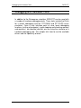
Within RIDE, you can choose your target hardware debugger in the "Options" -> "Debug" menu.
When you check the “Real Machine” radio button, a list of available emulators and other
hardware-based debug tools appears in the drop down “Tools” list.
RIDE-ST7 supports RLink for in-circuit debugging and in-circuit programming and the EMU3
and DVP3 Series emulators.
Select the tool corresponding to your debugging hardware:
If you have an RLink connected to the target ST7 on your application board
RLINK_ST7 via an ICC connector, or if you are using the REva evaluation board, which
includes an embedded RLink.
DVP3_ST7
If you have an ST7-DVP3 series emulator
EMU3_ST7
If you have an ST7-EMU3 series emulator
Then, configure the tool using the "Advanced Options".
If you are using the RLink dongle (or the REva board), continue with the section, "RLink-ST7
programming (ICP) and debugging (ICD) features".
If you are using an EMU3 or DVP3 series emulator, go on to the section, "ST7-DVP3 and EMU3
series emulator features".
- 35 -
Debugging with Hardware Tools
RIDE-ST7
7.2 RLink-ST7 programming (ICP) and debugging (ICD) features
RLink is a USB interface device designed by RAISONANCE. It allows In-Circuit-Programming
(ICP) and In-Circuit-Debugging (ICD) of various microcontrollers, including all the ST7 devices
supported by RIDE-ST7. Some devices with HDFLASH and no debug module do not support
ICD, but you can still use the RLink for programming them (ICP).
With the ST7 devices, RLink uses the In-Circuit-Communication (ICC) protocol from ST to
perform ICP and ICD. RLink uses the standard 10-points ICC connector defined by ST.
In order to use RLink, be sure that you have installed the associated USB driver. Unless you have
specified otherwise, it is installed along with RIDE. If the USB driver has not been installed,
launch the program RLinkUSBInstall.exe. For standard installations of RIDE-ST7, it is located
at:
C:\RIDE\DRIVER\RLINKDRV\RLinkUSBInstall.exe
You can also find it on the installation CD-ROM:
\DRIVER\RLINKDRV\RLinkUSBInstall.exe
After running this program, when you plug RLink in, Windows will recognize it automatically.
RLink supports all the devices that are supported by RIDE. See the up-to-date list in the Target
Options.
Note that the devices with HDFlash and no debug module can be programmed, but not used for
debugging through ICC.
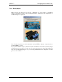
The REva board is a demonstration board that includes a detachable RLink. The whole board can
be powered by the USB through the RLink. The target chip is placed on a interchangeable
daughter board that can include different targets. For RIDE, there is no difference between
operating the REva or using an RLink with another hardware with the ICC connector. For more
information about the demo board itself (schemes, etc.), see its dedicated documentation.
- 36 -
RIDE-ST7
Debugging with Hardware Tools
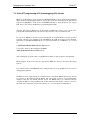
7.2.1 Configuring the RLink
After selecting RLink as your debugging tool (see the section, "Selecting hardware debugging
tools"), click on the "Advanced Options" button to open the Advanced Options dialog box shown
below.
In the Advanced Options, it is critical to check that the selected target corresponds to your chip:
If not, then you must go in the target options to change it. Go back to the RIDE main screen and
select "Target" -> "Options".
Next, indicate the preferred reset method to use when establishing in-circuit communication with
the target ST7:
See the ICC section of your ST7xxxx Datasheet for more information about this. If you do not
know, just leave the default: If the first method fails, then RIDE will try the other and the only
drawback for you is that the reset will take a little more time than needed (less than half a second
more).
Be careful that the external clock is provided (from RLink or another external source) if both
your device'
s default option bytes and current option bytes select the external clock.
To debug your application, confirm that Debug is checked as shown below.
- 37 -
Debugging with Hardware Tools
RIDE-ST7
Uncheck the Debug option if you want to use RLink as a simple programmer, e.g. if you want to
try the application on the ST7 without debugging it. Note that if the Debug option is checked, the
application will be patched (to add code such as reset and trap vectors for debugging) and is only
executed if it is driven by RIDE through RLink. If the Debug option is unchecked, then launching
the debug session will simply program the unpatched code to your ST7 and start execution. This
is useful when using RLink and you don'
t have the source code.
- 38 -
RIDE-ST7
Debugging with Hardware Tools
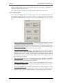
7.2.1.1 RLink jumpers
Make sure that your jumpers are set correctly on the RLink. To do this, click on "View RLink
jumpers configuration for ST7". The following illustrations showing the ST7 configuration for
the RLink jumpers is displayed:
Note: Should the pictures in this documentation and in RIDE be different, assume that those
shown in RIDE are correct.
If you purchased RLink as part of an ST7 kit (such as the REva board for ST7), then the jumpers
should already be correctly set. For this reason, you should only need to adjust these jumpers if
they were accidentally unplugged, or if you are using an RLink that was configured for another
protocol, such as JTAG.
- 39 -
Debugging with Hardware Tools
RIDE-ST7
7.2.1.2 Option Bytes
Next, you need to configure how the ST7'
s option bytes will be handled.
• "Leave as is": the option bytes are not programmed. They retain their current values.
• "Restore default" tells RIDE to erase the option bytes and restore the default value before
loading the FLASH and debugging. If you want to know what value will be loaded when
selecting this option, then click the "Default" button, and you will see the default values in
the "Value to program" section.
• "Program" tells RIDE to erase the options bytes prior to programming the Flash memory,
and to program the option bytes with the value that you have specified in the "Value to
program" section. The option bytes are programmed after the Flash memory has been
programmed.
Value to program:
This is the value that will be written in the option bytes if the "Program" option is selected.
You can change the value by typing the value that you want in the Option Byte 0 and the Option
Byte 1 fields (refer to your ST7xxxx Datasheet for the meanings of these values), or by selecting
"Change value" and configuring the options controlled by each option byte in the "Options"
dialog box (shown below).
Warning: Some option byte values such as those controlling read-out, debug and re-write
protection will prevent any further re-programming of your ST7. Be careful when setting the
option byte values and refer to your ST7xxxx Datasheet for complete descriptions of the options
byte values for your ST7.
The "Options" dialog box shows the meaning of each bit of the option bytes. This can help
prevent errors resulting from typing the wrong value to program to the option bytes. Click on the
field on the right to select option byte settings from a drop-down list of possible settings.
- 40 -
RIDE-ST7
Debugging with Hardware Tools
Finally, clicking "Default" will restore the default value in the edit fields if you think that you
might have typed in an incorrect value.
Note: "Restore default" is the same as "Program" with the default value, but it'
s faster!
7.2.1.3 Instant actions
This section of the "RLink_ST7 options" dialog box allows to carry out the instant actions listed
below without leaving this dialog box. This is useful for testing connections and retrieving
information from the RLink and your ST7, as well as for programming the ST7 and its option
bytes.
• "Connect to RLink and read serial number" is useful for checking that RLink is working
and properly connected and that the USB driver is correctly installed. It also allows you to
read the RLink serial number, which you will be asked for if you contact our support team.
• "Read target option bytes" allows you to read the option bytes currently written in the chip.
Use this also to test the connections and power of the target ST7.
• "Write target option bytes now!" allows to program the option bytes without leaving the
configuration window. When programming them, RIDE takes into account the settings in
the "Option bytes options" section of the dialog box (see the previous section). It will do
nothing if the "Leave as is" option is selected. It will erase and write the default value if the
"Restore default" option is selected. And it will program the value displayed in the edit
fields if "Program" is selected.
• "Erase target now!" allows you to completely erase the target'
s FLASH (writing 0xFF),
option bytes (restoring the default value) and EEPROM (if any). This is the correct way to
remove the read-out protection from a protected device.
• "Dump target FLASH to hex file" reads the contents of the FLASH and writes it in a file in
hex format whose name is derived from the current application'
s name with the extension
.hex (<application name>.hex).
• "Write target FLASH now!" programs the FLASH with the current application'
s hex file
generated by the linker. Then, launches the execution in user mode. When using this
instant action, the code is not patched for debug, even if the "Debug" option is checked.
- 41 -
Debugging with Hardware Tools
RIDE-ST7
7.2.2 Advanced breakpoints
The interface for operating the debugger is exactly the same as for the simulator. However, there
is one feature that is specific to the ST7 devices with a Debug Module: the advanced breakpoints.
Once the debug session has started, if your ST7 device features a Debug Module, you can click
on "Debug" -> "RLINK_ST7" -> "Advanced Breakpoints …" :
If this option does not appear, then your device probably does not have a debug module. You can
check this on the ST7xxxx Datasheet.
This will open the Advanced breakpoints window:
This window allows you to select the break mode and addresses.
Note that if you use the Debug Module to set advanced breakpoints, the debugger will not be able
to use them and, in some cases, will not be able to set standard breakpoints. For instance, if the
target ST7 has HDFlash or if the breakpoint is in sector 0 of an XFlash device, then RIDE will
not be able to set the breakpoint. To allow RIDE to use the Debug Module for standard
breakpoints again, you must go back to the Advanced breakpoints window and disable them.
The advanced breakpoints configuration is discarded at reset.
- 42 -
RIDE-ST7
Debugging with Hardware Tools
7.2.3 Hints and Troubleshooting
7.2.3.1 Example projects
The examples in the REVA folder of the RIDE directory are configured for use with the REva
evaluation board, which includes the RLink. For standard installations they are found at
C:\RIDE\EXAMPLES\ST7\REVA. These examples can also be used with other demonstration
and evaluation boards with a standard ICC connector and the RLink. These are very simple
examples that, for the most part, can be compiled with the demo version of the associated
toolchain (COSMIC, METROWERKS or RAISONANCE) available for download on their
maker'
s website. Some examples are too big to be compiled with the demo versions. These
particular examples include a precompiled version of the application that you can download, run
and debug, but you will not be able to modify it and recompile it. Before using an example, look
at it and make sure that the jumpers on the REVA board are set correctly. (enables for the LEDs,
buttons, SCI, EEPROM, etc.) Usually, there is some important information in comments at the
beginning of the main file. (i.e. the file that contains the "main" function)
7.2.3.2 Testing USB driver, connections and power supplies
To test the USB driver installation and the operation of RLink, use the "Connect to RLink"
instant action. The RLink appears in Windows'device manager under the "Jungo" section when it
is correctly recognized.
To test the connections and power of the target board and ST7, use the "Read option bytes"
instant check. This operation requires RLink to connect to the target ST7, ensuring that it is
powered, correctly connected to RLink, and that the rest of the application board does not
interfere with the communication between RLink and the ST7. (see below)
7.2.3.3 ICCCLK and ICCDATA pins
These two pins are used to communicate between RLink and the target ST7. This means that you
must ensure that the rest of the system (i.e. the other components on the board and the application
in the target chip) does not use them. This also means that your application cannot use these pins
if you plan to debug it with RLink.
These pins'addresses depend on the target ST7. Please refer to the ST7xxx device Datasheet for
more information.
For more information about this, refer to the section, "Building an ICC-compliant application
board".
7.2.3.4 Handling option bytes
Here are the suggested ways to handle the option bytes depending on your project'
s state:
• While you are still debugging the application, you will probably re-program the target ST7
quite often, but the option bytes values will not change much. Since you are always using
the same device, there is no need to re-program the option bytes every time. In this case,
program them once using the "Write target option bytes now!" instant action, and then
select the "Leave as is" option for the debugging sessions.
• When you are in the pre-production phase (debugging is complete and you are
programming multiple ST7s), select "Program", so as to program the option bytes for each
ST7 device. (and uncheck the "Debug" option in the actions for debug session)
- 43 -
Debugging with Hardware Tools
RIDE-ST7
Also, remember that if you protect the FLASH memory against read-out (or write) with the
option bytes, then you will not be able to debug. So even if you already know that your final
application will be protected against read-out, you should not do so during the development
phases of the project when you still need to debug.
7.2.3.5 Command-line programming tool
In the RIDE binaries directory (for standard installations C:\RIDE\BIN), you will find a program
named "ST7_pgm.exe". This is an executable file that allows to erase and program the ST7
connected to the RLink. Call it in a DOS prompt with no arguments in order to see the command
line arguments.
7.2.3.6 Protected addresses
You will notice, in the Code view, that some values have a red square with a white dash next to
them. See the picture below. These values are never updated, and you cannot modify them. These
are “protected addresses”. This means that RIDE will not read them because they are special
peripheral registers that are modified whenever they are read. RIDE never accesses them because
it would interfere with the execution of the application.
7.2.3.7 Limitations of RLink compared to the emulators
The debugging through ICC uses 5 bytes of stack, 2 I/O pins (ICCDATA and ICCCLK). It also
uses about 195 bytes of Flash memory for HDFlash devices and these XFlash devices that do not
feature the advanced version of the ROM-monitor (like the ST7Lite0).
Limitations for XFLASH Targets WITHOUT Debug Module (ST72F26x, ST7FLITE0x,
ST7FLITESx):
• ICCCLK and ICCDATA lines are used for communication between the RLink and the
target ST7. These lines are reserved and should not be used by the application being
debugged.
• 5 stack bytes are used for communication between the RLink and the target. These stack
bytes cannot be used by the application.
• A TRAP vector points to the dedicated RLink-loaded code that is used to manage
breakpoints. A breakpoint is a TRAP instruction patched into the application code. For this
reason, the TRAP vector and TRAP instruction are reserved for RLink.
• During debugging, peripherals continue to run even when the application has been stopped.
• It is not possible to set a breakpoint in sector 0. For this reason, sector 0 should be
configured to its smallest size (0.5Kb) with the option byte.
- 44 -
RIDE-ST7
Debugging with Hardware Tools
• Pressing "Stop" while debugging in RIDE is the same as a reset, and returns the program
counter to the main function.
• Additional Limitation for ST7FLITE0x and ST7FLITES2/5: 195 bytes in Flash memory
are reserved for code that manages communication between RLink and the target ST7.
These bytes cannot be used by the application. This code is loaded when the application is
programmed to the ST7. The programming algorithm places the code as high as possible in
Flash memory. This code never overwrites the interrupt vectors. If there is not enough
space for it, RIDE returns an error message indicating that the user cannot debug the
application.
Limitations for XFLASH Targets WITH Debug Module (ST7FLITE1x, ST7FLITE2x,
ST7FLITE3x):
• ICCCLK and ICCDATA lines are used for communication between the RLink and the
target ST7. These lines are reserved and should not be used by the application being
debugged.
• 5 stack bytes are used for communication between the RLink and the target. These stack
bytes cannot be used by the application.
• A TRAP vector points to the dedicated RLink-loaded code that is used to manage
breakpoints. A breakpoint is a TRAP instruction patched into the application code. For this
reason, the TRAP vector and TRAP instruction are reserved for RLink.
• During debugging, peripherals continue to run even when the application has been stopped.
• It is possible to set up to 2 breakpoints on sector 0, or 1 advanced breakpoint.
Limitation for HDFLASH Targets:
• 5 stack bytes are used for communication between the RLink and the target. These stack
bytes cannot be used by the application.
• 195 bytes in Flash memory are reserved for code that manages communication between
RLink and the target ST7. These bytes cannot be used by the application. This code is
loaded when the application is programmed to the ST7. The programming algorithm places
the code as high as possible in Flash memory. This code never overwrites the interrupt
vectors. If there is not enough space for it, RIDE returns an error message indicating that
the user cannot debug the application.
• If the device does not have a debug module (see the ST7xxxx Datasheet), In-Circuit
Debugging is not possible.
- 45 -
Debugging with Hardware Tools
RIDE-ST7
7.3 ST7-DVP3 and EMU3 series emulator features
RIDE-ST7 also supports the entry-level ST7-DVP3 and full-featured ST7-EMU3 series
emulators. These emulators connect your PC to your application board in place of the target ST7,
for debugging. Emulators are available for all target ST7s supported by RIDE. For complete
information about emulator features, refer to the ST7-DVP3 Emulator User Manual or the ST7EMU3 Emulator User Manual.
7.3.1 Configuration
In the Advanced Options dialog box, select the communication port (parallel, USB or Ethernet)
that your debugging hardware is connected to. For Ethernet connection, you can type the
emulator'
s IP address directly in the Connection Port field:
Note: Information about assigning an IP address is found in the ST7-EMU3 Emulator User
Manual.
Use the "Debug" -> "Start" command to connect and configure the microcontroller according to
your project'
s Target Settings.
7.3.2 Trace Recording
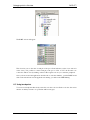
For both DVP3 and EMU3 series emulators, you can use the Trace window to control and view
the contents of the trace buffer.
To turn the trace on and off, select "Debug" -> "Trace" -> "Options" and click on the appropriate
radio button in the Trace dialog box:
• Off to disable trace
• Continual to enable trace
- 46 -
RIDE-ST7
Debugging with Hardware Tools
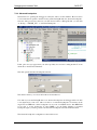
To open the trace window, from the main menu select the command "Debug" -> "Trace" ->
"View".
The Trace window contains a table with several columns, which together form a single trace
record. The following types of information can be recorded and displayed:
• N°: corresponds to the number of the trace record in the buffer. The oldest record in the
trace buffer is always record number "1".
• PC: the memory location accessed.
• Source: the instruction in assembly language mnemonics, if this is a Fetch instruction
cycle.
• Data: the hexadecimal value on the data bus.
• Events: the type of microprocessor event-for example, stack read, stack write, data read,
data write, etc.
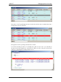
For DVP3 series emulator these additional columns are available:
• Memory: the type of memory access (i.e. either read/write/fetch or invalid).
• Trigger Input: the value of the TRIGIN signal (input pin located on the DVP).
• Probe: The values of the signals output from the probe pins located on the DVP.
For EMU3 series emulator the additional columns are:
• t: the value in nanoseconds of the time marker at this event.
• dt: the delta time between this recording and the next one.
• Timestamp Event: signals the occurrence of events that affect the validity of the value in
the time column-in particular
• Trace discontinuity: indicates that the trace record in the buffer is not continuous. This is
the case when the trace is turned on or off using an advanced breakpoint or from the standalone viewer, to record only certain events.
• TIN (Trigger IN): external Trigger input.
- 47 -
Debugging with Hardware Tools
RIDE-ST7
• AI (Analyzer Input): input from the Analyzer input connector on the EMU3 probe.
• Advanced Breakpoints: shows the level and the logic states of the Bus Event
Machine (BEM) as they become TRUE. These are reported in the form BEM l[14] [e1 / e2 / if / e3 / e4 / else]. For example: BEM l2 e1 if indicates that on Level 2 of
the sequencer, Event 1 is TRUE and at the same time the condition IF is TRUE (i.e.
only one event is necessary to fulfill the IF condition in this case).
7.4 EMU3 series emulator special features
The EMU3 series emulators provided Performance Analysis and Advanced Breakpoint
capabilities.
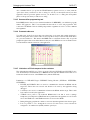
These special features are available during the debug session from the popup menu command
"Debug" -> "EMU3_ST7":
For more information about these features that are specific to the ST7-EMU3 series emulators,
please refer to the help files:
addonperf.chm (for Performance Analysis) and addonbem.chm (for Advanced Breakpoints). For
standard installations of RIDE, these are found in the directory: C:\RIDE\BIN\EMU3\HELP
- 48 -
RIDE-ST7
Building an ICC-compliant application board
8. Building an ICC-compliant application board
In-Circuit Debugging (ICD) and In-Circuit Programming (ICP) are
applications of the In-Circuit Communication (ICC) protocol
developed by ST for ST7 microcontrollers. With the necessary
connection hardware, this protocol allows you to read and write to
your ST7's Flash memory, and control the running of your application
on your microcontroller.
This protocol is used by RLink and the other ST7 in-circuit debuggers
and programmers.
To take advantage of ICC, you must integrate an ICC connector into
your application hardware when you start developing your
application. To help you implement ICP and ICD in the development
of your application, this chapter provides a summary of points you
should consider when installing an ICC connector.
The REva board features an ICC connector. Refer to its schematics
in the REva User Guide for an example of a correct connection.
- 49 -
Building an ICC-compliant application board
RIDE-ST7
8.1 ICC Connector
To connect to your application board for ICP and ICD, you need to install a 10-pin, HE-10 type
connector (also called an ICC Connector) and ensure the appropriate connections to your ST7.
This connector receives the ICC cable and relays the signals required for ICP and ICD to your
ST7.
The table below describes the ICC connector and its pins usage:
Connector
Pin
(and pin number)
ST7 Pin (see pin number
on device datasheet)
Function
GND (1, 3, 5, 10)
GND
Ground
VDD_APPLI (7)
VDD
Device power supply
ICCDATA (2)
ICCDATA
ICC input/output serial data pin
ICCCLK (4)
ICCCLK
ICC input serial clock pin
ICCRESET (6)
RESET
Device reset
ICCSEL/VPP (8)
ICCSEL/VPP
Programming voltage and ICC selection
ICCOSC (9)
OSC1 or OSCIN
Main clock input for external clocking (optional)
8.1.1 ICCDATA and ICCCLK pins
These pins are used to transfer data between the RLink and the target microcontroller.
As soon as the programmer’s ICC connector is connected to the application board, the ICCDATA
and ICCCLK pins must not be used by other application devices, even if an ICC session is not in
progress. If the application uses these pins as inputs, isolation such as a serial resistor must be
implemented to prevent other application devices from forcing a signal on either of these pins.
The application board must not drive current in excess of 1mA. If the ICCDATA and ICCCLK
pins are only used as outputs by the application, no signal isolation is necessary.
For ST7 without an ICCSEL pin, during normal operation the ICCCLK pin must be pulled-up
internally or externally (10ΚΩ pull-up required in noisy environments). This is to avoid entering
ICC mode unintentionally during a reset.
8.1.2 RESET pin
This pin is used to reset the target microcontroller from the host PC through the RLink.
During an ICC session, you must ensure that the RLink controls the ST7’s RESET pin so that no
external reset is generated by the application board. This can lead to a conflict if the application
reset circuitry signal exceeds 5mA (push-pull output or pull-up resistor <1KΩ). To avoid such
conflicts, a Shottky diode can be used to isolate the application reset circuit.
8.1.3 ICCSEL/VPP pin
This pin is used on certain ST7 derivatives for supplying a 12V programming voltage and/or for
entering ICC (program) mode.
- 50 -
RIDE-ST7
Building an ICC-compliant application board
The application should include a pull-down resistor not lower than 10KΩ.
8.1.4 ICCOSC pin
This pin is used for the RLink to provide an external clock to the target microcontroller.
The ICCOSC pin of the ICC connector must be connected to the ST7’s OSC1 or OSCIN pin if
the clock is not provided by the application, or if the application clock source is not programmed
in the option byte. This connection allows you start communication with your ST7 for in-circuit
debugging and/or programming using the "Ignore Option Bytes" option. When doing so, your
RLink provides a clock source to initiate communication with the ST7.
The RLink provides a clock source at a frequency of 12MHz.
For ST7 devices with multi-oscillator capability, when the ICCOSC pin is connected, the OSC2
pin should be grounded.
8.1.5 VDD_APPLI pin
This pin is used by tools with a power supply follower, such as RLink. This connection is needed
by the power supply follower to detect the supply voltage and power the RLink'
s I/Os
accordingly.
- 51 -