1
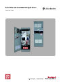
PowerFlex 700 and 700H Packaged Drives
Technical Data
PowerFlex 700 and 700H Packaged Drives Technical Data
Overview
The heart of every PowerFlex 700/700H packaged drive package is a PowerFlex Adjustable Frequency Drive. The
packaged drives program provides PowerFlex700/700H drives packaged with a much larger offering of factory mounted
options than what is normally available with a standard product.
This document contains information related to the Rockwell Automation PowerFlex 700/700H packaged drives program
and is intended to provide information related to drive packaging features, option descriptions, dimensional and layout
information. See Options on page 9 for information on specific drives.
Important: While this information may be useful in specifying and application of a Packaged PowerFlex 700/700H AC
drive, be advised that this information is for Reference Only and subject to change at any time.
Table of Contents
Catalog Number Explanation. . . . . . . . . . . . . . . . . . . . . . . . . . . . . . . . . . . . . . . . . . . 3
Specifications. . . . . . . . . . . . . . . . . . . . . . . . . . . . . . . . . . . . . . . . . . . . . . . . . . . . . . . 8
Options . . . . . . . . . . . . . . . . . . . . . . . . . . . . . . . . . . . . . . . . . . . . . . . . . . . . . . . . . . . 9
Sample Power Distribution Schemes - 6 Pulse . . . . . . . . . . . . . . . . . . . . . . . . . . . 9
Sample Power Distribution Schemes - 18 Pulse . . . . . . . . . . . . . . . . . . . . . . . . . 10
Power Disconnect . . . . . . . . . . . . . . . . . . . . . . . . . . . . . . . . . . . . . . . . . . . . . . . . 11
Control Power . . . . . . . . . . . . . . . . . . . . . . . . . . . . . . . . . . . . . . . . . . . . . . . . . . . 11
Output Power. . . . . . . . . . . . . . . . . . . . . . . . . . . . . . . . . . . . . . . . . . . . . . . . . . . . 11
Bypass. . . . . . . . . . . . . . . . . . . . . . . . . . . . . . . . . . . . . . . . . . . . . . . . . . . . . . . . . 12
Enclosure . . . . . . . . . . . . . . . . . . . . . . . . . . . . . . . . . . . . . . . . . . . . . . . . . . . . . . 12
Power Conditioning . . . . . . . . . . . . . . . . . . . . . . . . . . . . . . . . . . . . . . . . . . . . . . . 12
Control and Feedback - Auxiliary Contacts . . . . . . . . . . . . . . . . . . . . . . . . . . . . . 13
Door Mounted Operator Devices. . . . . . . . . . . . . . . . . . . . . . . . . . . . . . . . . . . . . 13
Output Metering. . . . . . . . . . . . . . . . . . . . . . . . . . . . . . . . . . . . . . . . . . . . . . . . . . 14
Codes and Standards . . . . . . . . . . . . . . . . . . . . . . . . . . . . . . . . . . . . . . . . . . . . . 14
Electronic Drawings. . . . . . . . . . . . . . . . . . . . . . . . . . . . . . . . . . . . . . . . . . . . . . . 14
Enclosure Information . . . . . . . . . . . . . . . . . . . . . . . . . . . . . . . . . . . . . . . . . . . . . 15
Enclosure Information . . . . . . . . . . . . . . . . . . . . . . . . . . . . . . . . . . . . . . . . . . . . . . . 15
Guidelines . . . . . . . . . . . . . . . . . . . . . . . . . . . . . . . . . . . . . . . . . . . . . . . . . . . . . . 15
Dimensions . . . . . . . . . . . . . . . . . . . . . . . . . . . . . . . . . . . . . . . . . . . . . . . . . . . . . 15
Approximate Watts Loss . . . . . . . . . . . . . . . . . . . . . . . . . . . . . . . . . . . . . . . . . . . . . 18
Dimension Drawings - 6 Pulse. . . . . . . . . . . . . . . . . . . . . . . . . . . . . . . . . . . . . . . . . 19
Dimension Drawings - 18 Pulse. . . . . . . . . . . . . . . . . . . . . . . . . . . . . . . . . . . . . . . . 40
Reference Materials
For additional PowerFlex 700 and 700H data and general drive information, refer to the following publications.
Title
PowerFlex 700 Technical Data
PowerFlex 700 User Manual
PowerFlex 700 Installation Instructions - Frame 0…6
PowerFlex 700H Technical Data
PowerFlex 700H Installation Manual - Frames 9…14
PowerFlex 700H Programming Manual
PowerFlex Reference Manual
PowerFlex 700/700H 18 Pulse CSI Specification
Wiring and Grounding Guidelines for PWM AC Drives
Preventive Maintenance of Industrial Control and Drive System Equipment
Safety Guidelines for the Application, Installation and Maintenance of Solid State Control
2
Publication
Available Online at…
20B-TD001…
www.rockwellautomation.com
/literature
20B-UM002…
20B-IN019…
20C-TD001…
PFLEX-IN006…
20C-PM001…
PFLEX-RM004…
PFLEX-SR001…
DRIVES-IN001…
DRIVES-TD001…
SGI-1.1
Publication PFLEX-TD001E
PowerFlex 700 and 700H Packaged Drives Technical Data
Catalog Number Explanation
PowerFlex 700
Contact your Rockwell Automation representative for product option rules.
Position
1-3
4
5-7
8
9
10
11
12
13
14
15
16
17-18
21B
D
2P1
A
3
A
Y
N
A
R
C
0
NN NN
a
b
c
d
e
f
g
h
i
j
k
l
m
19-20
22-23
-
n
o
a
e
i
Drive
HIM
Emission
Code
Type
21B
PowerFlex 700
b
Voltage Rating
Code
Voltage
Ph.
Pulse
Type
D
480V AC
3
6
SA
U
480V AC
3
18
SA
c1
Code
Version
Code
Rating
0
No HIM - Blank Plastic Inserted (Drive
Mounted)
A§
Filter w/CM Choke
3
Full Numeric LCD HIM (Drive Mounted)
5
Programmer Only LCD HIM (Drive
Mounted)
A
Drive Mounted LCD Full Numeric & Door
Mounted Bezel w/Blank Cover,
NEMA/UL Type 1
C
Door Mounted Bezel w/LCD Full
Numeric, NEMA/UL Type 1
E
Drive Mounted LCD Full numeric & Door
Mounted Bezel w/LCD Programmer
Only, NEMA/UL Type 1
Rating
Drive Mounted LCD Full Numeric & Door
Mounted LCD Full Numeric, NEMA/UL
Type 1/12
Output @ 480V, 60 Hz Input
Code
Amps ‡
ND Hp
HD Hp
1P1
1.1
0.5
0.33
2P1
2.1
1.0
0.75
3P4
3.4
2.0
1.5
5P0
5
3.0
2.0
F
Drive Mounted LCD Full Numeric & Door
Mounted Programmer Only, NEMA/UL
Type 1/12
G
J
Door Mounted Full Numeric LCD HIM,
NEMA/UL Type 1/12
K
Door Mounted NEMA/UL Type 1/12
Programmer Only
L
Door Mounted NEMA/UL Type 1/12
Bezel, No HIM, Blank Cover Inserted,
NEMA/UL Type 1/12
CM Choke Only
C
§ Standard for 480V, 6 pulse.
Standard for 480V, 18 pulse.
j
Comm Slot
Code
Version
C
ControlNet (Coax)
D
DeviceNet
E
EtherNet/IP
I
Interbus
P
PROFIBUS
R
Remote I/O
S
RS485
N
None
H
HVAC
8P0
8
5.0
3.0
011
11
7.5
5.0
014
14
10
7.5
022
22
15
10
027
27
20
15
034
34
25
20
040
40
30
25
052
52
40
30
f
065
65
50
40
Documentation
077
77
60
50
Code
Type
l
096
96
75
60
A
User Manual (Standard)
125
125
100
75
Feedback
156
156
125
100
180
180
150
125
248
248
200
150
‡ Normal duty continuous amps.
ND
g
k
I/O
Code
Control
C
Vector
I/O Volts
24V DC
D
Vector
115V AC
Code
Type
0
None
1
12V/5V Encoder
Brake
Code
w/Brake IGBT
Y
Yes (Standard for Frames 0…3)
m
N
No (Standard for Frames 4…6)
Reserved
d
Enclosure
Enclosure
h
n
A
IP20, NEMA/UL Type 1
Brake Resistor
Special Firmware
H
IP54, NEMA/UL Type 12 w/Fan & Filter
Code
w/Internal Resistor
Code
Function
B
NEMA/UL Type 1 MCC
Y
Yes (Frames 0…2 Only)
NN
None
N
No (Standard)
Code
6 Pulse Drives Only - Floor Mount Rittal
Enclosure (Frames 5 & 6) or Wall Mount
Hoffman Enclosure (Frames 0…4).
18 pulse drives only.
Publication PFLEX-TD001E
3
PowerFlex 700 and 700H Packaged Drives Technical Data
o
Options
Code
Description
-ND §
Normal Duty
-HD §
Heavy Duty
-B0 §
Bypass Not Required
-B1/B51 §
-B2/B52
Manual Bypass
Auto Bypass
-C1 §
Drive Only Control Power
-C5 §
115V User Supplied Control Power
-E9
Nameplate, Door Mounted
-G1
Johnson Controls Metasys® Interface
-J1
Aux. Contacts, Control Power On
-J2
Aux. Contacts, Drive Fault
-J3
Aux. Contacts, Alarm
-J4
Aux. Contacts, Run
-J5
Aux. Contacts, At Speed
-J8/J58
Motor Heater Control, Remote Power (180W Max.)
-L1
3% Input Line Reactor
-L2
3% Output Load Reactor
-M3
Motor Run Meter, Drive/Bypass
-N1
Motor Run Meter, Drive/Bypass
-N2
Isolated Analog Input, 4-20 mA
-N3
Isolated Analog Output, 0-10V DC
-N5
Building Mng. Control Interface
-P1 §
No Input Protection
-P2 §
Input Fuses, Drive
-P3 §
Circuit Breaker, Drive
-P4 §
Circuit Breaker, Drive/Bypass Mode
-P6 §
Fused Disconnect Switch, Drive
-P7 §
Fused Disconnect Switch, Drive/Bypass Mode
-P8 §
Disconnect Switch (Non-Fused), Drive/Bypass Mode
-P10 §
Fuse Block (No Fuses), Bypass Mode Only
-P11
Contactor, Drive Input
-P12
Contactor, Drive Output
-S1/S51
H/O/A S.S. (Start/Stop/Spd. Ref.)
-S9/S59
Run Pilot Light
-S10/S60
Drive Fault Pilot Light
-S11/S61
At Speed Pilot Light
-S12/S62
Drive Alarm Pilot Light
-S13/S63
Control Power On Pilot Light
-S14/S64
Drive & Bypass Mode Pilot Lights
-S15/S65
Bypass Mode & Auto Bypass En. P.L.
-S16/S66
Drive/Bypass (B1/B51, if present) Disable Mushroom P.B.
-S17/S67
Motor Fault Pilot Light
-S18/S68
Speed Potentiometer (1-Turn)
§ Must select either -ND or HD, Bypass option -B0 or B1, Power
Disconnecting Means option -P1, P2, P3, P4, P6, P7, P8 or P10 and
Control Power option -C1 or C5.
Denotes 800F/800T device. When selecting multiple options, Do Not
combine 800F and 800T devices (all devices must be the same type).
Available only with 480V, 6 Pulse drives.
Standard with 480V, 18 Pulse drives.
Available only with 480V, 18 Pulse drives.
4
Publication PFLEX-TD001E
PowerFlex 700 and 700H Packaged Drives Technical Data
PowerFlex 700H
Contact your Rockwell Automation representative for product option rules.
Position
1-3
4
5-7
8
9
10
11
12
13
14
15
16
17-18
19-20
21C
D
261
B
0
A
N
N
B
N
B
0
NN
NN
a
b
c
d
e
f
g
h
i
j
k
l
m
n
22-23
-
o
a
d
h
Drive
Enclosure
Brake Resistor
Code
Type
21C
PowerFlex 700H
ND
Code
Enclosure
Code
w/Resistor
B
IP 20, NEMA/UL Type 1, MCC
Style
N
No
b
e
i
Voltage Rating
HIM
Internal EMC Filter & Common Mode Choke
Code
Voltage
Ph.
Pulse
Code
Operator Interface
Code
CE Filter
D
480V AC
3
6
0
Drive Mounted Blank Cover
B‡
Yes
CM Choke
No
U
480V AC
3
18
M
Door Mounted Programmer Only
(NEMA/UL Type 1)
N
No
No
P
Door Mounted w/LCD Full Numeric
(NEMA/UL Type 1)
Must be selected with 480V, 18 pulse drives.
‡ Must be selected with 480V, 6 pulse drives.
c
Rating ♣
480V, 60Hz Input
Code
j
f
Internal Communication Adapters
Amps - ND (HD)
Hp - ND (HD)
261
240 (180)
200 (150)
300
300 (240)
250 (200)
385
361 (302)
300 (250)
460
414 (361)
350 (300)
500
500 (414)
450 (350)
590
590 (515)
500 (450)
g
H
HVAC
650
590 (590)
500 (500)
Internal Brake IGBT
I
Interbus
730
708 (590)
600 (500)
Code
w/Brake IGBT
N
820 ‡
820 (708)
700 (600)
N
No
P
PROFIBUS
920 ‡
920 (820)
800 (700)
R
Remote I/O
1K0 ‡
1030 (920)
900 (800)
S
RS485
Documentation
Code
Type
A
User Manual
Code
Version
B
BACnet MS/TP
C
ControlNet (Coax)
D
DeviceNet
E
Ethernet/IP
♣ 700H drives include an input line reactor as
standard.
Current ratings are matched to NEC or typical
motor ampere requirements.
Available only with 480V, 18 pulse drives.
‡ Available only with 480V, 6 pulse drives.
Publication PFLEX-TD001E
None
k
Control and I/O
Code
I/O Volts
B
115V AC
5
PowerFlex 700 and 700H Packaged Drives Technical Data
l
o
Feedback
Options
Code
Type
Code
Description
0
None
-ND §
Normal
-HD §
Heavy
-B0 §
Bypass Not Required
-B1/B51 §
m
-B2/B52
Special Options
Code
Type
NN
None
n
Special Options
Code
Type
NN
None
Manual Bypass
Auto Bypass
-C1 §
Drive Only Control Power
-C5 §
115V User Supplied Control
Power
-E9
Nameplate, Door Mounted
-J1
Aux. Contacts, Control Power On
-J2
Aux. Contacts, Drive Fault
-J3
Aux. Contacts, Alarm
-J4
Aux. Contacts, Run
-J5
Aux. Contacts, At Speed
-J8/J58
Motor Heater Control, Remote
Power (180W Max.)
-M3
Motor Run Meter, Drive/Bypass
-N1
Isolated Analog Input, 0-10V DC
-N2
Isolated Analog Input, 4-20 mA
-N3
Isolated Analog Output, 0-10V
DC
-P1 §‡
No Input Protection
-P2 §
Input Fuses, Drive
-P3 §
Circuit Breaker, Drive
-P4 §
Circuit Breaker, Drive/Bypass
Mode
-P6 §
Fused Disconnect Switch, Drive
-P7 §‡
Fused Disconnect Switch,
Drive/Bypass Mode
-P8
§
-P10
Disconnect Switch (Non-Fused),
Drive/Bypass Mode
Fuse Block (No Fuses), Bypass
Mode Only
-P11 ‡
Contactor, Drive Input
-P12 ‡
Contactor, Drive Output
-S1/S51
H/O/A S.S. (Start/Stop/Spd. Ref.)
-S9/S59
Run Pilot Light
-S10/S60
Drive Fault Pilot Light
-S11/S61
At Speed Pilot Light
-S12/S62
Drive Alarm Pilot Light
-S13/S63
Control Power On Pilot Light
-S14/S64
Drive & Bypass Mode Pilot Lights
-S15/S65
Bypass Mode & Auto Bypass En.
P.L.
-S16/S66
Drive/Bypass (B1/B51, if present)
Disable Mushroom P.B.
-S17/S67
Motor Fault Pilot Light
-S18/S68
Speed Potentiometer (1-Turn)
§ Must select either -ND or HD, Bypass option B0 or B1/B51, Power Disconnecting Means
option -P1, P2, P3, P4, P6, P7 or P8 and
Control Power option -C1 or C5.
Denotes 800F/800T device. When selecting
multiple options, Do Not combine 800F and
800T devices (all devices must be the same
type).
Available only with 480V, 18 pulse drives.
‡ Available only with 480V, 6 pulse drives.
6
Publication PFLEX-TD001E
PowerFlex 700 and 700H Packaged Drives Technical Data
Additional Catalog Number Notes
Voltage Codes (Position 4/b)
• 18 Pulse Ratings – This option is available as voltage code U and provides a “Low Harmonic” input current draw to
allow for compliance with IEEE-519 specifications. Available starting at 30 Hp and higher, this option uses a
“Common Bus” DC input drive combined with 18 pulse phase shifting transformer and separate rectifier circuit. All 18
pulse packaged drives are built in MCC type enclosures as the standard offering.
Enclosure Types (Position 8/d)
• Packaged Drives are assembled in NEMA/UL Type 1, 4 or 12 enclosures. Each enclosure type lends itself to a
particular type of protection and environment. The enclosures detailed below do not normally protect electrical
equipment from condensation, corrosion or contamination which may occur within the enclosure or enter via the
conduit or unsealed openings. Users must make adequate provisions to safeguard against such conditions, and satisfy
themselves that the equipment is properly protected. For further information on criteria associated with NEMA
enclosure ratings, refer to NEMA Standards Publication NO. 250-1991.
- IP20 NEMA/UL Type 1 enclosures are intended for indoor use primarily to provide a degree of protection against
contact with the enclosed equipment in locations where unusual service conditions do not exist. The enclosures are
designed to meet the rod entry and rust resistance design tests. Openings in the enclosure door or sides and/or fans on
the door(s) or sides allow for free exchange of inside and outside air.
A = NEMA/UL Type 1 (Enclosure style not specified)
B = NEMA/UL Type 1 MCC Style. Note - No through bus provided.
- IP54 NEMA/UL Type 12 enclosures are intended for indoor use primarily to provide a degree of protection against
dust, falling dirt and dripping non-corrosive liquids. They are designed to meet drip, dust and rust resistance tests.
There may be ventilation openings on the enclosure to allow free exchange of inside and outside air. Closed loop
auxiliary cooling may be required for higher Hp ratings. Specifications calling for NEMA-12 ventilated enclosures
should be reviewed with the factory.
H = NEMA/UL Type 12 Ventilated - with fans if needed.
- IP65 NEMA/UL Type 4 enclosures are intended for indoor or outdoor use primarily to provide a degree of protection
against windblown dust and rain, splashing water, and hose directed water, and to be undamaged by the formation of
ice on the enclosure. They are designed to meet hose-down, dust, external icing and rust resistance design tests.
Doors and openings will be gasket sealed. There are no ventilation openings within the enclosure to allow for free
exchange of inside and outside air. Closed loop auxiliary cooling may be required for higher Hp ratings.
D = NEMA/UL Type 4 Indoor use only.
E = NEMA/UL Type 4 Outdoor - Accommodations made for solar gain.
Note - HIM selection may be limited on NEMA/UL Type 4 enclosure designs.
Publication PFLEX-TD001E
7
PowerFlex 700 and 700H Packaged Drives Technical Data
Specifications
In most cases the general specifications of a packaged drive package will match those of a stand-alone drive. Refer to the
Reference Materials section below for further information. Agency Certifications can be found on page 14.
Maximum Short Circuit Drive Package - The short circuit interrupt capability of any drive package will be based upon the
specific combination of the options chosen.
Duty Cycle
• ND = Normal Duty Rated.
100% continuous current
110% current for 1 minute
150% for 3 seconds
• HD = Heavy Duty Rated.
100% continuous current
150% current for 1 minute
200% for 3 seconds
Important: The Packaged Drive duty cycle rating is located on the drive “System” data nameplate. The standard drive
is used as a component in the enclosure and may indicate ratings on its nameplate that differ from the
“System” data nameplate. The packaged drive system rating may be limited by other components sized for
NEC/typical motor ratings. In all cases the system nameplate data supersedes any component nameplate
information. Unless otherwise stated, Normal Duty Rated packaged drives can not be used on Heavy Duty
applications and Heavy Duty drives can not be used on Normal Duty Rated applications, regardless of the
information on the standard drive component nameplate.
8
Publication PFLEX-TD001E
PowerFlex 700 and 700H Packaged Drives Technical Data
Options
Sample Power Distribution Schemes - 6 Pulse
The power distribution schemes shown below are for typical configurations and offered as suggestions only. Actual
specified configurations may vary with accepted design practices or code restrictions.
Breaker
Option -P3
Bypass/System
Fuse & Disconnect
Option -P7
Fuse & Disconnect
Option -P6
PowerFlex
700/700H
Drive
Input Contactor
Option -P11
PowerFlex
700/700H
Drive
PowerFlex
700/700H
Drive
Output Contactor
Option -P12
Output Contactor
Option -P12
Breaker
Option -P3
AC
Motor
Bypass
Option -B1 or B51
add -B2 or B52
if Auto Bypass is
Required
AC
Motor
Bypass/System
Breaker Option -P4
Input Contactor
Option -P11
Input Contactor
Option -P11
PowerFlex
700/700H
Drive
Bypass
Option -B1 or B51
add -B2 or B52
if Auto Bypass is
Required
AC
Motor
No Input Protection
Option -P1
User Supplied
Disconnect
Publication PFLEX-TD001E
PowerFlex
700/700H
Drive
Bypass
Option -B1 or B51
add -B2 or B52
if Auto Bypass is
Required
Output Contactor
Option -P12
AC
Motor
No Input Protection
Option -P1
Input Contactor
Option -P11
PowerFlex
700/700H
Drive
Output Contactor
Option -P12
AC
Motor
User
Connection
Point
User Supplied
Protection &
Disconnect
No Input Protection
Option -P1
Drive Input Fuses
Option -P2
PowerFlex
700/700H
Drive
AC
Motor
PowerFlex
700/700H
Drive
AC
Motor
User Supplied
Protection &
Disconnect
User
Connection
Point
AC
Motor
User
Connection
Point
9
PowerFlex 700 and 700H Packaged Drives Technical Data
Sample Power Distribution Schemes - 18 Pulse
Bypass/System
Disconnect
Option -P8
Input Fuses, Drive
Required Option -P2
Bypass/System Circuit
Breaker Option -P4
Input Fuses, Drive
Required Option -P2
Bypass Fusing
Option -P10
Input Contactor
Option -P11
Input Contactor
Option -P11
PowerFlex
700/700H
Drive
PowerFlex
700/700H
Drive
Manual Bypass
Option -B1
Add -B2 if
Auto Bypass
is Required
Manual Bypass
Option -B1
Add -B2 if
Auto Bypass
is Required
AC
Motor
User
Connection
Point
AC
Motor
User
Connection
Point
Circuit Breaker, Drive
Option -P3
Fused Disconnect Switch
Option -P6
Fused Disconnect Switch
Option -P6
Input Fuses, Drive
Option -P2
Input Contactor
Option -P11
PowerFlex
700/700H
Drive
PowerFlex
700/700H
Drive
PowerFlex
700/700H
Drive
Contactor, Drive Output
Option -P12
Contactor, Drive Output
Option -P12
AC
Motor
AC
Motor
10
AC
Motor
Publication PFLEX-TD001E
PowerFlex 700 and 700H Packaged Drives Technical Data
Power Disconnect
Option
P1
No Input Protection
P2
P3
P4
P6
P7
P8
P10
P11
Description
This option identifies that no drive input protection is supplied. Documentation to reflect input
disconnection and protection is customer supplied.
Drive Input Fuses
Drive input fusing provides branch circuit protection when in the drive mode of operation.
Drive Circuit Breaker
This option is for disconnecting drive power only. Most ratings will use a motor circuit protector (MCP)
type breaker. Where MCP's are not available, a thermal magnetic type breaker will be provided. All
switches are through the door (with the exception of MCC style enclosures which use a flange style
switch) and include handle operators, door interlocking and are pad-lockable.
Drive/Bypass Mode Circuit Breaker This option is for disconnecting all input power to the cabinet (does not include remote power sources).
Most ratings will use a motor circuit protector (MCP) type breaker. Where MCP's are not available, a
thermal magnetic type breaker will be provided. All switches are through the door (with the exception of
MCC style enclosures which use a flange style switch) and include handle operators, door interlocking
and are pad lockable.
Drive Disconnect Switch and Fuses This option is for disconnecting drive power only. A through the door (with the exception of MCC style
enclosures which use a flange style switch) pad lockable disconnect switch with fuses is provided.
Drive/Bypass Mode Fused
This option is for disconnecting all input power to the cabinet (does not include remote power sources)
Disconnect Switch
and provides branch circuit protection. A through the door (with the exception of MCC style enclosures
which use a flange style switch) pad lockable disconnect switch with fuses is provided
Drive/Bypass Mode Non-Fused
This option is for disconnecting all input power to the cabinet (does not include remote power sources).
Disconnect Switch
A through the door (with the exception of MCC style enclosures which use a flange style switch) pad
lockable disconnect switch is provided
Bypass Mode Motor Fuse Block
This option provides a fuse block only. Fuses must be customer supplied and installed. This option is
used in conjunction with the bypass option for motor branch circuit protection. Fuse block will accept
class L dual element time delay fuse.
Drive Input Contactor
A contactor (where available) is provided between the AC line and the drive. The contactor will close
on power up using A-B circuitry, or may be alternately controlled by customer supplied remote contact
closure logic.
Note: The P11 option “alternate contact circuit” is not intended to be used as a Start / Stop circuit.
Control Power
Option
C1
Drive Only Control Power
C5
User Supplied Control Power
Description
This option provides a fused (two primary and one secondary) control power transformer mounted and
wired inside the drive enclosure. The transformer is rated for drive and options power only. There is no
additional capacity for customer use.
This option will allow the user to supply 120 volt power to all control circuits.
Note: User should determine if 120 volt power is needed by reviewing each option and the enclosure
notes. If 120 volts are needed and C5 is selected, the user is responsible for providing 120 volt power.
Conversely, if no 120 volt power is required and C1 is selected, a control transformer will be provided
with the output wired to a terminal block for customer use.
Output Power
Option
P12
Drive Output Contactor
Publication PFLEX-TD001E
Description
A contactor is provided between the drive output and the motor. The contactor will close on power up
and open after a drive fault or loss of power. This option requires the J2 option.
11
PowerFlex 700 and 700H Packaged Drives Technical Data
Bypass
Option
B0
No Bypass
B1
Manual Bypass (2) (3)
B51 (1)
B2
Automatic Bypass (2) (3)
B52 (1)
Description
This option provides a means to manually switch a single motor from drive control to bypass (across
the line) operation. Separate contactors are provided for drive output and bypass operation. An
electronic or bimetallic motor overload is provided for motor protection while operating in the bypass
mode. A door-mounted “Drive/Off/Bypass” selector switch is provided. “Drive Mode” and “Bypass
Mode” pilot are available, and automatic bypass can also be added. See Door Mounted Operator
Devices on page 13.
This option provides a means to automatically (upon a drive fault) switch a single motor from drive
control to bypass (across the line) operation. This option builds off any of the above options. “Auto
Bypass Off/On” selector switch is provided. “Bypass Mode” and “Auto Bypass Enable On” pilot lights
are available as option. See Door Mounted Operator Devices on page 13.
(1)
800T device. When selecting multiple options, Do Not combine 800F and 800T devices (all devices must be the same type).
The Bypass Operation capability provided by this option is not intended for maintenance of the drive or entry into the enclosure with power applied while operating in the bypass mode.
(3) Bypass Options do not include the required 120V AC control power. Control power may be supplied remotely by the user, or as part of the drive package by ordering a Control Power option
– see Options section.
(2)
Enclosure
Option
E9
Nameplate
Description
6.25" x 2" door-mounted white lamacoid nameplate with black core for letters. The nameplate is
shipped blank for customer engraving.
Power Conditioning
In general, the PowerFlex700 drive is suitable for direct connection to a correct voltage AC line that has a minimum
impedance of 0.5% relative to the rated drive input kVA. If the line has lower impedance, a line reactor or isolation
transformer must be added in front of the drive to increase line impedance. If the line impedance is too low, transient
voltage spikes or interruptions can create excessive current spikes that may cause nuisance input fuse blowing and or
damage to the drive power structure.
The basic rules for determining if a line reactor or isolation type transformer is required are as follows:
• If the AC input power system is not solidly grounded (i.e. high resistive ground or ungrounded) an isolation transformer
with the neutral of the secondary grounded is highly recommended. If the line-to-ground voltages on any phase can
exceed 125% of the nominal line-to-line voltage, an isolation transformer with the neutral of the secondary grounded, is
always required.
• If the AC line supplying the drive has power factor correction capacitors that are switched in and out, an isolation
transformer is recommended between the capacitors and drive. If the capacitors are permanently connected and not
switched, the general rules for impedance mismatch above apply.
• If the AC line frequently experiences transient power interruptions or significant voltage spikes, an isolation
transformer is recommended. Line reactors and isolation transformers can be ordered as loose items or installed in the
drive enclosure.
Option
L1
3% Input Line Reactor
L2
12
3% Output Load Reactor
Description
This option provides an open core drive input line reactor that mounts inside the drive enclosure. Typical
impedance is 3%.
This option provides an open core drive output load reactor, which mounts inside the drive enclosure. Typical
impedance is 3%.
Publication PFLEX-TD001E
PowerFlex 700 and 700H Packaged Drives Technical Data
Control and Feedback - Auxiliary Contacts
Option
J1
Control Power On
Description
Factory installed and provides two Form “C” contacts for Control Power On indication. These contacts
close when control power is present for use by the drive system logic. The actual control power may
be supplied with the drive, or user supplied.
J2 (1) Drive Fault
Factory installed and provides two Form “C” contacts for Drive Fault indication. The standard drive
fault contact is used to power an auxiliary relay. This relay will energize when a fault occurs.
J3 (1) Alarm
Factory installed and provides two Form “C” contacts for Alarm indication. These contacts change
state during drive alarm conditions. Drive alarm conditions are monitored conditions within the drive
that exceed continuous operating specifications, but have not yet generated a drive fault. If the
condition continues, a drive fault may occur. Drive alarm conditions are listed in the User Manual.
J4 (1) Drive Run
Factory installed and provides two Form “C” contacts for Drive Run indication. The standard drive run
contact is used to power an auxiliary relay. This relay will energize when the drive is powered, a start
command has been issued, and drive is running. The relay will deenergize when the drive stops or
power is removed.
J5 (1) At Speed
Factory installed and provides two Form “C” contacts for At Speed indication. The standard drive
programmable contact is used to power an auxiliary relay. This relay will energize when the
commanded speed has been reached. The relay may be reprogrammed by the user for: At
Frequency, At Current or At Torque indication or any other programmable function.
J8
Motor Heater Control, Remote
Provides the drive control circuitry for an existing motor heater. The heater is interlocked with the drive
J58 (2) Powered
run relay and bypass (if present). It will be energized whenever the motor is not running. Option
includes a white Motor Heater On pilot light mounted on the enclosure door. Customer is required to
supply remote 120V AC power and heater has a 5 amp limit.
N1
Programmable Isolated Analog Input Provides an isolator for the analog input speed reference to the drive and is mounted and wired in the
drive enclosure. The default (as shipped) setting will be to accept a remote 0…10V input.
N2
Programmable Isolated Analog Input Provides an isolator for the analog input speed reference to the drive and is mounted and wired in the
drive enclosure. The default (as shipped) setting will be to accept a remote 4…20 mA input.
N3
Programmable Isolated Analog
This option provides an isolator for the analog output from the drive and is mounted and wired in the
Output
drive enclosure. The default (as shipped) setting will be to provide a 0…10V output.
N5
Building Management Control
This option provides a control logic interface for a customer's building fire alarm panel. When a
Interface
customer supplied “Fire Alarm Permissive” contact is opened, the motor will be shut down, regardless
of whether it is in the drive or optional bypass mode. If the customer supplied “Smoke Purge” contact
is closed in the drive mode, the motor will run at the adjustable preset speed set by the customer
through drive programming. If the “Smoke Purge” contact is closed while running in the bypass mode,
the motor will continue to run at base speed, If both functions are selected by the customer, then
“Smoke Purge” will be in control. Neither will operate if any drive off function is engaged. A factory
jumper may be removed to disable only the smoke purge interface.
(1)
(2)
Important: The standard drive programmable contact is not available for customer use when this option is supplied.
800T device. When selecting multiple options, Do Not combine 800F and 800T devices (all devices must be the same type).
Door Mounted Operator Devices
Option
S1
H/O/A S.S. (Start/Stop/Spd. Ref.)
S51 (2)
Publication PFLEX-TD001E
Description
This door mounted operator device option is factory installed and provides a Hand/Off/Auto selector
switch.
This selector switch will start the drive in the Hand mode and stop it in the Off mode. In the Auto mode
the drive will be stopped and started from remote contact closure. In all cases, the Stop/Fault Reset,
Auxiliary and Enable inputs to the drive Control Interface Board must be present before the drive will
start.
If a drive connected HIM (human Interface Module) is also present, the HIM will stop the drive
regardless of being in the Hand or Auto mode. If the H/O/A switch is in the Off position, the HIM will be
non-functional (except for display and programming). If the H/O/A switch is in the Auto position with the
remote start contact initiated, the HIM can still stop the drive.
The Hand/Off/Auto selector switch also determines where the actual drive speed reference is coming
from. Factory default setting will be Hand = HIM (unless a separate door mounted pot is specified) and
Auto = remote input reference.
13
PowerFlex 700 and 700H Packaged Drives Technical Data
Option
S9
S59 (2)
S10
S60 (2)
S11
S61 (2)
S12
S62 (2)
S13
S63 (2)
S14
S64 (2)
S15
S65 (2)
S16
S66 (2)
S17
S67 (2)
S18
S68 (2)
(1)
(2)
Drive Run Pilot Light (1)
Description
The Run pilot light will be illuminated when the drive control board run relay outputs a run indication.
Drive Fault Pilot Light (1)
The Fault pilot light will be illuminated when the drive control board fault relay outputs a fault indication.
At Speed Pilot Light (1)
The At Speed pilot light provides at speed indication whenever the drive control board relay indicates
that commanded speed equals actual speed.
Pilot light will be illuminated when the drive control board alarm relay outputs an alarm indication.
Drive Alarm Pilot Light (1)
Control Power On Pilot Light (1)
Pilot light will be illuminated whenever control power (internal or remotely supplied) is present for drive
logic.
Drive & Bypass Mode Pilot Lights (1) Amber lights are provided to indicate each operating mode.
Bypass Mode & Auto Bypass En.
P.L. (1)
Drive & Bypass Disable Mushroom
P.B.
Motor Fault Pilot Light (1)
Analog Potentiometer
Amber lights are provided to indicate each operating mode.
This push button option is a push-pull unit that when pushed, will open the drive enable input, or
bypass contactor, disable the drive output and open the drive output contactor (if present).
The Motor Fault pilot light will be illuminated whenever the thermal overload relay OL1 trips on an
overload.
Generally used for local speed reference, this option provides a speed potentiometer wired to the drive
analog input.
Pilot light is incandescent.
800T device. When selecting multiple options, Do Not combine 800F and 800T devices (all devices must be the same type).
Output Metering
Option
Description
M3
Drive/Bypass-Motor Run Time Meter This option provides a digital, non-re-settable, door-mounted elapsed time meter. The meter is
electrically interlocked with the Drive Run relay and Bypass contactor (if supplied) to indicate actual
motor operating hours. (Note: The standard internal drive elapsed time meter requires a HIM for
viewing and is not operable in the bypass mode.).
Codes and Standards
Option
CE (European Conference Standard)
UL, C-UL (CSA)
Description
Consult the factory with requirements to meet the separate Low Voltage and/or EMC directives. In
most cases packaged drives qualify for “Restricted Industrial” applications and will only require
meeting the Low Voltage directive.
Based on UL508
Electronic Drawings
Description
Manufacturing Drawings 279 x 432 mm (11 x 17 in.)
One set of schematics - “Information Only - Manufacture Proceeding”
Not to be used as Approval Drawings, available after order is released from engineering.
1301-MFDWG-E
Electronic Drawings (Requires E-mail Address)
Final Drawings (as shipped) 279 x 432 mm (11 x 17 in.)
One set of schematics - “Copy of Drawings that Shipped with the Job”
1301-FINDWG-E
Electronic Drawings (Requires E-mail Address)
Approval Drawings
Standard Packaged Drives are pre-engineered and all variations have drawings available. Thus, Approval Drawings (1301-APPDWG-E) are not a
valid option for use with Standard Packaged Drives. However, a sample copy of the drawings for any valid catalog string may be obtained by
contacting Matt Kuenzi at: [email protected]. Provide the product catalog number that you would like drawings for, your name, phone
number, e-mail address, approximate quantities and delivery requirements (if available) that are required. Also include any general concerns that the
end user may have.These sample drawings are not to be used as approval drawings.
14
Publication PFLEX-TD001E
PowerFlex 700 and 700H Packaged Drives Technical Data
Enclosure Information
Guidelines
The information in this document may be useful in making some pre-installation decisions. Consideration should be given
to enclosure type (environment), enclosure size (mounting area available and mounting convention), panel layouts
(customer wiring connection locations and extra customer mounting area), terminal block descriptions and catalog
number definition.
Dimensions
Enclosures are shown without venting. Supplied enclosures will have proper venting.
W
W
W
H
W
H
Diagram A
Diagram B
Diagram C
Diagram D
(Wall Mount)
(Floor Mount)
(Floor Mount)
(Floor Mount)
W
Publication PFLEX-TD001E
W
Diagram E
Diagram F
(Floor Mount)
(Floor Mount)
15
PowerFlex 700 and 700H Packaged Drives Technical Data
480V, 6 Pulse Drive with Fuses, Disconnect and Input Line Reactor – MCC Style (No Through Bus), Rittal or Wall Mount
Frame
Drive
Description
Normal Duty Ratings
Heavy Duty Ratings
Max.
Max.
Protection
Output Ambient
Output Ambient
Class
Current Temp.
Current Temp.
Rating
NEMA/UL Hp
Amps Deg. C Hp
Amps Deg. C
700 0 1
0.5…7.5 11
40
0.5…5
11
40
1
2
3
4
12
0.5…7.5
11
40
0.5…5
11
40
1
10…15
22
40
7.5…10
22
40
12
10…15
22
40
7.5…10
22
40
1
20…25
27
40
15…20
27
40
12
20…25
27
40
15…20
27
40
1 - no Line 30…50
Reactor
1 - with Line 30…50
Reactor
12
30…50
52
40
25…40
52
40
52
40
25…40
52
40
52
40
25…40
52
40
77
40
40
65
40
1 - no Line 60
Reactor
1 - with Line 60
Reactor
12
60
77
40
40
65
40
77
40
40
65
40
5
1 or 12
60…100
124
40
60…75
96
40
6
1 or 12
125…200 240
40 (3)
100…150 180
40
700H 10 1 - no
(4)
Bypass
1 - with
Bypass
1 - no
Bypass
1 - with
Bypass
11 1 - no
Bypass
1 - with
Bypass
12 1 - no
Bypass
300…350 414
40
200
361
40
300…350 414
40
200
361
40
400…450 500
40
300
414
40
400…450 500
40
300
414
40
500…600 708
40
400…500 590
40
500…600 708
40
400…500 590
40
700…900 1030
40
600…800 920
40
Dimensions
H x W x D (1)
mm (in.)
965 x 610 x 422 (2)
(38.0 x 24.0 x 16.6)
965 x 610 x 422 (2)
(38.0 x 24.0 x 16.6)
965 x 610 x 422 (2)
(38.0 x 24.0 x 16.6)
1118 x 610 x 523 (2)
(44.0 x 24.0 x 20.6)
965 x 610 x 422 (2)
(38.0 x 24.0 x 16.6)
1118 x 610 x 523 (2)
(44.0 x 24.0 x 20.6)
1016 x 762 x 422
(40.0 x 30.0 x 16.6)
1270 x 762 x 422
(50.0 x 30.0 x 16.6)
1270 x 762 x 523 (2)
(50.0 x 30.0 x 20.6)
1270 x 762 x 422
(50.0 x 30.0 x 16.6)
1422 x 914 x 422
(56.0 x 36.0 x 16.6)
1422 x 914 x 611 (2)
(56.0 x 36.0 x 24.1)
2200 x 800 x 600 (2)
(86.6 x 31.5 x 23.6)
2200 x 1000 x 600 (2)
(86.6 x 39.5 x 23.6)
2324 x 1143 x 635
(91.5 x 45 x 25)
2324 x 1270 x 635
(91.5 x 50 x 25)
2324 x 1143 x 635
(91.5 x 45 x 25)
2324 x 1397 x 635
(91.5 x 55 x 25)
2324 x 1524 x 635
(91.5 x 60 x 25)
2324 x 2159 x 635
(91.5 x 85 x 25)
2324 x 1905 x 635
(91.5 x 75 x 25)
Ventilation
Requirement
Dimension
(additional width Layout
Drawing
see page 15 see …
required)
101.6 (4.0)
Diagram A page 19
127.0 (5.0)
Diagram A
page 20
101.6 (4.0)
Diagram A
page 21
127.0 (5.0)
Diagram A
page 22
101.6 (4.0)
Diagram A
page 23
127.0 (5.0)
Diagram A
page 24
None
Diagram A
page 25
101.6 (4.0)
Diagram A
page 26
127.0 (5.0)
Diagram A
page 27
None
Diagram B
page 28
203.2 (8.0)
Diagram B
page 29
127.0 (5.0)
Diagram B
page 30
127.0 (5.0)
Diagram B
page 31
127.0 (5.0)
Diagram B
page 32
None
Diagram C
page 33
None
Diagram C
page 34
None
Diagram C
page 35
None
Diagram C
page 36
None
Diagram C
page 37
None
Diagram D
page 38
None
Diagram D
page 39
Approx.
Weight
kg (lbs)
50
(110)
50
(110)
75
(165)
75
(165)
111
(245)
111
(245)
170
(375)
170
(375)
170
(375)
250
(550)
250
(550)
250
(550)
306
(675)
386
(850)
544
(1200)
612
(1350)
544
(1200)
612
(1350)
726
(1600)
816
(1800)
998
(2200)
(1)
Dimensions do not include depth of the disconnect or door mount devices. Refer to Dimension Drawing for details.
Dimensions are the same with or without line reactors.
(3) 21BD248 is 35 degrees C.
(4) Input line reactor is standard on PowerFlex 700H.
(2)
16
Publication PFLEX-TD001E
PowerFlex 700 and 700H Packaged Drives Technical Data
480V, 18 Pulse Drive with Fuses and Disconnect – MCC Style (No Through Bus)
700
3
Normal Duty Ratings
Heavy Duty Ratings
Max.
Max.
Output Ambient
Output Ambient
Protection
Current Temp.
Current Temp.
Class
NEMA/UL Hp
Amps Deg. C Hp
Amps Deg. C
1
40…50
65
40
30…40
52
40
4
1
Frame
Drive
Description
5
1 - no
Bypass
1 - with
Bypass
6 1 - no
Bypass
1 - with
Bypass
700H 9 1 - no
Bypass
1 - with
Bypass
10 1 - no
Bypass
1 - with
Bypass
11 1 - no
Bypass
1 - with
Bypass
60
77
40
50
65
40
75…100
124
40
60…75
96
40
75…100
124
40
60…75
96
40
125…200 240
40 (2)
100…150 180
40
125…200 240
40 (2)
100…150 180
40
200…250 300
30
150…200 240
40
200…250 300
30
150…200 240
40
300…450 500
40
250…350 414
40
300…450 500
40
250…350 414
40
500…600 708
40
400…500 650
40
500…600 708
40
400…500 650
40
Dimensions
H x W x D (1)
mm (in.)
2324 x 635 x 635
(91.5 x 25 x 25)
2324 x 762 x 635
(91.5 x 30 x 25)
2324 x 889 x 635
(91.5 x 35 x 25)
2324 x 1397 x 635
(91.5 x 55 x 25)
2324 x 889 x 635
(91.5 x 35 x 25)
2324 x 1397 x 635
(91.5 x 55 x 25)
2565 x 1651 x 635
(101 x 65 x 25) (3)
2565 x 2159 x 635
(101 x 85 x 25) (3)
2565 x 1524 x 635
(101 x 60 x 25) (3)
2565 x 2286 x 635
(101 x 90 x 25) (3)
2565 x 2286 x 635
(101 x 90 x 25) (3)
2565 x 3175 x 635
(101 x 125 x 25) (3)
Ventilation
Approx.
Requirement
Layout
(additional
Dimension Weight
kg (lbs)
width required) See page 15 Drawing
None
Diagram B page 40
612
(1350)
None
Diagram B page 41
658
(1450)
None
Diagram B page 42
816
(1800)
None
Diagram C page 43
1043
(2300)
None
Diagram B page 42
1043
(2300)
None
Diagram C page 43
1225
(2700)
None
Diagram C page 44
1225
(2700)
None
Diagram D page 45
1406
(3100)
None
Diagram C page 46
1451
(3200)
None
Diagram D page 47
1724
(3800)
None
Diagram D page 48
2177
(4800)
None
Diagram E page 49
2404
(5300)
(1)
Dimensions do not include depth of the disconnect or door mount devices. Refer to Dimension Drawing for details.
21BD248 is 35 degrees C.
(3) 330 mm (30 in.) pull box vent with fans - removable for shipping.
(2)
Publication PFLEX-TD001E
17
PowerFlex 700 and 700H Packaged Drives Technical Data
Approximate Watts Loss
Hp
Rating
1
2
3
5
7.5
10
15
20
25
30
40
50
60
75
100
125
150
200
250
300
350
400
450
500
600
700
800
18
6 Pulse
Only
15
30
45
75
112
149
224
298
373
448
597
746
895
1119
1492
1865
2238
2984
3730
4476
5222
5968
6714
7460
8952
10444
11936
with 3% input or
Output Reactor
17
34
51
86
129
172
257
343
429
515
686
858
1029
1287
1716
2145
2574
3432
4290
5147
6005
6863
7721
8579
10295
12011
13726
with 3% input and
Output Reactors
19
39
58
97
145
194
291
388
485
582
776
970
1164
1455
1940
2425
2909
3879
4849
5819
6789
7758
8728
9698
11638
13577
15517
18 Pulse with
Auto Transformer
NA
NA
NA
NA
NA
NA
NA
665
840
987
1285
1603
1946
2426
3133
3941
4547
6062
7630
9328
10700
12327
13311
15426
18298
21319
24420
Publication PFLEX-TD001E
PowerFlex 700 and 700H Packaged Drives Technical Data
Dimension Drawings - 6 Pulse
Figure 1. PowerFlex 700 6 Pulse, Frame 0, NEMA/UL Type 1
222.3
(8.75)
349.8
(13.77)
42.7
(1.68)
DIMENSIONS ARE IN
MILLIMETERS (INCHES)
TOP AND
BOTTOM
ENCLOSURE
ACCESSES
254.0
(10.00)
CONDUIT
ACCESS
609.6
(24.00)
478.3
(18.83)
420.6
(16.56)
25.4
(1.00)
550.4
(21.67)
101.6
(4.00)
AIR
FLOW
965.2
(38.00)
36.68
(931.7)
16.8
(0.66)
Publication PFLEX-TD001E
19
PowerFlex 700 and 700H Packaged Drives Technical Data
Figure 2. PowerFlex 700 6 Pulse, Frame 0, NEMA/UL Type 12
349.3
(13.75)
DIMENSIONS ARE IN
MILLIMETERS (INCHES)
222.3
(8.75)
134.1
(5.28)
TOP AND
BOTTOM
ENCLOSURE
ACCESSES
254.0
(10.00)
CONDUIT
ACCESS
609.6
(24.00)
478.3
(18.83)
25.4
(1.00)
558.8
(22.00)
420.6
(16.56)
127.0
(5.00)
AIR
FLOW
965.2
(38.00)
931.7
(36.68)
16.8
(0.66)
20
Publication PFLEX-TD001E
PowerFlex 700 and 700H Packaged Drives Technical Data
Figure 3. PowerFlex 700 6 Pulse, Frame 1, NEMA/UL Type 1
349.8
(13.77)
222.3
(8.75)
42.7
(1.68)
DIMENSIONS ARE IN
MILLIMETERS (INCHES)
TOP AND
BOTTOM
ENCLOSURE
ACCESSES
254.0
(10.00)
CONDUIT
ACCESS
609.6
(24.00)
478.3
(18.83)
420.6
(16.56)
25.4
(1.00)
550.4
(21.67)
101.6
(4.00)
965.2
AIR (38.00)
FLOW
931.7
(36.68)
16.8
(0.66)
Publication PFLEX-TD001E
21
PowerFlex 700 and 700H Packaged Drives Technical Data
Figure 4. PowerFlex 700 6 Pulse, Frame 1, NEMA/UL Type 12
349.3
(13.75)
222.3
(8.75)
134.1
(5.28)
DIMENSIONS ARE IN
MILLIMETERS (INCHES)
TOP AND
BOTTOM
ENCLOSURE
ACCESSES
254.0
(10.00)
CONDUIT
ACCESS
622.1
(24.49)
576.6
(22.70)
25.4
(1.00)
518.9
(20.43)
1117.6
(44.00)
558.8
(22.00)
1084.1
(42.68)
127.0
(5.00)
AIR
FLOW
16.8
(0.66)
22
Publication PFLEX-TD001E
PowerFlex 700 and 700H Packaged Drives Technical Data
Figure 5. PowerFlex 700 6 Pulse, Frame 2, NEMA/UL Type 1
349.8
(13.77)
222.3
(8.75)
42.7
(1.68)
DIMENSIONS ARE IN
MILLIMETERS (INCHES)
TOP AND
BOTTOM
ENCLOSURE
ACCESSES
254.0
(10.00)
CONDUIT
ACCESS
609.6
(24.00)
478.3
(18.83)
420.6
(16.56)
550.4
(21.67)
25.4
(1.00)
965.2
(38.00)
931.7
(36.68)
101.6
(4.00)
AIR
FLOW
16.8
(0.66)
Publication PFLEX-TD001E
23
PowerFlex 700 and 700H Packaged Drives Technical Data
Figure 6. PowerFlex 700 6 Pulse, Frame 2, NEMA/UL Type 12
349.3
(13.75)
222.3
(8.75)
134.1
(5.28)
DIMENSIONS ARE IN
MILLIMETERS (INCHES)
TOP AND
BOTTOM
ENCLOSURE
ACCESSES
254.0
(10.00)
CONDUIT
ACCESS
622.1
(24.49)
576.6
(22.70)
25.4
(1.00)
518.9
(20.43)
1117.6
(44.00)
558.8
(22.00)
1084.1
(42.68)
127.0
(5.00)
AIR
FLOW
16.8
(0.66)
24
Publication PFLEX-TD001E
PowerFlex 700 and 700H Packaged Drives Technical Data
Figure 7. PowerFlex 700 6 Pulse, Frame 3, NEMA/UL Type 1 - No Line Reactor
493.3
(19.42)
222.3
(8.75)
41.9
(1.65)
DIMENSIONS ARE IN
MILLIMETERS (INCHES)
TOP AND
BOTTOM
ENCLOSURE
ACCESSES
254.0
(10.00)
CONDUIT
ACCESS
762.0
(30.00)
478.3
(18.83)
25.4
(1.00)
702.8
(27.67)
420.6
(16.56)
(1016.0)
40.00
982.5
(38.68)
16.8
(0.66)
Publication PFLEX-TD001E
25
PowerFlex 700 and 700H Packaged Drives Technical Data
Figure 8. PowerFlex 700 6 Pulse, Frame 3, NEMA/UL Type 1 with Line Reactor
502.2
(19.77)
222.3
(8.75)
DIMENSIONS ARE IN
MILLIMETERS (INCHES)
41.9
(1.65)
254.0
(10.00)
CONDUIT
ACCESS
478.3
(18.83)
762.0
(30.00)
420.6
(16.56)
702.8
(27.67)
TOP AND
BOTTOM
ENCLOSURE
ACCESSES
25.4
(1.00)
1270.0
(50.00)
1236.5
(48.68)
101.6
(4.00)
AIR
FLOW
16.8
(0.66)
26
Publication PFLEX-TD001E
PowerFlex 700 and 700H Packaged Drives Technical Data
Figure 9. PowerFlex 700 6 Pulse, Frame 3, NEMA/UL Type 12
222.3
(8.75)
134.9
(5.31)
TOP AND
BOTTOM
ENCLOSURE
ACCESSES
DIMENSIONS ARE IN
MILLIMETERS (INCHES)
254.0
(10.00)
38.1
(1.50)
132.1
(5.20)
CONDUIT
ACCESS
762.0
(30.00)
774.4
(30.49)
579.9
(22.83)
25.4
(1.00)
711.2
(28.00)
1236.5
(48.68)
127.0
(5.00)
AIR FLOW
Publication PFLEX-TD001E
522.2
(20.56)
1270.0
(50.00)
16.8
(0.66)
27
PowerFlex 700 and 700H Packaged Drives Technical Data
Figure 10. PowerFlex 700 6 Pulse, Frame 4, NEMA/UL Type 1 - No Line Reactor
222.3
(8.75)
493.3
(19.42)
41.9
(1.65)
DIMENSIONS ARE IN
MILLIMETERS (INCHES)
TOP AND
BOTTOM
ENCLOSURE
ACCESSES
254.0
(10.00)
CONDUIT
ACCESS
762.0
(30.00)
478.3
(18.83)
25.4
(1.00)
702.8
(27.67)
420.6
(16.56)
1236.5
(48.68)
1270.0
(50.00)
16.8
(0.66)
28
Publication PFLEX-TD001E
PowerFlex 700 and 700H Packaged Drives Technical Data
Figure 11. PowerFlex 700 6 Pulse, Frame 4, NEMA/UL Type 1 with Line Reactor
654.6
(25.77)
222.3
(8.75)
41.9
(1.65)
DIMENSIONS ARE IN
MILLIMETERS (INCHES)
TOP AND
BOTTOM
ENCLOSURE
ACCESSES
254.0
(10.00)
CONDUIT
ACCESS
914.4
(36.00)
478.3
(18.83)
25.4
(1.00)
855.2
(33.67)
420.6
(16.56)
101.6
(4.00)
1422.4
(56.00)
1388.9
(54.68)
AIR
FLOW
101.6
(4.00)
AIR
FLOW
16.8
(0.66)
Publication PFLEX-TD001E
29
PowerFlex 700 and 700H Packaged Drives Technical Data
Figure 12. PowerFlex 700 6 Pulse, Frame 4, NEMA/UL Type 12
222.3
(8.75)
38.1
(1.50)
124.0
(4.88)
TOP AND
BOTTOM
ENCLOSURE
ACCESSES
254.0
(10.00)
914.4
(36.00)
665.5
(26.20)
863.6
(34.00)
25.4
(1.00)
611.1
(24.06)
1386.8
(54.60)
1422.5
(56.00)
127.0
(5.00)
AIR FLOW
30
16.8
(0.66)
Publication PFLEX-TD001E
PowerFlex 700 and 700H Packaged Drives Technical Data
Figure 13. PowerFlex 700 6 Pulse, Frame 5, NEMA/UL Type 1 or 12
808.5
(31.83)
117.1
(4.61)
203.2
(8.00)
488.2
(19.22)
(157.5)
6.20
TOP AND
BOTTOM
ENCLOSURE
ACCESSES
330.2
(13.00)
DIMENSIONS ARE IN
MILLIMETERS (INCHES)
605.5
(23.84)
CONDUIT
ACCESS
117.9
(4.64)
58.7
(2.31)
AIR FLOW
127.0
(5.00)
605.5
(23.84)
2257.6
(88.88)
2202.0
(86.69)
Publication PFLEX-TD001E
31
PowerFlex 700 and 700H Packaged Drives Technical Data
Figure 14. PowerFlex 700 6 Pulse, Frame 6, NEMA/UL Type 1 or 12
1008.4
(39.70)
117.1
(4.61)
203.2
(8.00)
688.1
(27.09)
DIMENSIONS ARE IN
MILLIMETERS (INCHES)
157.5
(6.20)
TOP AND
BOTTOM
ENCLOSURE
ACCESSES
330.2
(13.00)
605.5
(23.84)
CONDUIT
ACCESS
117.9
(4.64)
58.7
(2.31)
AIR FLOW
127.0
(5.00)
605.5
(23.84)
2257.6
(88.88)
2202.0
(86.69)
32
Publication PFLEX-TD001E
PowerFlex 700 and 700H Packaged Drives Technical Data
Figure 15. PowerFlex 700H 6 Pulse, Frame 10, NEMA/UL Type 1, 300…350 Hp - No Bypass
673.1
(26.50)
431.8
(17.00)
76.2
(3.00)
DIMENSIONS ARE IN
MILLIMETERS (INCHES)
508.0
(20.00)
CONDUIT
ACCESS
INPUT
101.6
(4.00)
REMOVABLE LIFTING
ANGLE
2324.1
(91.50)
635.0
(25.00)
1143.0
(45.00)
50.8
(2.00)
74.4
(2.93)
533.4
(21.00)
241.3
(9.50)
OUTPUT
547.6
(21.56)
292.1
(11.50)
42.9 (1.69)
317.5
(12.50)
Publication PFLEX-TD001E
571.5
(22.50)
15.9 (0.625) DIA MTG HOLES
33
PowerFlex 700 and 700H Packaged Drives Technical Data
Figure 16. PowerFlex 700H 6 Pulse, Frame 10, NEMA/UL Type 1, 300…350 Hp - with Bypass
558.8
(22.00)
673.1
(26.50)
76.2
(3.00)
DIMENSIONS ARE IN
MILLIMETERS (INCHES)
508.0
(20.00)
CONDUIT
ACCESS
INPUT
101.6
(4.00)
REMOVABLE LIFTING
ANGLE
2324.1
(91.50)
73.4
(2.89)
1270.0
(50.00)
666.8
(26.25)
635.0
(25.00)
571.5
(22.50)
547.6
(21.56)
OUTPUT
444.5
(17.50)
88.9 (3.50)
42.9 (1.69)
34
317.5
(12.50)
628.4
(24.74)
15.9 (0.625) DIA MTG HOLES
Publication PFLEX-TD001E
PowerFlex 700 and 700H Packaged Drives Technical Data
Figure 17. PowerFlex 700H 6 Pulse, Frame 10, NEMA/UL Type 1, 400…450 Hp - No Bypass
673.1
(26.50)
431.8
(17.00)
76.2
(3.00)
DIMENSIONS ARE IN
MILLIMETERS (INCHES)
508.0
(20.00)
CONDUIT
ACCESS
INPUT
101.6
(4.00)
REMOVABLE LIFTING
ANGLE
2324.1
(91.50)
635.0
(25.00)
1143.0
(45.00)
50.8
(2.00)
74.4
(2.93)
533.4
(21.00)
241.3
(9.50)
OUTPUT
547.6
(21.56)
292.1
(11.50)
42.9 (1.69)
317.5
(12.50)
Publication PFLEX-TD001E
571.5
(22.50)
15.9 (0.625) DIA MTG HOLES
35
PowerFlex 700 and 700H Packaged Drives Technical Data
Figure 18. PowerFlex 700H 6 Pulse, Frame 10, NEMA/UL Type 1, 400…450 - with Bypass
673.1
(26.50)
812.8
(32.00)
76.2
(3.00)
DIMENSIONS ARE IN
MILLIMETERS (INCHES)
508.0
(20.00)
CONDUIT
ACCESS
INPUT
REMOVABLE LIFTING
ANGLE
101.6 (4.00)
2324.1
(91.50)
635.0
(25.00)
1524.0
(60.00)
674.6
(26.56)
812.8
(32.00)
547.6
(21.56)
OUTPUT
444.5
(17.50)
88.9 (3.50)
42.9
(1.69)
36
317.5
(12.50)
749.3
(29.50)
15.9 (0.625) DIA - MTG HOLES, 2 PLACES
Publication PFLEX-TD001E
PowerFlex 700 and 700H Packaged Drives Technical Data
Figure 19. PowerFlex 700H 6 Pulse, Frame 11, NEMA/UL Type 1 - No Bypass
558.8
(22.00)
927.1
(36.50)
76.2
(3.00)
DIMENSIONS ARE IN
MILLIMETERS (INCHES)
508.0
(20.00)
CONDUIT
ACCESS
INPUT
101.6
(4.00)
REMOVABLE LIFTING
ANGLE
2324.1
(91.50)
73.4
(2.89)
1524.0
(60.00)
635.0
(25.00)
787.4
(31.00)
241.3
(9.50)
OUTPUT
547.6
(21.56)
292.1
(11.50)
444.5
(17.50)
Publication PFLEX-TD001E
762.0
(30.00)
42.9 (1.69)
15.9 (0.625) DIA MTG HOLES
37
PowerFlex 700 and 700H Packaged Drives Technical Data
Figure 20. PowerFlex 700H 6 Pulse, Frame 11, NEMA/UL Type 1 - with Bypass
1689.1
(66.50)
431.8
(17.00)
76.2
(3.00)
DIMENSIONS ARE IN
MILLIMETERS (INCHES)
508.0
(20.00)
CONDUIT
ACCESS
INPUT
101.6
(4.00)
REMOVABLE
LIFTING ANGLE
2324.1
(91.50)
2159.0
(85.00)
939.8
(37.00)
73.4
(2.89)
660.4
(26.00)
635.0
(25.00)
OUTPUT
444.5
(17.50)
547.6
(21.56)
88.9 (3.50)
42.9
(1.69)
38
444.5
(17.50)
825.5
(32.50)
635.0
(25.00)
15.9 (0.625) DIA MTG HOLES
Publication PFLEX-TD001E
PowerFlex 700 and 700H Packaged Drives Technical Data
Figure 21. PowerFlex 700H 6 Pulse, Frame 12, NEMA/UL Type 1 - No Bypass
558.8
(22.00)
1308.1
(51.50)
76.2
(3.00)
508.0
(20.00)
DIMENSIONS ARE IN
MILLIMETERS (INCHES)
CONDUIT
ACCESS
INPUT
101.6
(4.00)
REMOVABLE
LIFTING ANGLE
2324.1
(91.50)
73.4
(2.89)
1905.0
(75.00)
241.3
(9.50)
533.4
(21.00)
533.4
(21.00)
OUTPUT
OUTPUT
635.0
(25.00)
547.6
(21.56)
106.9
(4.21)
292.1
(11.50)
317.5
(12.50)
Publication PFLEX-TD001E
635.0
(25.00)
635.0
(25.00)
42.9 (1.69)
15.9 (0.625) DIA MTG HOLES
39
PowerFlex 700 and 700H Packaged Drives Technical Data
Dimension Drawings - 18 Pulse
Figure 22. PowerFlex 700 18 Pulse, Frame 3, NEMA/UL Type 1
50.8 (2.00)
50.8 (2.00)
533.4
(21.00)
DIMENSIONS ARE IN
MILLIMETERS (INCHES)
431.8
(17.00)
CONDUIT
ACCESS
TOP VIEW
REMOVABLE LIFTING ANGLE
63.5 (2.50)
2324.1
(91.50)
SIDE VIEW
635.0
(25.00)
50.8 (2.00)
101.6 (4.00)
152.4 (6.00)
547.6
(21.56)
BOTTOM VIEW
431.8
(17.00)
81.0
(3.19)
317.5
(12.50)
40
635.0
(25.00)
15.9 (0.625) DIA - MTG HOLES, 2 PLACES
Publication PFLEX-TD001E
PowerFlex 700 and 700H Packaged Drives Technical Data
Figure 23. PowerFlex 700 18 Pulse, Frame 4, NEMA/UL Type 1
50.8 (2.00)
660.4
(26.00)
50.8 (2.00)
DIMENSIONS ARE IN
MILLIMETERS (INCHES)
431.8
(17.00)
CONDUIT
ACCESS
TOP VIEW
63.5 (2.50)
REMOVABLE LIFTING ANGLE
2324.1
(91.50)
SIDE VIEW
635.0
(25.00)
762.0
(30.00)
547.6
(21.56)
42.9
(1.69)
BOTTOM VIEW
381.0
(15.00)
Publication PFLEX-TD001E
81.0
(3.19)
15.9 (0.625) DIA - MTG HOLES, 2 PLACES
41
PowerFlex 700 and 700H Packaged Drives Technical Data
Figure 24. PowerFlex 700 18 Pulse, Frames 5 & 6, NEMA/UL Type 1 - No Bypass
50.8 (2.00)
787.4
(31.00)
50.8 (2.00)
DIMENSIONS ARE IN
MILLIMETERS (INCHES)
431.8
(17.00)
CONDUIT
ACCESS
TOP VIEW
63.5 (2.50)
REMOVABLE LIFTING ANGLE
2324.1
(91.50)
SIDE VIEW
635.0
(25.00)
889.0
(35.00)
50.8 (2.00)
203.2 (8.00)
431.8
(17.00)
BOTTOM VIEW
547.6
(21.56)
42.9 (1.69)
101.6 (4.00)
42
444.5
(17.50)
81.0
(3.19)
15.9 (0.625) DIA - MTG HOLES, 2 PLACES
Publication PFLEX-TD001E
PowerFlex 700 and 700H Packaged Drives Technical Data
Figure 25. PowerFlex 700 18 Pulse, Frames 5 & 6, NEMA/UL Type 1 - with Bypass
101.6 (4.00) TYP.
406.4
(16.00)
50.8 (2.00)
787.4
(31.00)
50.8 (2.00)
DIMENSIONS ARE IN
MILLIMETERS (INCHES)
431.8
(17.00)
CONDUIT
ACCESS
TOP VIEW
101.6 (4.00)
REMOVABLE LIFTING ANGLE
2324.1
(91.50)
SIDE VIEW
547.6
(21.56)
42.9
(1.69)
DRIVE BAY
BYPASS BAY
889.0
(35.00)
508.0
(20.00)
406.4
(16.00)
BOTTOM VIEW
419.1
(16.50)
635.0
(25.00)
50.8 (2.00)
81.0 (3.19)
108.0 (4.25)
444.5
(17.50)
Publication PFLEX-TD001E
698.5
(27.50)
15.9 (0.625) DIA - MTG HOLES, 4 PLACES
43
PowerFlex 700 and 700H Packaged Drives Technical Data
Figure 26. PowerFlex 700H 18 Pulse, Frame 9, NEMA/UL Type 1 - No Bypass
431.8
(17.00)
76.2
(3.00)
DIMENSIONS ARE IN
MILLIMETERS (INCHES)
508.0
(20.00)
CONDUIT
ACCESS
FAN HOUSING
REMOVED FOR SHIPPING
REMOVABLE
LIFTING ANGLE
101.6 (4.00)
2565.4
(101.00)
2324.1
(91.50)
TRANSFORMER BAY
DRIVE BAY
1651.0
(65.00)
635.0
(25.00)
660.4
(26.00)
50.8 (2.00)
704.1
(27.72)
431.8
(17.00)
547.6
(21.56)
BOTTOM VIEW
95.3
(3.75)
44
381.0
(15.00)
825.5
(32.50)
42.9 (1.69)
Publication PFLEX-TD001E
PowerFlex 700 and 700H Packaged Drives Technical Data
Figure 27. PowerFlex 700H 18 Pulse, Frame 9, NEMA/UL Type 1 - with Bypass
431.8
(17.00)
76.2
(3.00)
DIMENSIONS ARE IN
MILLIMETERS (INCHES)
508.0
(20.00)
CONDUIT
ACCESS
FAN HOUSING
REMOVED FOR SHIPPING
REMOVABLE
LIFTING ANGLE
101.6 (4.00)
2565.4
(101.00)
2324.1
(91.50)
TRANSFORMER BAY
DRIVE BAY
2159.0
(85.00)
635.0
(25.00)
431.8
(17.00)
1689.1
(66.50)
704.1
(27.72)
547.6
(21.56)
419.1
(16.50)
BOTTOM VIEW
42.7
(1.68)
381.0
(15.00)
Publication PFLEX-TD001E
825.5
(32.50)
685.8
(27.00)
108.0
(4.25)
45
PowerFlex 700 and 700H Packaged Drives Technical Data
Figure 28. PowerFlex 700H 18 Pulse, Frame 10, NEMA/UL Type 1 - No Bypass
406.4
(16.00)
50.8 (2.00)
50.8 (2.00)
DIMENSIONS ARE IN
MILLIMETERS (INCHES)
444.5
(17.50)
CONDUIT
ACCESS
FAN HOUSING
REMOVED FOR SHIPPING
REMOVABLE
LIFTING ANGLE
101.6 (4.00)
2565.4
(101.00)
2324.1
(91.50)
DRIVE BAY
TRANSFORMER BAY
635.0
(25.00)
889.0
(35.00)
635.0
(25.00)
1524.0 (60.00)
15.9 (0.625) DIA - MTG HOLES, 4 PLACES
533.4 (21.00)
50.8 (2.00)
547.6
(21.56)
BOTTOM VIEW
431.8
(17.00)
42.9 (1.69)
101.6 (4.00)
46
317.5
(12.50)
762.0
(30.00)
76.2
(3.00)
444.5
(17.50)
Publication PFLEX-TD001E
PowerFlex 700 and 700H Packaged Drives Technical Data
Figure 29. PowerFlex 700H 18 Pulse, Frame 10, NEMA/UL Type 1 - with Bypass
1562.1
(61.50)
685.8
(27.00)
76.2 (3.00)
508.0
(20.00)
DIMENSIONS ARE IN
MILLIMETERS (INCHES)
CONDUIT
ACCESS
FAN HOUSING
REMOVED FOR SHIPPING
REMOVABLE
LIFTING ANGLE
101.6 (4.00)
2565.4
(101.00)
2324.1
(91.50)
TRANSFORMER BAY
DRIVE BAY
635.0
(25.00)
2286.0
(90.00)
660.4
(26.00)
1574.8
(62.00)
547.6
(21.56)
42.9
(1.69)
431.8
(17.00)
BOTTOM VIEW
317.5
(12.50)
Publication PFLEX-TD001E
762.0
(30.00)
812.8
(32.00)
101.6
(4.00)
47
PowerFlex 700 and 700H Packaged Drives Technical Data
Figure 30. PowerFlex 700H 18 Pulse, Frame 11, NEMA/UL Type 1 - No Bypass
431.8
(17.00)
1816.1
(71.50)
76.2 (3.00)
508.0
(20.00)
DIMENSIONS ARE IN
MILLIMETERS (INCHES)
CONDUIT
ACCESS
FAN HOUSING
REMOVED FOR
SHIPPING
REMOVABLE
LIFTING ANGLE
101.6 (4.00)
2565.4
(101.00)
2324.1
(91.50)
DRIVE BAY
TRANSFORMER BAY
2286.0
(90.00)
50.8
(2.00)
635.0
(25.00)
787.4
(31.00)
547.6
(21.56)
431.8
(17.00)
95.3
(3.75)
48
BOTTOM VIEW
444.5
(17.50)
889.0
(35.00)
685.8
(27.00)
42.9
(1.69)
Publication PFLEX-TD001E
PowerFlex 700 and 700H Packaged Drives Technical Data
Figure 31. PowerFlex 700H 18 Pulse, Frame 11, NEMA/UL Type 1 - with Bypass
2336.8
(92.00)
787.4
(31.00)
100.1
(3.94)
DIMENSIONS ARE IN
MILLIMETERS (INCHES)
431.8
(17.00)
INPUT
705.6
(27.78)
CONDUIT
ACCESS
FAN HOUSING
REMOVED FOR SHIPPING
REMOVABLE
LIFTING ANGLE
101.6 (4.00)
2565.4
(101.00)
2324.1
(91.50)
TRANSFORMER BAY
DRIVE BAY
BYPASS BAY
3175.0
(125.00)
635.0
(25.00)
2336.8
(92.00)
787.4
(31.00)
547.6
(21.56)
OUTPUT
431.8
(17.00)
BOTTOM VIEW
95.0 (3.74)
42.9
(1.69)
444.5
(17.50)
Publication PFLEX-TD001E
889.0
(35.00)
685.8
(27.00)
711.2
(28.00)
49
PowerFlex, Zero Stacking, Force Technology, DriveExplorer, DriveTools SP, DPI and PanelView are trademarks of Rockwell Automation.
Trademarks not belonging to Rockwell Automation are property of their respective companies.
www.rockwellautomation.com
Power, Control and Information Solutions Headquarters
Americas: Rockwell Automation, 1201 South Second Street, Milwaukee, WI 53204 USA,Tel: (1) 414.382.2000, Fax: (1) 414.382.4444
Europe/Middle East/Africa: Rockwell Automation, Vorstlaan/Boulevard du Souverain 36, 1170 Brussels, Belgium,Tel: (32) 2 663 0600, Fax: (32) 2 663 0640
Asia Pacific: Rockwell Automation, Level 14, Core F, Cyberport 3, 100 Cyberport Road, Hong Kong,Tel: (852) 2887 4788, Fax: (852) 2508 1846
Publication PFLEX-TD001E-EN-P – January 2010
Supersedes PFLEX-TD001D-EN-P dated July 2008
Copyright © 2010 Rockwell Automation, Inc. All rights reserved. Printed in USA.