1
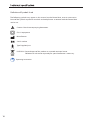
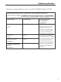
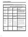
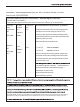
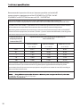
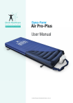
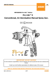
Contents
Important Notice
Before operating this medical equipment, it is
important to read this manual and understand
the operating instructions and safety
precautions. Failure to do so could result in
patient injury and/or damage to the product.
If you have any questions, please see contact
information on cover.
Safety Precautions.......................................... 3
Product Overview............................................. 4
Installation.......................................................... 5
Unpacking & Inspection.................................. 5
Installation Guide.............................. see cover
Operation................................................................ 6
Control Unit Panel............................................ 6
Alarm Functions................................................ 7
Mattress Function............................................. 8
Removal & Transport Function...................... 9
Troubleshooting.............................................10
Cleaning................................................................12
Maintenance.......................................................14
Warranty Information................................15
Technical Specifications.................. see cover
1
2
SAFETY PRECAUTIONS
In General
Control Unit
Do not use this equipment in the
presence of flammable anesthetics.
Explosions could result.
The control unit is tested and approved
according to ISO-EN 60601-1 rev.2 & EMC
Bed frames used with the systems can
vary greatly depending on the specific health
care setting (i.e. hospitals, nursing homes,
home care, etc). It is the responsibility of the
caregiver to take the necessary precautions
to ensure the safety of the patient. This
includes, but is not limited to, the appropriate
use of side rails to prevent falls and/or patient
entrapment.
Minimize articles between the system
surface and patient, and secure bed sheets
loosely so as not to affect the alternating cell
movement.
The manufacturer does not require such
preventive inspections by other persons.
The user must check that the equipment
functions safely and see that it is in proper
working condition before being used.
No special skills or training of the operator is
required. there is no restriction on the location
or the environment.
Significant risks of reciprocal interference may
be posed by the presence of the system during
specific investigations or treatments. Potential
electromagnetic or other interference bewteen the
system and other device may occur, if interference
is suspected, move equipiment from sensitive
devices or contact the manufacturer.
Preventive inspection and calibration is not
required.
Do not modify this equipment without
authorization of the manufacturer.
Manufacturer will provide circuit diagrams,
component part lists, descriptions to assist to
service personnel in parts repair.
The mattress is treated as the applied part.
Unplug the control unit from the mains
power supply to disconnect the power.
Only plug into a grounded power
receptacle and use the power cord supplied
with the system.
Exposure of the electronic Control Unit to
any liquid while it is plugged in could result in
a severe electrical hazard.
Only use fuses that have the same
specified rating. Using fuses with higher
ratings could result in damage and/or injury.
(See Technical Specifications on cover).
The electronic Control Unit is a precision
electronic product. Use care when handling
or transporting. Dropping or other sudden
impacts may result in damage to the unit.
Do not open the Control Unit – risk of
electrical shock. Do not attempt to repair or
service the Control Unit. Repairs and service
should be conducted by an authorised local
distributor. (See contact information on cover).
If the Control Unit is not functioning properly,
or has been damaged, unplug the unit and
take it out of service immediately. (See contact
information on cover for repair and service
information).
Do not place any objects or items, such
as blankets, on or over the Control Unit.
The power cord to the Control Unit should
be positioned to avoid a tripping hazard and/
or damage to the cord.
It is recommended to place the cord under
the bed frame and attach it to an electrical
outlet by the head of the bed.
Do not position the system so that it is difficult
to operate the disconnection device.
3
Product Overview
Alternating Mattress System (see cover)
Dyna-Form Air Pro-Plus is an alternating Mattress
Replacement system providing pressure
application and release to patients with, or
vulnerable to, pressure ulcers. It is designed to
replace an existing mattress and can be used on
Control Unit
The Control Unit provides the air supply to the
Mattress.
•
It is controlled via a touch panel with
integrated digital display. The Alarm sounds
both standard and profiling bed frames.
when pressure fails or power is interrupted.
Mattress
Alarm Mute silence the alarm for maximum
This system includes a static head cell(s) to
of 20 minutes – the alarm resumes if cause
provide static “pillow” support for optimum user
of failure is not resolved. The Alarm will
comfort, while air pressure in the other cells
sound for up to two hours following an
is alternated over a 10 -12 minute cycle. This
interruption to power.
provides regular periods of pressure reduction
•The Control Unit includes a back up
to aid blood and lymphatic flow to vulnerable
power battery for the alarm. This battery is
tissue.
continuously re-charged will last the life time
of the product.
•
Buttons on the control panel adjust the three
comfort level settings.
•The Alarm LED indictor and Alarm Mute
completes the profile.
The visible and audible alarm functions has a
number of indications depending on the cause
of the failure.
The mains supply to the Control Unit can
be easily disconnected and is designed to
detach if tugged too firmly - protecting the
internal wiring of the unit. Should this occur,
the alternation sequence is suspended and the
Mattress cells remain inflated and/or deflated
based on the current cycle. The Power Down
Alarm will sound. (See picture on inside cover).
4
Installation
Unpacking & Inspection (see cover)
It is recommended that all packing materials
and instructions be kept in the carry bag
provided in the event the product has to be
shipped to Direct Healthcare or an authorised
local Direct Healthcare distributor. Please see
contact information on cover.
Carefully remove the Control Unit, Mattress
Replacement and accessories from the shipping
cartons. Inspect all items for any damage
that may have occurred during shipping. Any
damage or missing components should be
reported to Direct Healthcare or an authorised
local Direct Healthcare distributor as soon as
possible. Please see contact information on
cover.
5
Operation
Control Unit Panel (see inside cover)
A Power Button
Turns system power on and off by pressing the
Power button for at least two seconds.
B Alarm LED *A,B & C
One of *these red light flashes, and an audible
alarm sounds, to alert when Control Unit or
Mattress Replacement pressure fails. The alarm
the previous pressure setting for patient safety.
Static Mode will automatically revert to
Alternation Mode after one hour for patient
safety.
F Static Function Button
Press to facilitate static mode for clinical
has three different signals to indicate the cause
procedure / patient transfer purposes. After
of the failure (see over)
20 minutes, the system automatically reverts
The audible alarm also sounds when power is
switched off – press Alarm Mute to silence.
C Alarm Mute Button
Silences the audible alarm (on / off ). Audible
alarm will resume after 20 minutes if cause of
failure not resolved.
D Pressure Buttons (Soft, Medium & Firm)
Press buttons to increase or decrease pressure
setting. The Soft Medium & Firm settings
allow comfort to the user, without clinical
compromise. The green LEDs illuminate
to indicate which of the three settings is
operational.
E Dynamic Function Button
Press Dynamic Mode for alternative cells
cyclically inflating and deflating.
Static Mode will automatically revert to
Alternation Mode after one hour for patient
safety.
Upon power up, the system automatically
6
reverts back to the dynamic mode operating at
back to the previous pressure setting for patient
safety.
Press Static Mode for all cells to be fully inflated
with no dynamic alternation.
Static Mode will automatically revert to
Alternation Mode after one hour for patient
safety.
G Control Unit Lock / Unlock Button
Press for at least two seconds to lock the
Control Unit settings – a beep sounds and the
amber LED illuminates to indicate system is
locked. When locked, only the Alarm Mute and
Lock / Unlock buttons remain operational.
Press again for at least two seconds to unlock
(beep sounds and amber LED turns off ).
The Control Unit will automatically unlock
in the event of a power failure.
OPERATION
Alarm Function
The red Alarm LED (A,B or C) flashes, and an
audible alert sounds, to indicate the control
unit or mattress pressure has failed. The LED will
remain illuminated until appropriate pressure is
restored. The audible alarm can be silenced by
pressing the Alarm Mute button.
The system has three different alarm signals,
identified by illumination sequences.
A
B
C
The signals and corresponding Pressure Setting
LED displays are illustrated below.
Display
Alarm Signal
High pressure
The system cannot reach the set pressure within 8
minutes. The system pressure is to high.
Low pressure
The system cannot reach the set pressure within 8
minutes. The system pressure is to low.
Mains Failure
Power unit has no power feed.
A B C
A B C
A B C
If alarm activates and the system fails to inflate or loses pressure, refer to Troubleshooting on following
pages.
7
Operation
Mattress Function
Establishing Pressure (supine patient)
With the patient lying supine (on their back,
Establishing Pressure (inclined
patient)
face upwards), use the Pressure arrows to
When moving the patient to a sitting or more
cycle through the eight available pressure
upright position, pressure may need to be
settings.
increased to a medium or firm setting in order to
Based on patient weight and comfort
provide added support and to avoid ‘bottoming
requirements, establish the best setting for
out’.
effective alternation, support and comfort.
It is important to return to the original
pressure setting when the patient returns to
the supine position.
Before changing or lowering the pressure,
ensure the system is working effectively by
performing a ‘bottoming out’ test:
Bottoming Out Test
Wait a minimum of 12 minutes between
pressure adjustment and patient assessment,
as it may take a cycle for the system to adjust.
When altering the pressure setting, ensure the
patient is not ‘bottoming out’ (insufficiently
supported by the air cells and therefore coming
in contact with bed base).
1. Ensure system is in alternation mode but is
not undergoing an alternation.
2. With the patient lying in a supine position,
CPR Function
Rapid deflation of the Mattress may be required
for emergency treatment or to decommission the
system. Firmly pull the Rapid Release /CPR Handle
from the side of the Control unit to rapidly deflate the
entire system.
unzip top cover just past sacral (bottom)
To re-inflate the system after the Rapid Release
region.
/CPR Handle has been removed replace as
3. Slide your hand along a deflated cell under
such, ensuring all sealing connectors are firmly
the patients sacral area (bottom). The inner
attached and restart the Control Unit. Wait for the
static cell will remain inflated but your hand
Mattress system to gain optimal pressure.
should slide easily between patient and
Perform a Bottoming Out test after inflating the
base.
mattress following rapid deflation.
4. If a hand can pass under patient then the
patient is adequately suspended and pressure can be lowered.
5. Repeat Bottoming Out test after pressure
has been lowered.
Mattress replacement / Overlay
Function
The mattress body of the Air Pro-Plus can be used
as a mattress replacement system or as an overlay
system. The standard delivery status is as a
In the event of a system malfunction, the alarm
mattress replacement system. To use the Air Pro-Plus
will activate and pressure LEDs will flash.
as an overlay system, zip off the bottom part of
the mattress body which holds the foam base.
Once the bottom part is removed, the mattress
body can be placed on a standard hospital
mattress before patient use.
8
Operation
Transport Function
System Removal
1.Before patient transport, switch modes
1. Turn off the Control Unit by pressing the
from alternating to static and wait for 10
Power button for at least two seconds and
-12 minutes for cells to inflate to maximum
unplug the power cable.
pressure.
2.Turn off the Control Unit.
3.Remove the mattress connection from the
2.Remove the Rapid Release Handle from the
Control Unit.
3. Place Control Unit and power cable on top
Control Unit. Allow air to escape for a few
of the Mattress and detach Mattress from
seconds before sealing with the attached
the bed frame.
transport cap, see picture on cover. This
will soften the Mattress surface for pressure
relief and comfort. Air can be seal in the
system for 30 hours as a transport feature.
If the patient is responsive, check comfort
level based on current pressure and adjust
4.Once air has been released from all cells,
roll up the Mattress and return all items to
Carry Bag for safe keeping.
Prior to re-starting the system, ensure the
Rapid Release Handle is firmly connected to the
Control Unit.
accordingly.
Always perform a ‘bottoming out’
test (see page 8) to ensure the patient is
adequately supported and not touching bed
base.
9
TROUBLESHOOTING
Alarm/Fault
Cause
Solution
Control Unit does not
The Control
1. Check the Control Unit is connected to mains power
operate; no display
Unit may not be
lights illuminate
attached to a
power source or
a fuse may need
replacing
outlet with the correct voltage.
2. Check the Control Unit is switched on. Switch off and
unplug the unit before restarting.
3. Check the mains plug fuse (3 AMP) then check both
Control Unit fuses (1 AMP) – fuses can be released
using a screwdriver to push and turn.
Do not try to open the Control Unit. Opening the
unit could cause personal injury or equipment damage.
Ensure the replacement of fuses is carried out
accordance with local legislation.
Alarm LED
C
Mains failure /
Other
(see above plus>)
+ audible alarm
1. Reset the alarm -turn off power and press the alarm
mute button.
2. Check the handle is intact, ensuring all four sealing
connectors are firmly fitted to the control unit and
the air hoses. Check the CPR tag is attached and all
sealing connectors are firmly secure.
3. Check all air hoses along the inside of the mattress
-each should be firmly connected. Check each air
cell is securely attached to its connecting air pipe.
4. Check all cells, pipes and hoses for any air leakage.
5. Switch on power.
A B C
Alarm LED
B
+ audible alarm
A B C
10
Pressure too low
1. Reset the alarm -turn off power and press the alarm
mute button.
2. Check the handle is intact, ensuring all four sealing
connectors are firmly fitted to the control unit and
the air hoses. Check the CPR tag is attached and all
sealing connectors are firmly secure.
3. Check all air hoses along the inside of the mattress
-each should be firmly connected. Check each air
cell is securely attached to its connecting air pipe.
4. Check all cells, pipes and hoses for any air leakage.
5. Check that the air filter cover is correctly secured
and the air filter is clean.
6. Switch on power.
TROUBLESHOOTING
Alarm/Fault
Cause
Alarm LED
Pressure too high
A
+ audible alarm
Solution
1. Reset the alarm -turn off power and press the alarm
mute button.
2. Disconnect the air hoses to reduce pressurereconnect when pressure has decreased.
3. Check for twists in the air hoses between Mattress
and Control Unit.
4. Switch on power.
A B C
Other checks to consider as below:
Alarm LED
Alternating
Any
Mode Failure
+ audible alarm
Alarm LED
(no alternation)
1. Reset the alarm – turn off Power and press the
Alarm Mute button.
2. Disconnect the air hoses to reduce pressure –
reconnect when pressure has decreased.
Power down
1. Press the Alarm Mute button to silence the
audible alarm.
Any
2. Check the power cable is firmly plugged into the
+ audible alarm
mains outlet and the Control Unit; and check the
mains power is switched on.
3. Check the Control Unit fuse (1 AMP) – fuses can
be released using a screwdriver to push and turn.
Patient is sinking
The pressure may
or “bottoming out”
be set too low
whilst lying flat on the
for the patient’s
Mattress Replacement
weight
1. Increase the pressure setting by pressing up the
Pressure arrow.
2. To check effective system performance, conduct a
“bottoming out” test as described on page 8.
If the problem is not resolved, please contact
Direct Healthcare or an authorised local distributor.
See contact information on cover.
11
Cleaning
Before the cleaning and disinfection procedure,
please use hygienic hand disinfection with an
alcoholic skin disinfectant.
To protect clothing, use plastic apron, face
mask and gloves.
Infection Control and routine cleaning must
Mattress Base
Wipe down the outside shell with authorised
cleaning and disinfection solutions, ensuring
that all surfaces come in contact with the
disinfectant. Rinse off well with a clean damp
cloth and air dry. Should Air Cells require
disinfecting, disconnect
be carried out in accordance with your local
Air Cells from the base by unfastening the press
Infection Control Policy. It is suggested that
studs at each end and disconnecting air pipes
all disinfection be done with a high grade
from main air hoses before sliding each cell
disinfectant in accordance with manufacturer’s
out from the cell straps. Swab with authorised
instructions.
cleaning and disinfection solutions. Dry
thoroughly with a soft cloth before refastening.
Use authorised cleaning and disinfection
solutions only!
The working table and the system must
be cleaned and disinfected.
Concentration and exposure time of the
solutions must be noted!
The top cover seams are sealed to
prevent moisture ingress and bacterial
growth in the seam stitching.
Do not use high temperature autoclave,
or use Phenolic based products for cleaning.
It is recommended the system is cleaned
between patients and approximately every
two weeks if in constant use.
Refer to the cleaning and disinfection
information for the Air Pro-Plus system for
additional guidance.
In case of questions in hygiene please
contact an authorised local Direct Healthcare
distributor.
12
Do not machine wash or dry the Air Cells
or Mattress base.
Do not disassemble the Mattress unless
cleaning is required. If cleaning or disinfecting
is required, do not disconnect the pipes from
individual Air Cells.
CLEANING
Top Cover
Handle
Refer to the top cover wash tag for
cleaning instructions.
The exterior of the Handle can be periodically
wiped using a cloth a dampened with authorised
cleaning and disinfection solutions.
If there are visible signs of body fluids and or
substances present, the top cover should be
washed. Top covers can be machine washed
(up to 95ºC) using authorised cleaning and
disinfection solutions.
To establish the amount of disinfectant to use,
determine the amount of water in the washer
and then follow the manufacturers’ instructions
for dilution.
Soak the top cover in the disinfectant during
the wash cycle. Rinse well in clean water and
dry thoroughly before use.
Do not dry the top cover using too
high a heat cycle (see Dartex technical
recommendations - up to 95ºC ). Air dry if
possible or select a n appropriate heat dry cycle
within limits as above. If there are no visible
signs of body fluids and or substances on the
top cover, the top cover should be sanitized and
rinsed with fresh water accordingly.
Control Unit
Ensure the Control Unit is disconnected
from the mains electricity supply before
cleaning.
Do not spray disinfectant directly on
to the Control Unit, or immerse the Control
Unit in any type of liquid. This could result in
a severe electrical hazard as this equipment
has no protection against ingress of water.
This equipment is not suitable for use
in the presence of a flammable anesthetic
mixture with air or with oxygen or nitrous
oxide.
Wipe down Control Unit with warm water
containing detergent (or authorised cleaning
and disinfection solution) and dry thoroughly
before use.
If there are no visible signs of body fluids and
or substances on the top cover, the top cover
should be sanitized.
1. Apply an intermediate level authorised
.. cleaning and disinfection solution to the
top cover upper surface either by spraying
In case of notifiable diseases clean and
disinfect systems following eventually special
procedures revised and published by the
local health care authorities. The transport
should take place in special plastic bags only.
or by hand application.
2. Ensure the surface is completely covered
with the disinfectant and remains in
contact with the surface according to
manufacturer’s instructions.
3. Remove disinfectant and rinse thoroughly.
4. Allow to air dry before use.
13
Maintenance
Air Filter Replacement
Fuse Replacement
1.Switch off the power supply to the
1.Switch off the power supply to the
Control Unit.
2.Disconnect the power lead and air hoses.
3.Place the Control Unit on a flat surface with
back panel uppermost (place soft cloth
under unit to prevent scratches).
4.Carefully remove air filter cover, remove and
discard the filter material and fit new filter
(there may be a small locking screw – use a
small Phillips Head screwdriver to remove).
5.Refit the air filter cover to the Control Unit.
2.Remove the power cord from the electrical
socket on the side of the base of the
Control Unit.
3.Insert a small Flat Head screwdriver into
the groove and turn anti-clockwise
(quarter turn).
4.Remove the “blown” fuse from the fuse
holder clip and discard.
5.Insert a new fuse into the plug. Push against
The Control Unit is now ready for
the force of the spring and turn clockwise
re-connection.
with the screwdriver (quarter turn).
Good filter maintenance is critical to
maintain your system in optimal operating
condition. Failure to keep the filters clean will
result in system downtime and increase repair
costs. It is recommended that the air filter
be replaced annually. Replacement air filters
are available from an authorised local Direct
Healthcare distributor. Please see contact
information on cover.
14
Control Unit.
Ensure the replacement of fuses
is carried out accordance with local
legislation.
Warranty Information
This product is produced to perform in
accordance with established specifications,
starting from the date the product is shipped.
For warranty period see Technical Specification
on cover.
During the warranty period repairs and
replacement will be made on products that are
not performing in accordance with established
specifications, unless the problem/failure is
due to:
•
customer damage, negligence and/or
misuse.
•
unauthorised repairs.
Items not covered under warranty include,
but are not limited to, stains, punctures, cuts,
damages to electrical cords, rips or tears,
dents and/or lost/missing parts.
Neither the company(See contact information
on cover), its distributors, officers, directors,
employees or agents shall be liable for
consequential or other damages, including but
no limited to personal injury, loss, or any other
expense, directly or indirectly arising from the
use of its products. The sole remedy for breach
of the limited warranty granted herein shall be
repair or replacement of the products.
If you have any questions see contact
information on cover.
15
Definition of Symbols Used
The following symbols may appear in this manual, on the Control Unit, or on its accessories.
Some of the symbols represent standards and compliances associated with the Control Unit
and its use.
Caution: Consult accompanying documents
Class II equipment
Manufacturer
Serial number
Type B applied part
DISPOSAL: Do not dispose of this product as unsorted municipal waste.
Collection of such waste separately for special treatment is necessary.
Operating Instruction.
16
Declaration – electromagnetic emissions - for all ME EQUIPMENT and ME SYSTEMS
Guidance and manufacture’s declaration – electromagnetic emission
The MAT/PRO-PLUS/PUMP is
The customer or the user of the system should ensure that it is used in such an environment.
Emission test
Compliance
Electromagnetic
environment
– guidance
RF emissions
Group 1
The system uses RF energy
only for its internal function.
CISPR 11
Therefore, its RF emissions
are very low and are not likely
to cause any interference in
nearby electronic equipment.
RF emission
Class B
in all establishments, including
CISPR 11
Harmonic emissions
The system is suitable for use
Class A
IEC 61000-3-2
domestic establishments and
those directly connected to
the public low-voltage power
Complies
supply network that supplies
emissions
buildings used for domestic
IEC 61000-3-3
purposes.
17
Declaration – electromagnetic immunity
Guidance and manufacture’s declaration – electromagnetic immunity
The MAT/PRO-PLUS/PUMP is
The customer or the user of the system should ensure that it is used in such an environment.
Immunity test
IEC 60601
test level
Compliance
level
Electromagnetic
environment
– guidance
Electrostatic
±6 kV contact
±6 kV contact
Floors should be wood, concrete
discharge (ESD)
±8 kV air
±8 kV air
IEC 61000-4-2
with synthetic material, the relative
humidity should be at least 30%.
Electrical fast
±2 kV for power
±2kV for power
Mains power quality should be that
transient/burst
supply lines
supply lines
of a typical commercial or hospital
environment.
IEC 61000-4-4
Surge IEC 61000-
± 1 kV line(s) to
4-5
line(s)
Mains power quality should be that
mode
of a typical commercial or hospital
environment.
Voltage dips,
<5% U T (>95% dip
<5% U T (>95%
Mains power quality should be that
short interruptions in U T ) for 0.5 cycle
dip in U T ) for 0.5
of a typical commercial or hospital
and voltage
40% U T (60% dip
cycle
environment. If the user of the
in U T ) for 5 cycles
40% U T (60% dip
Span system requires continued
70% U T (30%
in U T ) for 5 cycles
dip in UT) for 25
70% U T (30% dip
cycles
in U T ) for 25 cycles
<5% U T (>95%
<5% U T (>95%
dip in U T ) for 5 sec
dip in U T ) for 5 sec
3A/m
3A/m
variations on
power supply
input lines
EC 61000-4-11
Power frequency
operation during power mains
interruptions, it is recommended
that the system be powered from
an uninterruptible power supply or
a battery.
Power frequency magnetic
(50Hz) magnetic
characteristic of a typical location
IEC 61000-4-8
NOTE
18
U T is the a.c. mains voltage prior to application of the test level.
in a typical commercial or hospital
environment.
Declaration – electromagnetic immunity – for ME EQUIPMENT and ME SYSTEMS
that are not LIFE-SUPPORTING
Guidance and manufacture’s declaration – electromagnetic immunity
The MAT/PRO-PLUS/PUMP is
The customer or the user of the system should ensure that it is used in such an environment.
Immunity
test
IEC 60601
test level
Compliance
level
Electromagnetic environment - guidance
Conducted
3 V rms
3 V rms
Portable and mobile RF communications equipment
RF
150 kHz to
IEC 61000-
80 MHz
should be used no closer to any part of the CT515,
including cables, than the recommended separation
distance calculated from the equation applicable to the
4-6
frequency of the transmitter
Recommended separation distance
Radiated
RF
IEC 610004-3
d = 1.167√P
3 V/m
80 MHz to
2.5 GHz
3 V/m
d = 1.167√P
80 MHz to 800 MHz
d = 2.333√P
800 MHz to 2.5 GHz
Where P is the maximum output power rating of the
transmitter in watts (W) according to the transmitter
manufacturer and d is the recommended separation
distance in meters (m).
by an electromagnetic site survey, a should be less than
the compliance level in each frequency range.
b
Interference may occur in the
vicinity of equipment marked
with the following symbol:
NOTE 1 At 80 MHz and 800 MHz, the higher frequency range applies.
mobile radios, amateur radio, AM and FM radio broadcast and TV broadcast cannot be predicted theoretically with
the applicable RF compliance level above, the system should be observed to verify normal operation. If abnormal
performance is observed, additional measures may be necessary, such as reorienting or relocating the system.
19
Recommended separation distances between portable and mobile RF
communications equipment and the EQUIPMENT or SYSTEM - for ME
EQUIPMENT or ME SYSTEM that are not LIFE - SUPPORTING
Recommended separation distances between portable and mobile RF
communications equipment and the MAT/PRO-PLUS/PUMP Alternating Control Unit
The MAT/PRO-PLUS/PUMP is intended for use in an electromagnetic environment in which radiated
RF disturbances are controlled. The customer or the user of the system can help prevent
electromagnetic interference by maintaining a minimum distance between portable and mobile RF
communications equipment (transmitters) and the system as recommended below, according to the
maximum output power of the communications equipment.
Rated maximum
output power of
transmitter (W)
Separation distance according to frequency of
transmitter (m)
150 KHz to 80 MHz
80 MHz to 800 MHz
800 MHz to 2.5 GHz
d = 1.167√P
d = 1.167√P
d = 2.333√P
0.01
0.117
0.117
0.233
0.1
0.369
0.369
0.738
1
1.167
1.167
2.333
10
3.689
3.689
7.379
100
11.667
11.667
23.333
For transmitters rated at a maximum output power not listed above, the recommended separation
distance d in meters (m) can be estimated using the equation applicable to the frequency of the
transmitter, where P is the maximum output power rating of the transmitter in watts (W) according to
the transmitter manufacturer.
NOTE 1 At 80 MHz and 800 MHz, the separation distance for the higher frequency range applies.
objects and people.
20