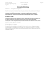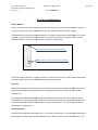
1
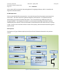
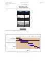
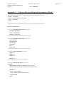
FINAL DESIGN REPORT
Dodge This!
DODGERS:
Cristobal Rivero
Derek Fairbanks
4/21/2009
Abstract:
Our project is to develop an automatic dodge ball game. It consists of an infrared video camera,
computer, ball launcher, and various gears, motors, and lights. The idea of the game is simple. The
computer targets a player using the video camera, LEDs, and tracking software. Data is transferred to a
microcontroller-operated system to aim and fire a ball at the player.
The object of the game is for the player to test his/her reflexes by dodging multiple balls. The launching
and tracking mechanism can be placed at a table about ten feet away from the player. The player will be
wearing safety lenses with an LED light attachment, used for head-tracking.
University of Florida
Electrical & Computer Engineering
Page 2/13
EEL 4924—Spring 2009
20-Apr-09
Team: DODGERS
TABLE OF CONTENTS
Product Features & Objectives........................................................................................................................ 3
Analysis of Competitive Products.................................................................................................................... 3
Concept & Technology .................................................................................................................................... 4
Project Architecture ........................................................................................................................................ 5
Separation of Work ......................................................................................................................................... 7
User’s Manual.................................................................................................................................................. 7
Bill of Materials ............................................................................................................................................... 8
Gantt Chart ...................................................................................................................................................... 8
Appendix A – Code used for tracking and servomotor (Basic)........................................................................ 9
Appendix B – Code used for menu, launcher, and solenoid (Basic)................................................................ 11
TABLE OF FIGURES
Figure 1 - Wii remote used for tracking ........................................................................................................ 5
Figure 2 - Flow of information chart ............................................................................................................. 6
Figure 3 - Gantt chart for Dodge This! project .............................................................................................. 8
University of Florida
Electrical & Computer Engineering
Page 3/13
EEL 4924—Spring 2009
20-Apr-09
Team: DODGERS
Product Features & Objectives
The Dodge This! robot finds application in the gaming domain and object tracking domain. It has to find
the object, aim at it, and then hit it with the ball at a desired speed. The aim of the robot is to be
entertaining for the audience, and also engaging and challenging for the user
Usually, dodge ball is played with opposite teams trying to hit the other. For the Dodge This! robot,
there is only one player and he/she is only dodging the ball, never throwing. There is nothing quite like
the Dodge This! robot. There are tracking devices and turrets in the world. There are also ball launchers
and potato launchers. However, this machine combines the ability to track and launch to create a
unique and fun experience.
Analysis of Competitive Products
Since there are no tracking ping pong ball launchers that use Wii remote designs that we could find, this
will be a comparison to the designs that gave us ideas. Note that our design is more simple and
inexpensive as these commercial products. Much of the design of this project was formed from ideas
provided by the products listed below.
Tennis Ball Launcher:
The launching system (two motors spinning wheels in opposite directions) was inspired by the tennis
ball launcher. These systems start at around $300.
Paintball Turret:
Further inspiration came from automatic paintball turrets that are becoming popular online. Most used
motion sensing, with more sophisticated software (these custom software applications run at $150 on
their own).
University of Florida
Electrical & Computer Engineering
Page 4/13
EEL 4924—Spring 2009
20-Apr-09
Team: DODGERS
Concept & Technology
Wii Remote vs. Motion/Color Sensing Camera:
The Wii remote was not the initial camera for this project. Motion or color sensing was the preliminary
mode of tracking the player. However, after extensive research and peer recommendations, the Wii
remote was chosen for tracking infrared light. This decision was based upon cost and ease of
implementation. It is assumed that a good percentage of households now have the Wii console.
PIC 18F1320 vs. ATMEL:
An ATMEL processor was initially chosen for this project. However, we came to the conclusion that the
PIC 18F1320 would suit this project better because we had previous experience with the PIC
microcontroller and the ATMEL had a learning curve we did not have time to devote to. Overall, the PIC
provided all that was required for this project.
DC Brush Motors vs. Air Pressure:
Two types of launching methods were thought of: DC motors and air pressure. Air pressure required
several moving parts including plus pressure sealings. Also, a small pressurizer was out of our budget.
Upon learning that tennis ball launchers use motor powered wheels spinning in opposite directions, this
method was decided on.
University of Florida
Electrical & Computer Engineering
Page 5/13
EEL 4924—Spring 2009
20-Apr-09
Team: DODGERS
Project Architecture
The Wii Remote:
Initially, a video camera was to be used along with face tracking or motion sensing software. However,
time and financial constraints required the pursuit of a different tracking method: infrared.
The Nintendo Wii remote was chosen because of its versat
versatility
ility and sensitive infrared camera. As shown
in Figure 1 below, the infrared camera is at the front end of the remote. The Buttons 1 and 2 can be
used to prepare the remote to be paired with a computer via Bluetooth.
Infrared Camera: Used to track the player
Buttons 1&2: Used to pair with the computer
Figure 1 - Wii remote used for tracking
Once paired with a computer, a program written in Visual C# (Johnny Lee) is used to enable information
from the remote to be transferred and manipulated by the computer.
Visual C#:
The Visual C# program used in this project was initially designed only to
o connect the Wii remote to the
computer and output information to the user (coordinates of IR camera, battery life, LEDs, button
pressing, etc.).
This program has been manipulated to open a communications port for the serial connection to the
microprocessor. The program then converts the xx-coordinate
coordinate of a single infrared light captured by the
camera into 8-bit values (0=left-most
most position, FF=right
FF=right-most
most position). This byte is then transferred
serially to the microprocessor.
Launching Device:
The actual launching setup consistss of a PVC ‘T’ cap fed by a vertical tube. A solenoid loads and shoots a
ball through two wheels spinning in opposite directions, which are driven by two 18V DC motors. This
University of Florida
Electrical & Computer Engineering
Page 6/13
EEL 4924—Spring 2009
20-Apr-09
Team: DODGERS
entire system will be mounted on the panning device for targeting the player, which is rotated by the
large servo mentioned earlier.
PIC Microprocessor:
There are two PIC 18F1320 microcontrollers. One reads the input from the computer and controls the
servo motor. The other controls the speed and frequency of the launcher. The speed of the ball is
determined by the rotational speed of the wheels. This is controlled using a PWM signal that runs
through a MOSFET. The frequency of the balls is a constant pulse controlling a relay, which activates
and deactivates the solenoid. These microcontrollers communicate with each other if there is no player
in sight. The first scans scan back on forth to search for the player, while the second cancels firing until a
player is found.
Entire System:
The flowchart in Figure 2 below explains pictorially the flow of information discussed in the previous
sections.
Wiimote:
Determines player’s position through IR
sensing
•
•
•
Laptop Computer:
Program takes Wiimote input and
changes position into a serial 8-bit
number
Servomotor:
Turns launcher left and right
PIC for Tracker:
Serial input into built-in UART.
Servomotor output. The position
is determined from serial input
Tells other PIC if player is in sight
LCD screen:
Outputs messages and menus
Pushbuttons:
Input for launcher speed
•
•
Solenoid:
Pushes ball through motors. A MOSFET
and Relay are used to control solenoid.
•
•
PIC for launcher:
LCD output for User interface
Launcher speed by
pushbuttons
Motor PWM speed control
Solenoid control (stops if
player not in sight)
Figure 2 - Flow of information chart
18V supply
Motors
University of Florida
Electrical & Computer Engineering
Page 7/13
EEL 4924—Spring 2009
20-Apr-09
Team: DODGERS
Separation of Work
Cristobal Rivero: Launching System
•
•
•
Built launching platform
Prepared launching system, including choosing DC motors, wheels, and a solenoid
Developed Visual Basic code to control DC motors and solenoid, with user interface
Derek Fairbanks: Tracking System
•
•
•
Paired Wii remote with computer
Edited C# code to output Wii remote data serially to PIC
Developed Visual Basic code to input serial data and control servo
User’s Manual
Step 1: Pair the Wii Remote
Since the Wii remote communicates via Bluetooth, the computer to pair with must also have Bluetooth
connectivity. Press the ‘A’ and ‘B’ buttons simultaneously. Blinking LEDs means that the pairing process
has begun. Run a search with the Bluetooth software and choose the item labeled Nintendo ##-##.
Then, check the box which chooses not to use a passkey. The software should install the Wii remote as
a peripheral. During this process, the two buttons may need to be pressed again.
Step 2: Plug in the USB
Plug a USB cable in both the computer and the circuit board. This must be done before the software is
run, or the computer will not send any information.
Step 3: Open Software
Double-click on the provided software. If the information box opens, the software package is working
fine.
Step 3: Start Motors / LED Glasses
Flip the main switch and follow the LCD screen to choose the desired motor speed. Flip the switch on
the LED Glasses. Once these steps are followed, the system will be tracking the player and will
automatically begin launching ping pong balls.
University of Florida
Electrical & Computer Engineering
Page 8/13
EEL 4924—Spring 2009
20-Apr-09
Team: DODGERS
Bill of Materials
The cost and components for Dodge This! system is shown in Table 1.
ITEM
PRICE
Launcher Platform
Servo Motor
Wii Remote
Solenoid
DC Motors
LEDs & Buttons
LCD Screen
PIC Processor
Relay
IR Glasses
TOTAL
Awesome Project
$10.00
$40.00
$40.00
$3.00
$8.00
$10.00
$10.00
$5.00
$5.00
$20.00
$151.00
Priceless!
Gantt Chart
The Gantt chart for the Dodge This!
is! project is shown in Figure 3.
0
1
2
3
4
5
6
7
8
9
Introduction (team)
Research/project proposal (team)
Build targeting system (Derek)
Build launch and pan system (Cris)
Incorporate code to launch ball…
Build player interface (Team)
Debugging
Demo and final presentations(team)
Planned
Figure 3 - Gantt chart for Dodge This! project
10 11 12 13 14 15 16
University of Florida
Electrical & Computer Engineering
Page 9/13
EEL 4924—Spring 2009
Team: DODGERS
Appendix A – Code used for tracking and servomotor (Basic)
'****************************************************************
'* Name : Serial.BAS
*
'* Author : Derek Fairbanks / Cris Rivero
*
'* Date : 2/11/2009
*
*
'* Notes :
*
'*
:
*
'****************************************************************
INCLUDE "modedefs.bas"
'**********REGISTER DEFINITIONS**********
OSCCON = %01101011
RCSTA = %10010000
ADCON1 = %11111111
'****************************************
'**********VARIABLE DEFINITIONS**********
serial VAR BYTE
servo VAR BYTE
diff VAR byte
dir var byte
dir = 1
servo = 150
'****************************************
'**********I/O DEFINITIONS**********
TRISA.4 = 1
TRISB.5 = 0
TRISB.6 = 0
PORTB.6 = 0
'***********************************
'**********READ SERIAL INPUT**********
SerialRead:
SERIN PORTA.4, T9600, 10, NoSeeEms, ["0","Z"], serial
'Will wait 10ms for input, then continue to SeroOut if none
PORTB.6 = 1
if servo > serial + 20 then
servo = servo - ((servo - serial) / 65 + 1)
goto ServoOut
endif
20-Apr-09
University of Florida
Electrical & Computer Engineering
Page 10/13
EEL 4924—Spring 2009
Team: DODGERS
if servo < serial - 20 then
servo = servo + ((serial - servo) / 65 + 1)
goto ServoOut
endif
'*************************************
'**********OUTPUT TO SERVO**********
ServoOut:
PORTB.5 = 0
pulsout PORTB.5, servo
PAUSE 10 'Final delay to make a 20ms pulse waveform for servo
GOTO SerialRead
'***********************************
NoSeeEms:
PORTB.6 = 0
servo = servo + dir
if servo > 170 then
dir = -1
endif
if servo < 130 then
dir = 1
endif
goto ServoOut
20-Apr-09
University of Florida
Electrical & Computer Engineering
Page 11/13
EEL 4924—Spring 2009
Team: DODGERS
Appendix B – Code used for menu, launcher, and solenoid
(Basic)
'****************************************************************
'* Name : SpeedFreq.BAS
*
'* Author : Cris Rivero / Derek Fairbanks
*
'* Date : 03/24/2009
*
*
'* Notes :
*
'*
:
*
'****************************************************************
osccon = %01101011
adcon1 = %11111111 'set digital pins
DEFINE CCP1_REG PORTB
DEFINE CCP1_BIT 2
' Set LCD Enable bit
DEFINE LCD_EBIT 2
'**********I/O DEFINITIONS**********
TRISB.0 = 1 'dont shoot!
TRISB.1 = 1
TRISB.2 = 0
TRISB.4 = 1
TRISB.5 = 1
TRISB.6 = 1
TRISB.7 = 1
TRISA.6 = 0 'used for servo pulse out
TRISB.3 = 0
'***********************************
'**********VARIABLE DEFINITIONS**********
n var BYTE
servo VAR BYTE
diff VAR BYTE
Freq var byte
20-Apr-09
University of Florida
Electrical & Computer Engineering
Page 12/13
EEL 4924—Spring 2009
Team: DODGERS
countOff var word
DutyCycle var byte
PWMfreq var word
Button1 var PORTB.4
Button2 var PORTB.5
Button3 var PORTB.6
Button4 var PORTB.7
Button5 var PORTB.1 'what number?
Solenoid var PORTA.6
DontShoot VAR portb.0 'naming
countOff = 0
Solenoid = 0
n = 100
PWMfreq = 100
servo = 250
diff = 200
DutyCycle = 0
HPWM 1,DutyCycle,PWMfreq
'****************************************
'*********DISPLAY SPEED OPTIONS**********
SpeedDisplay:
LCDOUT $FE, 1
LCDOUT $FE, $80
LCDOUT "ENTER SPEED:"
LCDOUT $FE, $C0
LCDOUT "1 2 3 STOP"
'****************************************
'**********WAIT FOR USER INPUT*********
SpeedInput:
if Button2 = 1 then
DutyCycle = 128
goto CalcPWM
endif
if Button3 = 1 then
DutyCycle = 192
goto CalcPWM
endif
if Button4 = 1 then
20-Apr-09
University of Florida
Electrical & Computer Engineering
Page 13/13
EEL 4924—Spring 2009
DutyCycle = 255
goto CalcPWM
endif
if Button5 = 1 then
DutyCycle = 0
goto CalcPWM
endif
if DutyCycle <> 0 then
countoff = countoff + 1
if countoff > 20000 then
solenoid = 1
pause 350
solenoid = 0
countoff = 0
endif
endif
goto SpeedInput
'**************************************
'*********CALCULATE PWM*********
CalcPWM:
HPWM 1,DutyCycle,PWMfreq
LCDOUT $FE, 1
LCDOUT $FE, $80
LCDOUT $FE, $C0
lcdout "Duty Cycle: ",#DutyCycle
pause 9000
goto SpeedDisplay
'*******************************
Team: DODGERS
20-Apr-09