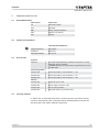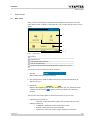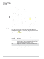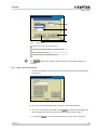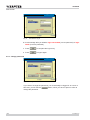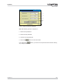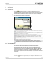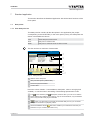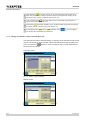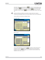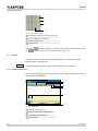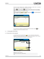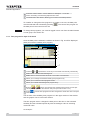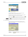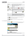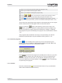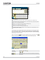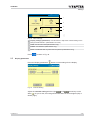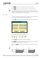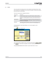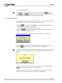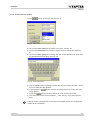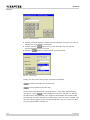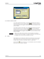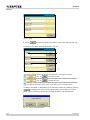
1
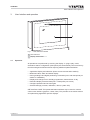
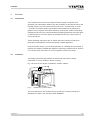
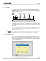
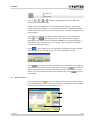
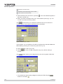
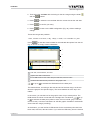
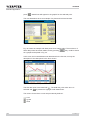
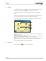
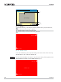
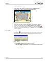
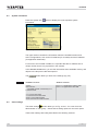
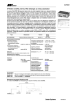
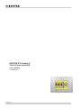
SAUTER EY-modulo 2
Touch Panel modu250
User’s Manual
7010060003 A
7010060001 A
modu250

2/52
7010060001 A
modu250
Content
Content
7010060001 A
1 General information
1.1
Safety information
1.2
Area of use
5
5
5
2 Important notes for use
2.1
Used abbreviations
2.2
Further documentation
2.3
Accessories
2.4
Training at Sauter
7
7
7
7
7
3 User Interface and operation
3.1
Operation
3.2
LED indicators
9
9
10
4 Overview
4.1
Introduction
4.2
Installation
4.3
Connections
4.4
Light-emitting diodes
4.5
Configuration
11
11
11
12
12
13
5 Start screen
5.1
Main menu
5.2
Login, logout
5.2.1 Login and enter password
5.2.2 Change password
15
15
16
17
18
6 Applications
6.1
Application list
6.2
Select an application
21
21
21
7 Standard application
7.1
Data points
7.1.1 View data-point list
7.1.2 Change command or value from data-point list
7.2
Alarms
7.2.1 Visualise alarm list
7.3
Time programs and calendar
7.3.1 Data points for time programs
7.3.2 Time program for days of the week
7.3.3 Time program entry
7.3.4 Time program for special days
7.3.5 Send time programs 7.3.6 Calendar
7.4
Historical data
23
23
23
24
26
26
27
27
28
29
30
31
31
33
3/52
modu250
Content
4/52
8 Settings
8.1
Calibration
8.2
Reboot
8.3
System information
8.4
Other settings
8.5
Display parameters
8.6
Clock
8.7
Profile
8.7.1 Password time-out
8.7.2 Create new user profile
8.7.3 Delete or edit user profile
8.8
Filters
39
39
41
41
42
43
44
45
46
46
49
49
Abbildungen
53
Index
55
7010060001 A
modu250
General information
1
General information
1.1
Safety information
Incorrect installation
Possible injury, fire, damage to equipment
ff For the operation of this device read this manual.
ff For the installtion of this device read the fitting instructions.
1.2
Area of use
The modu250 is a touch-panel with colour or monochrome display for visualising
and operating automation station data points of the line SAUTER EY-modulo 2
and the line of SAUTER EY3600 in a novaNet network.
Menu-driven operation works by directly touching the display. Installation lists,
setpoint parameters, time programmes, trend graphs and system settings may
be selected and edited without additional parameterisation. Passwords and user
rights provide effective security.
7010060001 A
5/52
modu250
6/52
7010060001 A
modu250
Important notes for use
2
Important notes for use
2.1
Used abbreviations
2.2
Abbreviation
Explanation
AS
Automation station
AUT
Automatic
BBf
Binary command address
MFA
Machine fine address
SW
Setpoint
Further documentation
modu250 (EY-OP250F001)
2.3
Fitting instructions
MV 505814
Datasheet
PDS 93.01
Materialdeclaration
MD 92.750
Accessories
Software
GZF 520*
Touch-panel parameterising software for Windows, for freely
designing the user interface
* Available directly from the extranet or implemented as a tool
in CASE Suite
Connecting cables
0367862 001
Connecting cable (1.5 m) modu250 <–> AS
0367862 002
Connecting cable (2.9 m) modu250<–> AS
0367862 003
Connecting cable (6.0 m) modu250 <–> AS
General
2.4
0374494 001
Stylus set for EYT 250
0374509 001
Power supply connector, 3-pin
0374515 001
Set for IP 65 protection
0374680 001
Individual seal (for set 0374515 001)
Training at Sauter
Fr. Sauter Ltd. or the Sauter branches in various countries can offer a training
course for touch-panel users. Information about available training courses can
also be found in the Sauter Seminar Programme.
7010060001 A
7/52
modu250
8/52
7010060001 A
modu250
User Interface and operation
3
User Interface and operation
1
2
Fig. 1
User interface modu250
1 LED indicators
2 Display, Touch Panel
3.1
Operation
All operations are performed by touching the display. In ‚plug & play‘ mode,
automation station configuration (data points) are automatically read out and may
thus be managed as follows without requiring additional parameterisation:
• Application display and selection (direct access to automation stations)
• Measured value, alarm and status display
• Issuing analogue and digital positioning commands (max. 200 data points per
station or installation)
• Display and change time or holiday programmes, date and time of day
• Read and display historical data (max. 3 data points per screen)
• Configure password and access rights
• General settings (contrast, calibration, reboot, system info)
GZF 520 F001 CASE TPC parameterisation software may be used to create a
custom user interface (graphics, charts, lists). This provides a convenient means
of implementing application-specific displays.
7010060001 A
9/52
modu250
3.2
LED indicators
LEDs above the touch-panel display information as follows:
• flashing green middle LED indicates that the power supply is OK
• flashing red outside left LED indicates an active alarm in an open application
10/52
7010060001 A
modu250
Overview
4
Overview
4.1
Introduction
The nova250 Touch Panel for the Sauter EY3600 system comprises local
operation of the automation stations with the possibility of bus-wide access to the
EY3600 system. The two variants of the touch-panel – monochrome or colour
– provide a convenient graphic presentation with operation from plant lists or
graphics, time programs and historical data by touching the surface of the panel.
Operational security can be implemented by assigning passwords and user rights
for different users. The touch-panel can be fitted into a motor control centre or
onto a top-hat rail.
These Operating Instructions aim to explain the basic functions of the touchpanel and to aid operation of the automatically created application.
In the rest of this section, you will find information on installing the touch-panel. If
the device is already installed and capable of functioning, please refer to sections
2 to 4 for the main instructions on correct operation of the touch-panel.
4.2
Installation
The Fitting Instructions (MV 505814) enclosed with the product contain
information on how to install the device correctly.
Fig. 2 shows how the device is installed in a switch cabinet.
186
138
2
1
Fig. 2
Installation in a switch cabinet
The touch-panel may also be fixed onto a top-hat rail. Accessory 0374515 is
available for a water- and dust-proof IP65 installation.
7010060001 A
11/52
modu250
4.3
Connections
Fig. 1‑2 shows all the connections. The touch-panel must be connected to a
power supply (230 V~ or 115 V~) with an earth protection wire and to the EY3600
novaNet system bus (RJ-11).
RJ 11 6/6
novaNet
230 V~
<7W
RJ 45
Ethernet
DB 9
RS232
N L
Fig. 3
Connections
As the power supply is permanently installed and is not in the low-voltage range,
the installation must be carried out by a trained specialist (technician, electrician
or installer).
The other connections such as the RJ-45 connection for Ethernet and the DB-9
interface (RS232) are used only for any application downloads and firmware
updates that may be needed.
NOTICE
4.4
You must select the correct cable for the novaNet connection in accordance with
the EY3600 specifications, in order to prevent interference on the data line.
Light-emitting diodes
B11352
The touch-panel has two light-emitting diodes
that are used. The
green one in the middle flashes when the touch-panel has the correct voltage
supply. The red light-emitting diode on the left flashes when an active application
is showing an alarm status.
Fig. 4
12/52
Touch-panel with light-emitting diodes
7010060001 A
modu250
Overview
The alarm LED never flashes in the main menu or in the application list menu, i.e.
if an application is not enabled.
4.5
Configuration
The touch-panel can be used directly, without configuration, with the Sauter
EY-modulo- and EY3600 system. When you do this, the configuration of the
automation stations is read automatically and the touch-panel application is
created. Sections 3 and 4 describe the standard functions and section 5 explains
the touch-panel settings.
If you do not wish to use this application, individual applications and dynamised
pictures can be created with the CASE Touch-panel Configurator (CASE TPC).
All the options that can be configured and programmed with the CASE TPC
require technical input and are not covered by these Operating Instructions. More
information is available in the CASE TPC manual. Sauter will be happy to provide
further information.
7010060001 A
13/52
modu250
14/52
7010060001 A
modu250
Start screen
5
Start screen
5.1
Main menu
After you have successfully connected and started the touch-panel, the main
menu start screen is called up automatically. This contains the top level of menu
items.
1
2
3
5
Fig. 5
B11354
4
Main menu
1 Settings
2 Application list
3 Login/logout (with password)
4 Time (in the status bar)
5 User (in the status bar): Default administrator, Logged out, no user
The touch screen is divided into three sections:1. Title bar: Menü-Überschrift (evt. mit Firmenlogo)
2. The central area is used to display the various functions and buttons as
depicted in Fig. 5.
3. Status bar: Displays the logged-in user with the current time. Also, the status bar often
contains the back arrow
, which is used to go back to the previous
window.
Touch one of the three buttons to select the function of your choice:• Application list (section 3)
• Selection of the automation station (AS) or plant that you want
• Settings (section 5)
• Calibration: calibration of the touch-panel screen
• Reboot: restart the touch-panel software
• System info: view the current system settings and versions
7010060001 A
15/52
modu250
Start screen
Other settings:• Display parameters: setting the screen contrast
• Clock: set the time
• Profiles: create users
• Filters: view, enable and disable filters
• Login/logout (section 5.2)
• User login or logout
• Change password
• To visualise and change all functions under Settings, you must be logged in as
a user in the administrator user group. See section 5.7.
• If you are an administrator, you can touch the time
in the status bar to
adjust the time.
• The title bar with the Sauter Logo and general main texts can be adapted to
individual requirements (OEM) on request.
• If the screen is not used after you have started the touch-panel, the
background illumination will be turned off automatically. If the background
illumination is not activated for about 60 seconds after starting, the touchpanel software will automatically return to the last application that was used.
5.2
Login, logout
on the start screen to view a dialogue for
Touch the Login/logout button
user login/logout (Fig. 6). You can also go to the same login/logout dialogue by
touching the name
of the user who is not yet logged in, or the name of the
logged-in user, e.g.
, in the status bar.
The list of user names shows all users who have been defined by the
administrator in the Profiles menu. See section 8.7.
In the original status, three users with different access rights are defined:User name
Description
---------
No user, only allows operation of the panel (without password).
Administrator
‚Default administrator‘, allows viewing all data points, entry of system
parameters, setpoints, switching commands and time programs and
requests of historical data (Default password: 654321).
User
‚Default user‘, allows viewing all data points, entry of setpoints, switching commands and time programs and requests of historical data
(Default password: 123456).
Guest
‚Default guest‘, allows viewing all data points and requests of historical
data (Default password: 1).
Tab. 1
16/52
Access rights
7010060001 A
modu250
Start screen
1
2
4
Fig. 6
B11355
3
Login/Logout
1 Password: box to enter the password
2 User name: dropdown list box to select the user
3 logs out the current user
4 saves the entry and accepts the login
The
selected.
button only appears when the user who is already logged in is
5.2.1 Login and enter password
B11356
1. To log in, first select the user name from the list box and touch the password
box (Fig. 6).
Fig. 7
Enter Password
ÂÂ You see a numerical keypad with a request to enter the password.
2. You can now enter the password. Press
to confirm the password, the
user is logged in and you are returned to the screen shown in Fig. 8.
3. If you press
7010060001 A
you are also taken back so you can cancel the login.
17/52
modu250
B11510
Start screen
Fig. 8
Successful Log-in
ÂÂ A red message tells you whether login succeeded (correct password) or login
failed (incorrect password).
4. Press
to complete the login entry.
5. Press
to logout again.
B11357
5.2.2 Change password
Fig. 9
Change Password
If you want to change the password, you must already be logged in as a user. In
this case, you will see the
button, which you have to press in order to
change the password.
18/52
7010060001 A
modu250
Start screen
1
2
3
4
Fig. 10 Entries to Change a Password
Make the following entries in sequence:1. Enter the old password
2. Enter the new password
3. Confirm the new password
4. Press the
button to save and return
If you press the
button, you return to the previous screen without making
any changes (Fig. 10).
7010060001 A
19/52
modu250
20/52
7010060001 A
modu250
Applications
6
Applications
6.1
Application list
Touch the
Application list button on the start screen to view a list of all
automation stations or plants that respond via the EY3600 system bus (novaNet)
and that meet the conditions for a filter, if one has been set (see section 8.8).
This list can have a maximum of 100 entries.
1
2
3
4
7
B11359
5
6
Fig. 11 Application List
6.2
1
Press on the Application column header or AS address to sort the lines in ascending
or descending alphanumeric order.
2
The AS address column shows the group address of the AS. If an application is distributed over several AS, an * is shown.
3
The Application column shows which applications have responded.
Depending on the definition in CASE FBD, this column shows the house address
or, if no definition is available, the default name (device with AS address, e.g. device-220) is shown.
4
All data are read again in the AS.
5
The data are read in the touch-panel‘s memory.
6
If a filter is active, a FILTER ACTIVE message is shown. See also section 8.8.
7
The logged-in user, time and back arrow for the main menu are also shown in the
status bar.
Select an application
The application that should be displayed can be selected from the list.
An application that has never been read or that you want to read again can
read all data from the AS (on the novaNet) by pressing
. The
button
therefore re-assembles the configuration (‘Update/actualise data points’), the
data points are registered and the values (analogue values, statuses, alarms) are
read afresh.
Press the
7010060001 A
button to trigger loading of all data points and pictures that are
21/52
modu250
Applications
assigned to this application. The
button guarantees that the current values
in the data-point list are read and registered on the AS (‘Activate data points’).
The data-point list is taken from the application in the touch-panel memory and is
not updated. In this case, only the values, statuses and alarms are read afresh.
As long as data are being polled (scanned), the message in Fig. 12 is shown.
Fig. 12 Please Wait
After the application has been updated or activated, either the data-point list or
the start screen for the application will appear.
Various types of touch-panel applications and visualisations are possible:a) If no project for this application is stored in the touch-panel, a data-point
list is shown. The loading window tells you: ‚Please wait, scanning AS, file
missing (scr_app_0_0.xml)‘.
b) If a project for this application is stored in the touch-panel, the assigned
start screen appears.
These instructions deal with the touch-panel Standard Application (that is a))
excluding design engineering with CASE TPC (see section 4.5).
22/52
7010060001 A
modu250
Standard application
7
Standard application
This section describes the Standard Application with all the basic functions of the
touch-panel.
7.1
Data points
7.1.1 View data-point list
This data-point list contains all the data points in the application (the project
corresponding to the CASE FBD). In the touch-panel (colour), the data points are
shown in three different colours.
Red:
Alarm data point, alarm active.
Blue:
Data point in remote mode.
Black:
Data point in automatic mode or alarm inactive.
This list can have a maximum of 200 entries.
1
2
3
4
5
6
7
8
11
B11362
9
10
Fig. 13 Data-point list
1 address of the data point
2 data point description (address text)
3 shows the physical variable
4 current value
Press the column header – house address, description, value or unit (physical
variable) – to sort the lines in ascending or descending alphanumeric order.
The
(house address) and
(description) buttons allow you to show or hide the
5 house address and address text columns, only the house address, only the address
text or only the value and physical variable.
6
button: use this button to activate the selected data point so you can make
changes to the status or (setpoint) values.
: this button enables you to define and view the pre7 Historical Database button
sentation of up to 3 values (see section 4.4).
7010060001 A
23/52
modu250
Standard application
: this button allows you to read special days that influence the
Calendar button
8 basic time program, or to define new special days. The special day display can be
defined for up to 2 years in advance (see section 4.3).
: this button allows you to read weekly time programs or
9 Time program button
specify new ones (see section 4.3).
: this button enables you to visualise all data points that are defined
10 Alarm button
as alarms and are currently active (see section 4.2).
, time
and back arrow
11 The logged-in user
tion list are also visualised in the status bar.
to go to the applica-
7.1.2 Change command or value from data-point list
The data-point list allows manual setting or changing of all data points that accept
remote commands or value changes. Select the relevant line with the data point;
you must press the
button in order to make the entry. These windows are
shown for binary values.
B11367
Automatic mode
Fig. 14 Binary Output, Automatic
B11368
Manual mode
Fig. 15 Binary Output, Switching Command
24/52
7010060001 A
modu250
Standard application
Automatic mode can be selected with
. To select a manual status for the
command the
button has to be deselected and the command as OPEN
or CLOSE, for example, can be choosen. Use the
button to close the
switching command. Use the
button to return to the previous screen (Fig.
13).
Statuses OPEN and CLOSE are specified command texts in the project
engineering (CASE FBD) and they may have different names for the application.
These windows are shown for analogue values.
B11369
Automatic mode
Fig. 16 Analogue Output, Automatic
B11370
Manual mode
Fig. 17 Analogue Output, Setpoint
You can select automatic mode with
. To select a manual value for the
analogue output the
button has to be deselected and the analogue
(setpoint) value as 23.0, for example, can be entered. Numerical buttons are
available to enter the numbers.
7010060001 A
25/52
modu250
Standard application
1
2
4
B11371
3
Fig. 18 Numerical entries
1 ‚Backspace‘ deletes the previous character
2 ‚Clear‘ deletes the whole entry
3 change prefixed sign
4 decimal point
Press the
button to apply the value and the window will be closed. Press
button to return to the previous screen (Fig. 13).
the
7.2
Alarms
If an alarm status is active in the selected application, the top left red lightemitting diode (LED) will flash.
NOTICE
The light-emitting diode is lit only when the application is activated.
7.2.1 Visualise alarm list
button in the data-point list to open a window with a list of
Press the alarm list
all active alarm data points.
1
2
3
4
6
B11372
5
Fig. 19 Alarm List
1 address of the data point
2 data point description (address text)
3 shows the physical variable
4 current value
26/52
7010060001 A
modu250
Standard application
Press the column header house – address, description, value or unit – to sort the
lines in ascending or descending alphanumeric order.
(house address) and
(description) buttons allow you to show or hide the
The
5 house address and address text columns, only the house address, only the address
text or only the value and physical variable.
, time
and back arrow
6 The logged-in user
list are also visualised in the status bar.
B11373
to go to the data-point
Fig. 20 Active Alarms
Fig. 20 shows an example of an alarm list with active alarms. Button
pressed to hide the house address column.
7.3
was
Time programs and calendar
7.3.1 Data points for time programs
By pressing the time program button
, you can visualise the existing time
program for specified data points or define another time program. Fig. 21 shows
a list of data points that can be linked to a time program.
1
2
4
B11375
3
Fig. 21 Time Program
1 address of the data point
2 data point description (address text)
7010060001 A
27/52
modu250
Standard application
3
Press the column header – house address or description – to sort the
lines in ascending or descending alphanumeric order.
4 The status bar is also shown, allowing you to return to the data-point list.
To visualise or change the time program or to create a new one, the data point
must be selected and activated by pressing
. The current time program for
the data point is then read from the AS.
NOTICE
To change time programs, you must be logged in as a user from the administrator
or user group. See section 8.7.
7.3.2 Time program for days of the week
Once the data point is selected, a window as shown in Fig. 22 will be displayed
(data point without weekday time program).
1
2
3
4
5
6
8
B11503
7
Fig. 22 Weekday Time Program
1 Columns
to
represent the seven days of the week from Monday until Sunday.
2 Time column: indicates the switching time
3 Value column: shows the value to be set or the status to be switched.
4 Allows you to change the selected existing time program entry.
5 Allows you to create new time program entries.
6 Allows you to delete the existing time program entry.
7 Buttons
or
switch over between the weekday time program and the special day time program for the relevant data point (see also section 7.3.4).
to exit the time programs and the configuration will be sent to the AS (see
8 Press
section 7.3.5).
The list view of the weekday time program is in the upper section of the window
and the graphic view is in the lower section.
The time program sets or changes the data point to the time on the activated
weekday and the activated special day with the analogue value or switching
command value.
An example:28/52
7010060001 A
modu250
B11504
Standard application
Fig. 23 Example of Time Program
If the selected data point has a time program, the time program is shown
graphically (in different colours) and in list form (Fig. 23).
In the example, the valve (‚Valve2‘) is opened at 8 o‘clock on Monday to Friday
(OPEN) and is closed again at 5 o‘clock (1700 hours) (CLOSE).
button (after selecting a line from the list) or the
When you press the
button, you see the window for making entries in the time program (Fig. 24).
NOTICE
Press
to delete the selected entry without further enquiries, except when
the time program entry is parameterised for both a weekday and a special day.
7.3.3 Time program entry
To make a time program entry, there is a window to parameterise the time
program values and switching commands, with the relevant timing, both for the
weekdays and the special days.
Fig. 24 Time Program Entry
Weekdays
Special days
7010060001 A
Monday
to Sunday
to
29/52
modu250
Standard application
Daily (
(disables) enables all weekdays and special days
)
Time
timing of switching command or value change
Value
switching status or analogue value
confirm entry
cancel entry
Weekdays, Monday
to Sunday
touch these buttons to enable (
) or disable (
) the desired weekdays for the switching command or the value change.
to
up to 8 special day time programs can be assigned to this data
point with the help of the calendar function (also see section
8.3.6).
Special days (
)
Time
You can set and change the switching time with the slider
,
or the forwards / backwards buttons (1-minute steps
).
30-minute steps
Value
Touch this box to open the window where you set values or
commands. In the window, you can set the analogue value or
switching command and confirm with OK. The new value or
command is shown (also see Fig. 14 to Fig. 18).
Press
to confirm the new or corrected entry for the time program. The
window with the graphic display appears again.
Press
to cancel the entry and go back to the graphic view without
accepting any changes.
7.3.4 Time program for special days
When you press
to switch over to the special day time program, you see a
window as shown in Fig. 25 (data point without special day time program).
1
2
3
4
5
6
8
B11505
7
Fig. 25 Special Day Time Program
1 Columns
to
show the eight special days.
2 Time column: indicates the switching time
3 Value column: shows the value to be set or the status to be switched
30/52
7010060001 A
modu250
Standard application
4 Allows you to change the selected existing time program entry.
5 Allows you to create new time program entries.
6 Allows you to delete an existing time program entry.
7 Buttons
or
switch over between the special day time program and the
weekday time program for the relevant data point (also see section 7.3.2).
in the time program to prepare for writing the time program to the AS.
8 Press
Before the time program is sent, you see a confirmation window (see section 7.3.5).
The list view of the special day time program for all 8 special days is in the upper
section of the window and the graphic view is in the lower section.
When you press the
button (after selecting a line from the list) or the
button, you see the window for making entries in the time program (Fig.
24). The procedure for making entries is the same as for editing or creating a
time program entry from the weekday time program view, as described in section
7.3.3.
Time programs that are defined in this way on the special days can then be
released for specified days using the calendar function (section 7.3.6).
7.3.5 Send time programs
in the weekday time program (Fig. 22) or the special day time
Press
program (Fig. 25) to prepare for writing the time program to the AS. Before the
time program is sent, you see a confirmation window.
Fig. 26 Send Time Program
Press
to send the time program for the data point to the AS. If you press
, the time program will not be sent and you ‘lose’ any entries that may
have been changed. In both cases, you exit the time program and go to the
overview of data points for time programs. Press
to stay in the weekday
or special day time program.
7.3.6 Calendar
Press the calendar button
to see the window shown in Fig. 27 (automation
station without defined calendar function).
7010060001 A
31/52
modu250
Standard application
1
2
3
4
5
B11506
6
Fig. 27 Calendar
1 The Start date and End date columns define the period for the calendar entry.
2
The Calendar column shows the definition of the calendar entry, either with special
day 1 to 8 or an assigned weekday.
3 Allows you to change the selected existing calendar entry.
4 Allows you to create a new calendar entry.
5 Allows you to delete the selected calendar entry.
6
is used to change the year calendar over in the graphic view. Special days can be
defined 2 years in advance.
The list view of the calendar entries (active special days) is in the upper section
of the window and a graphic view of the yearly calendar with visualised special
days is in the lower section. Special day periods are shown in red and individual
special days are shown in blue.
When you press the
button (after selecting a line from the list) or the
button, you see the window for making entries in the calendar (Fig. 28).
Fig. 28 Calendar Entry
Weekdays
Special days
Monday
to Sunday
to
buttons and slider to set the start and end dates of the special
day period
32/52
7010060001 A
modu250
Standard application
confirm entry
cancel entry
Click on
to
or
to
to select a desired special day or a (different)
weekday for the calendar entry.
A time program for a data point can use these special days (e.g. ‘special day
period during works holidays’), or it uses a time program for a different weekday
instead of the time program for the real weekday (e.g. ‘Sunday time program on a
public holiday’).
The period (from start to end date) for the calendar entry can be set with the
slider
or with
(‘special day period’). The slider resolution changes
depending on the date box that is activated (DD/MM/YYYY: day/month/year). If
the calendar entry is defined only on one specific day, the start and end dates
must be identical (‘special day’).
in the calendar (Fig. 27) to prepare for writing the (2‑year) calendar
Press
to the AS. Before the calendar is sent, you see a confirmation window.
Fig. 29 Send Calendar
Press
to send the calendar to all AS that are connected to the novaNet or
are included in any filter that may be activated. If you press
, the calendar
will not be sent and you ‘lose’ any entries that may have been changed. In both
cases, you exit the calendar and go to the data-point list. Press
to stay in
the calendar.
7.4
Historical data
Press the historical data
button in the data-point list to open a window with a
list of all data points (Fig. 30). This is the ‘interactive’ configuration for the graphic
view of historical data for up to three data points.
1
2
B11508
3
Fig. 30 HDB Configuration
7010060001 A
33/52
modu250
Standard application
1 definition of the time axis
2 definition of the value range in the Y-scale
3 read and show historical data
ff Select the data point and add it by pressing . The house address appears in
the blank ‚unused‘ box.
ÂÂ When you add an analogue value, the Y-scale window opens (Fig. 31). The
Y-scale is not active for binary values.
The
buttons allow you to adapt the defined minimum and maximum
Y‑scale values for the relevant data points that were added.
Fig. 31 Value Range, Y-scale
In this window, you can define the Y-scale for the data point with min. value and
max. value by pressing the number keys (also see Fig. 18).
ff Press
ff Press
change.
The
to confirm your entry.
to return to HDB configuration (Fig. 30), without making a
button allows you to adapt the time axis for the graphic HDB view.
Fig. 32 Time Axis, X-scale
1. First, define the desired (time) range for reading the HDB using the
buttons or the slider
.
34/52
7010060001 A
modu250
Standard application
2. Then select the end date with the timing for the time range using the slider
and the
buttons.
3. Press
to select the current date with the current time as the end date.
4. Press
to confirm your entry.
5. Press
change.
to return to the HDB configuration (Fig. 30), without making a
These time ranges are possible:1 hour, 4 hours or 12 hours, 1 day, 7 days, 1 month, 3 or 6 months or 1 year.
Press
to read the historical data for the selected data points from the AS.
Fig. 33 shows an empty historical database.
1
2
3
B11509
4
Fig. 33 HDB Ansicht
1 start date, house address, end date
2 graphic view with scroll function
3 list of HDB entries for the active data point with date, time and value
4 visualises the selected entry with lines in the graphic view
,
or up to
to activate the HDB entries for the data point
The date and time, according to the start and end of the time range, are shown
above the graphic view (left and right). The house address is at the top in the
middle.
In the centre, you see the box for the graphic view of up to 3 data points. The
HDB entries are shown connected with a straight line. Use buttons
,
or up
to
to activate the data point (white is active, the line is bold; grey is inactive,
the line is thin). Use the scroll buttons to shift the graphic forwards or backwards
around the time range (‘scrolling’).
At the bottom, you see the list of HDB entries for the active data point that have
been read, with time, date and value. If you select an HDB entry from the list and
7010060001 A
35/52
modu250
Standard application
press
, dotted lines will appear in the graphic for the selected point.
B11494
The next illustrations show an example of a plant and its historical data.
Fig. 34 HDB Configuration, Example
Fig. 34 shows an example with data points for a heating plant. The maximum of
three data points have been added, and by pressing
they could be shown
as a graphic as depicted in Fig. 35.
B11495
In this case, the house address was deactivated in the list view, so only the
description of the data points in the list is shown.
Fig. 35 HDB View, Example
The first data point is activated with
. The HDB entry with value 62.71 is
selected and
is pressed to highlight it with dotted lines.
The colours for the three curves are permanently defined:= red
= green
= blue
36/52
7010060001 A
modu250
Settings
8
Settings
As described in section 2.1, it is possible to make various settings for the touchpanel. Press the settings button
in the main menu to see Fig. 5‑1.
To change all settings, you must be logged in as a user in the administrator
group.
A user who is not logged in (‘no user’) and users from the Guest user group can
only call up the calibration, the system info and the reboot settings.
A user in the ‘user’ group can also access the display parameters, accessible
under more settings.
1
2
3
B11496
4
Fig. 36 Settings
1
Calibration: If a button cannot be correctly assigned to the action, a calibration must
be carried out. (all)
2 Reboot: reboots the touch-panel. (all)
3 System info. Important system information can be visualised. (all)
4 More settings. This button takes you to more settings. (user and administrator)
The next sections describe these and other settings.
8.1
Calibration
Press the Calibration
7010060001 A
button to start the calibration.
37/52
modu250
1
3
B11497
2
Fig. 37 Calibration
1
this button allows you to change the existing calibration. After you press the button,
the calibration starts and Fig. 5‑3 appears.
2 this button lets you return to the main menu.
3 this button lets you close the window being displayed.
Fig. 38 Calibration Points
For a new calibration, you must press briefly in the centre of the circle at the top
right and then in the circle at the bottom left.
NOTICE
38/52
You are recommended to use a pen or pencil for this setting. If this operation has
been performed correctly, you are taken back to Fig. 37.
7010060001 A
modu250
Settings
Fig. 39 Calibration Error
B11498
If the calibration has not been successful, you see the Calibration error
message as in Fig. 39. You must perform the calibration again.
Fig. 40 Calibration Test
Press on the area with your finger or a pen/pencil, and without interrupting the
pressure, check the active zone of the ‚Start calibration‘ button (follow the
arrow). If the zone becomes active (white) exactly on the edge of the button ,
the device is correctly calibrated; otherwise, the calibration must be repeated until
precision is attained.
8.2
Reboot
Press Reboot
to restart the touch-panel. This may be useful in certain cases;
after you press the button, you see a confirmation window as shown in Fig. 41.
Fig. 41 Reboot
ff Press
ff If you press
7010060001 A
to trigger the reboot of the touch-panel.
, the reboot action is not performed and the window closes.
39/52
modu250
8.3
System information
button to display the most important system
B11498
Press the System info
information.
Fig. 42 System Info
The upper section contains the information about the installed versions and
active configurations, such as the PC address (for novaNet) and the IP address
(for application download).
For access to the EY3600 novaNet, it is important that the PC address has a
unique number that is not yet present in the network.
In the Current screen area, you see the information about available memory and
objects in the last picture that was opened.
The
NOTICE
button takes you back to the settings (Fig. 36).
Hardware versions
Software versions
Colour…
Monochrome…
…with HDB and with functionality for a
hardware reset
Up to 1.2.x Applications without HDB
From 1.3.x Applications with HDB
3.1.1 Colour with HDB
3.1.2 Monochrome with HDB
XX.X.1 Colour without HDB
XX.X.2 Monochrome without HDB
8.4
Other settings
The Other settings
button takes you to Fig. 43 and – for a user from the
administrator or user group – shows further setting options for the touch-panel.
These other settings are briefly described in the following sections.
40/52
7010060001 A
modu250
Settings
1
2
3
B11500
4
Fig. 43 Other Settings
1
Display settings (parameters). Use this button to adjust the contrast setting for the
background illumination. (administrator and user)
2 Clock: sets time and date (administrator only)
3 Profile: user definition (administrator only)
4 Filter: to disable/enable any filters that are present (administrator only)
Press
to return to Fig. 36.
8.5 Display parameters
Press the Display parameters
button to show settings for the display.
Fig. 44 Contrast Setting
Adjust the contract setting with the right
or left
arrow keys or the
slider
. As you do this, the background illumination becomes brighter (left) or
darker (right).
7010060001 A
41/52
modu250
Settings
Press
to return to the settings without making any changes.
Press
to save the new setting and return to the settings (Fig. 43).
The background illumination has a guaranteed lifetime of 10,000 hours and it
switches off automatically after one minute if no operations are performed. Touch
the screen to reactivate the background illumination.
8.6
Clock
If you detect a discrepancy between the time shown in the touch-panel and the
real time, you can set the time and date on the touch-panel.
clock button or the time shown at the bottom right to display Fig.
B11502
Touch the
45.
Fig. 45 Clock Setting
The information appears in the boxes as follows:-
HH
MM
Use the
SS
DD
MM
YYYY
buttons to adjust the values in the boxes.
to accept the entries; the time and date are sent to all AS that are
Press
connected to the novaNet and the window closes.
If you press
same.
, no entries are accepted and the time and date stay the
Time
42/52
Date
HH:
hours (in 24h)
DD:
day
MM:
minutes
MM:
month
SS:
seconds
YYYY:
year
7010060001 A
modu250
Settings
8.7
Profile
The touch-panel can manage various user profiles with password input. These
user profiles can be assigned to one of three user groups, and they are saved in
the touch-panel as user profiles.
The three user groups are defined as follows:User group
Description
Guest
User with viewing rights only (as well requests of historical data)
User
User with viewing rights, with rights for historical data requests and
the option of entering setpoints, switching commands and time programs.
Administrator
User with viewing rights, with rights for historical data requests and
the option of entering system parameters, setpoints, switching commands and time programs.
No group
This group cannot be selected and is only used internally for a user
who has logged out (‚no user‘), who also has viewing rights only.
To make changes in the Profile settings, you must be logged in as an
administrator.
button to see Fig. 46.
B11511
Profile
Fig. 46 Profile
The user list shows all defined users. Use these three buttons:
,
and
to create new user profiles, and edit or delete existing profiles.
The password time-out section defines a period after which a user is
7010060001 A
43/52
modu250
Settings
automatically logged out.
If the logged-in user (administrator) is selected, only button
is shown.
The
and
buttons are not visualised. This means that at least
one user in the administrator group will always be present.
8.7.1 Password time-out
In the Password time-out area at the bottom (see Fig. 5‑11), you can define the
time after which a new login is required (‘Automatic logout’)
ff Use the
buttons or the slider
to adjust the setting. You have the
following options for password time-out:1 min., 5 min., 10 min., 30 min., 60 min. and none.
ff Use the
button to acknowledge the selected setting. The time-out will
then be active for all defined users.
If the time elapses with no further action on the screen, Fig. 47 appears:-
Fig. 47 Password Time-out
ff Press
ff Press
to go automatically to the window for a new login (see Fig. 6).
to return to the main menu with automatic logout.
If a user is in a window with special access rights, the user must log in again with
the same access rights, otherwise an error message as shown in Fig. 48 may
appear.
Fig. 48 Error Message for Access Rights
If you cannot log in again with the same access rights, you can simply press
to return to the main menu and log in again.
If password time-out is activated, it is advisable to leave the touch-panel in a
condition where all users from all user groups can log in again.
44/52
7010060001 A
modu250
Settings
8.7.2 Create new user profile
Press
in Fig. 46 and you will see Fig. 49.
Fig. 49 New User
ff Click on the User name box to define a new user. See Fig. 50.
ff Click on the Password box to define a password for this new user. See Fig.
51.
ff Click on the User group box to assign the user to the relevant user group with
the appropriate access rights. See Fig. 52.
Fig. 50 Enter User Name
ff Use the alphanumeric keyboard to define the new user name. At least 1 and at
most 15 characters are allowed.
ff Confirm with the
button and you are returned to Fig. 49 with the user
name filled in.
ff Press the
button to return without an entry for the user name.
ff The space bar is used for an underline _ . Also see Fig. 18 for more special
keys.
If a user profile is created with a user name that already exists, the existing user
profile will be overwritten.
7010060001 A
45/52
modu250
Settings
Fig. 51 User Password
ff Use the numerical keypad to define the new password. A minimum of 1 and a
maximum of 16 characters are allowed.
button and you are returned to Fig. 49 with the
ff Confirm with the
relevant password for the new user.
ff Press the
button to return without a user password.
Fig. 52 User Group
Finally, one of the three user groups must also be assigned.
: confirms the entries for the new user.
: cancel entries for the new user.
Once entries have been made in all three boxes – user name, password and
user group – press
to acknowledge the new user and then you will see
the input box for the password of the logged-in administrator who wants to add
the new user. Once this has been correctly entered, the new user is created. The
new user will now appear in the user list as depicted in Fig. 53, should you wish
to log in as described in section 5.2.
46/52
7010060001 A
modu250
B11512
Settings
Fig. 53 New User List
8.7.3 Delete or edit user profile
If you want to delete a user profile, you must select the relevant user from the
. You will see a request to
user list as shown in Fig. 5‑11 and then press
enter the password for the logged-in administrator. If this is successful, the user
profile is deleted.
If you want to change a user profile, you must select the relevant user from the
user list as shown in Fig. 5‑11 and then press
. You can change the
password and user group and confirm with
. You will also see a request to
enter the password for the logged-in administrator. If this is successful, the user
profile is changed.
NOTICE
8.8
• Editing a user profile can be useful if a user has forgotten his password.
• A user name cannot be changed. To change the user name, the profile has to
be deleted and a new one must be created from scratch.
Filters
Filter definitions can be made with CASE TPC and loaded into the touch-panel.
Filter definitions allow you to limit the touch-panel to a restricted range in the
EY3600 system, with filters for automation stations or applications.
button to show Fig. 54. In this illustration, there are no defined
Press the Filter
filters which can be enabled or disabled.
7010060001 A
47/52
modu250
B11513
Settings
Fig. 54 Filter
ff Press
to close the window and return to the other settings (Fig. 43).
An example of a filter definition is shown in Fig. 55.
1
2
B11514
3
Fig. 55 Filter Definition - Example
1
AS (automation station): an AS filter is defined but not enabled (activated)
. Click on
to activate the filter.
2
Application: an application filter named ‚novaTherm 200‘ is defined and activated
. Click on
to disable the filter.
3
Calendar: a calendar filter with the application name is also defined and activated.
Any calendar that is sent (see section 4.3.6) will go only to this application.
If a filter is activated or deactivated and if the Filter window is closed by pressing
, a dialogue box (Fig. 56) will appear asking you to reboot the touchpanel. This is necessary so that the new filter definitions can be activated.
Fig. 56 Reboot to Activate Filters
48/52
7010060001 A
modu250
List of figures
List of figures
Fig. 1
Fig. 2
Fig. 3
Fig. 4
Fig. 5
Fig. 6
Fig. 7
Fig. 8
Fig. 9
Fig. 10
Fig. 11
Fig. 12
Fig. 13
Fig. 14
Fig. 15
Fig. 16
Fig. 17
Fig. 18
Fig. 19
Fig. 20
Fig. 21
Fig. 22
Fig. 23
Fig. 24
Fig. 25
Fig. 26
Fig. 27
Fig. 28
Fig. 29
Fig. 30
Fig. 31
Fig. 32
Fig. 33
Fig. 34
Fig. 35
Fig. 36
Fig. 37
Fig. 38
Fig. 39
Fig. 40
Fig. 41
Fig. 42
Fig. 43
Fig. 44
Fig. 45
Fig. 46
Fig. 47
7010060001 A
User interface modu250
Installation in a switch cabinet
Connections
Touch-panel with light-emitting diodes
Main menu
Login/Logout
Enter Password
Successful Log-in
Change Password
Entries to Change a Password
Application List
Please Wait
Data-point list
Binary Output, Automatic
Binary Output, Switching Command
Analogue Output, Automatic
Analogue Output, Setpoint
Numerical entries
Alarm List
Active Alarms
Time Program
Weekday Time Program
Example of Time Program
Time Program Entry
Special Day Time Program
Send Time Program
Calendar
Calendar Entry
Send Calendar
HDB Configuration
Value Range, Y-scale
Time Axis, X-scale
HDB Ansicht
HDB Configuration, Example
HDB View, Example
Settings
Calibration
Calibration Points
Calibration Error
Calibration Test
Reboot
System Info
Other Settings
Contrast Setting
Clock Setting
Profile
Password Time-out
9
11
12
12
15
17
17
18
18
19
21
22
23
24
24
25
25
26
26
27
27
28
29
29
30
31
32
32
33
34
34
35
35
36
37
39
40
40
41
41
41
42
43
43
44
45
46
49/52
modu250
List of figures
Fig. 48
Fig. 49
Fig. 50
Fig. 51
Fig. 52
Fig. 53
Fig. 54
Fig. 55
Fig. 56
50/52
Error Message for Access Rights
New User
Enter User Name
User Password
User Group
New User List
Filter
Filter Definition - Example
Reboot to Activate Filters
46
47
47
48
48
49
50
50
50
7010060001 A
modu250
Index
Index
A
Abbreviations
Accessories
Access rights
Alarms
Application list
Area of use
C
Calendar
Calibration
CASE Touch-panel Configurator
Clock
Configuration
Connections
27
37
13
42
13
12
D
Data points
Datasheet
Delete user profile
Display parameters
23
7
47
41
F
Filters
Fitting instructions
47
7
H
Historical data
33
I
Installation
11
L
LED-Anzeigen
LED indicators
Light-emitting diodes
Login
Logout
10
9
12
16
16
M
Main menu
Materialdeclaration
Monochrome display
15
7
5
O
Operation
7010060001 A
7
7
16
26
21
5
9
51/52
modu250
Index
17
S
Safety information
Software
Start screen
5
7
15
T
Time programs
Training
27
7
U
User Interface
9
© Fr. Sauter AG
Im Surinam 55
CH-4016 Basel
Tel. +41 61 - 695 55 55
Fax +41 61 - 695 55 10
www.sauter-controls.com
[email protected]
52/52
Printed in Switzerland
P
Password
7010060001 A