1
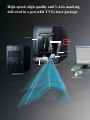
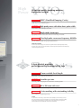
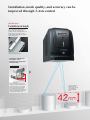
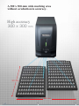
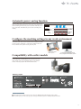
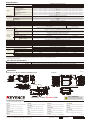
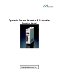
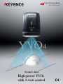
NEW
3-Axis YVO4 Laser Marker
MD-V9900A Series
World’s first
High-power YVO4
with 3-Axis control
High-speed, high-quality and 3-Axis marking
delivered in a powerful YVO4 laser package
Power monitor
Z-axis scanner
X-axis scanner
Y-axis scanner
Camera
3-Axis YVO4 Laser Marker
MD-V9900A Series
PC software
(MARKING BUILDER2)
2
High
Power
Ultra-high quality marking enables
high-power output
World’s first
DEPC (Dual End Pumping Cavity)
Double the power of traditional systems
World’s first
High peak power with ultra-short pulse width
Sharp marking without damaging the product
Best in its class
Single mode beam spot
High quality laser beam creates clear contrast on a wide range of materials
World’s largest range
Ultra-high pulse recurrence frequency 400 kHz
Smooth marking is possible on high speed production lines
YVO4 laser marker
The YVO4 laser marker employs YVO4 as its laser crystalline media for stable high-quality marking.
Currently, YVO4 crystal is one of the best media for superior high-power performance and stability using
a diode pumping solid state laser.
3-Axis control provides
performance that is ahead of its time
World’s first
42-mm variable focal length
Significantly reduces setup time and man-hours
World’s first
Variable spot size
Defocusing without changing the size of characters or marking position
Largest in its class
300 x 300-mm wide area
Covers a wide area without attenuating the laser accuracy
World’s first
3-Axis marking with outstanding visibility
Precise marking on irregular target shapes
3-Axis
For the first time in the industry, a laser marker has the capability to perform marking not only in
the X and Y directions, but also the Z direction! The 3 axis motion allows for outstanding visibility
on deformed or curved surfaces, and makes it easy to mark targets that vary in height. This
makes the MD-V the most versatile laser marker on the market today.
3
High-power YVO4 laser balances marking time
reduction with high quality
More than double
the optical exchange
efficiency of
conventional
systems
DEPC
(Patent pending)
The MD-V9900A Series is equipped with the newly developed DEPC (Dual End Pumping Cavity). The DEPC significantly
improves the optical exchange efficiency compared to that of a traditional end pumping system. This higher efficiency means
that the diode has to use less current to generate the equivalent power, reducing energy consumption and increasing diode life.
Lens
Q switch
Mirror
Crystal
One direction
beam
Efficiency
is more
than doubled
Traditional end pumping
Lens
Crystal
Beams from
two directions
Q switch
Mirror
Lens
Bearings (black coloration marking)
World’s best
DEPC (Dual End Pumping Cavity)
100 kW peak power & short pulse laser
With a peak power of 100 kW (triple the peak power of conventional systems), the MD-V9900A can achieve sharp, high
quality marking on hardened surfaces. This 100 kW is also generated with an incredibly small pulse width, reducing the
possibility of thermal damage to the target surface.
Peak power
100
100 kW
MD-V9900A
80
60
40
30 kW
MD-V9600
20 kW
Laser markers of
other companies
20
0
Pulse width
4 ns
8 ns
30 ns
Digital camera enclosure
(alumite removal)
4
High peak power
Useful for metal digging or resin coloration
Short pulse width
Less thermal damage on target surface
More than
three times
the peak power
Best in its class
Single mode beam spot
The MD-V Series utilizes an end-pumping YVO4 laser system that generates an ideal laser beam.
Conventional systems are forced to employ a multi-mode laser, leading to fluctuations in laser power and
target quality. Single mode laser’s concentrate the beam to provide high quality marking on a wide range of
surfaces.
Power peaks are concentrated on
the center of the beam.
Furthermore, ultra-short pulse
marking enables sharp marking
without adding extra stress.
MD-V marking photo
300x
MD-V power distribution
Peaks of power exist randomly in
the beam. This is equivalent to using
a lot of low powers to mark
characters on a target surface. It is
difficult to mark characters uniformly.
ITO film (coating removal)
World’s largest
range
Traditional YAG marking photo
300x
Traditional YAG power distribution
Ultra-high pulse recurrence frequency
400 kHz
The MD-V9900A Series employs a Q switch
frequency more than double that of previous
KEYENCE lasers. The high frequency enables
smooth marking of fine resolutions on high speed
productions lines. Both continuous wave and pulse
oscillation are available to accommodate varying
surface conditions
When sped up
MD-V9900A
Marking with
traditional speed
Accurate marking with
no space in between
Traditional laser
With spaces between dots
Transistor (coloration marking)
Stability ±2%
Adjustable over a wide range from CW (continuous
wave) to 400 kHz pulse
Power linearity
The power linearity of traditional laser systems is
typically +/-5%, and could be even larger at low
power. The MD-V9900A achieves and incredible
+/-2% power stability, meaning that the marking
will never chip, burn, or blur.
Laser
output (W)
Other laser markers
MD-V9900A
MD-V
Output
stability ±2%
Traditional lasers Unstable especially
at low output
Keys on a mobile phone
(coat peeling)
5%
100%
Set value of power
5
Installation, mark quality, and accuracy can be
improved through 3-Axis control
World’s first
Variable focal length
The 3-Axis laser control (X, Y and
Z-axes) sets the maximum spot
position at any focal length. The focal
length can be set within a 42-mm
range without attenuating the flatness
of the marking area.
Enclosure made of resin
(marking on stepped surfaces)
Significant reduction in
installation costs
minimizes the setup time
and man-hours
Traditional model
Jigs or height adjustment equipment
is necessary.
A vertical adjustment mechanism was
necessary to move the laser head to the
proper focal distance, or the focal point
had to be adjusted for each workpiece
using a suitable work placement jig.
Setting the vertical adjustment mechanism
or placing a suitable work placement jig
demanded high installation costs.
6
The focal length is set
arbitrarily within the
42-mm range. The wide
range significantly
reduces installation
time.
World’s first
Variable spot size
Varying the spot size of the laser is helpful when trying to
enhance the contrast of characters on specific materials, or
engrave more deeply into the target surface. Typical defocus
techniques may cause varying character size and position,
while the MD-V can provide uniform quality of characters.
Traditional model
Reference focus position
Position, size or
thickness deviates.
MD-V
Variable focal
point
Marking in a set
thickness at a set
position
LSI (High accuracy marking with defocusing)
World’s first
3-Axis marking
The MD-V9900A Series features 3-Axis control to modify
the laser position according to the shape of a target, which
can include steps, inclined surfaces, cylinders or circular
cones. The MD-V9900A Series minimizes distorted, worn or
chipped characters while enabling uniform marking on
three-dimensional surfaces that are considered untouchable
by conventional markers.
Print comparison
Steps
Lower
Upper
Lower
Worn
Traditional
model
Upper
MD-V
Inclined surfaces
Traditional
model
Worn, Stretched
MD-V
Cylinders
A switch on an instrument panel
(marking on a 3D solid)
Traditional
model
Distortion,
Stretched
MD-V
Circular cones
Traditional
model
Deformation
MD-V
7
A 300 x 300-mm wide marking area
without a reduction in accuracy.
High accuracy
300 x 300 mm
300 mm
300 mm
8
10
20
30
Largest in its class
300 x 300-mm wide area
Mounting position Correction
Marking in a large area often requires moving a
target workpiece using an X-Y stage, or
switching the lens on a conventional laser to
create a wide marking area. Using an X-Y stage
increases integration costs and time, and also
decreases product throughput. A wide area lens
can help these problems, however characters are
often displaced or blurred at the edge of the
marking area. The MD-V9900A Series utilizes a
special lens system along with its unique 3-axis
control to create a highly accurate 300 x 300-mm
wide marking area, eliminating the need for
mechanical adjustment while maintaining
character integrity.
The dedicated software easily
corrects the head inclination
after integration using X, Y
and Z-axes, without the need
for mechanical adjustment.
This feature significantly
reduces the man-hours for
installation.
20
Head
misalignment
Before correction
After correction
The KEYENCE advantage
when marking over a wide
area:
Problems associated with the
properties of the Fθ lens of
conventional systems have been
eliminated, so characters stay clear
and crisp over the entire marking area.
Traditional Area distortion due to lens
characteristics
model
Pallet marking
MD-V
Area in which deformation and
distortion are corrected
10
Identical characters or serial numbers can easily be marked at high
speed on multiple workpieces, such as electronic components in a
tray. The MD-V can disable marking or correct inclination for
individual targets. Additionally, the dedicated communication
algorithm significantly reduces coordinate adjustment via
communication lines.
Area center
Area edge
No characters are
displaced or worn.
The marking angle can be
corrected individually.
Marking can be set to disable/
enable individually.
No defective marking
0
9
Dedicated software simplifies setup
Marking Builder 2
(2D & 3D)
*OPTION
With the Marking Builder 2 software, two dimensional marks can be attached easily to three dimensional figures on the screen. Anyone
can set the best suitable marks on a variety of shapes including steps, cylinders, inclined surfaces, circular cones and more.
Basic operation
marks in the two dimensional
Step 1 Edit
setting window
Step 2 Select a figure
Select a figure from the standard four figures, which
includes a flat, cylinder, sphere or circular cone, and
attach the mark on the selected figure.
Flat
Cylinder
Sphere
3D editing tool (MB-H3D2)
Circular cone
Step 3
Marking Builder 2 software
Organize marks in the three
dimensional setting window
Font Architect
In addition to the 2 standard fonts, it is possible to add 10 fonts.
Flexible printing for each user.
Original font
x
2
User font
x
10
It is possible to freely alter the font from the
registered system font. It is also possible to
differentiate within settings.
Easy Palette setting
Marks can be viewed and
inspected stereoscopically
by changing angles at your
command.
Maximum of 65,025 units allocated in a bundle.
Wafer layout before dicing is speedy and true because easy
layout and individual print setting is possible.
Assign individual print locations.
Loading from a CSV file is also possible.
10
Easy layout with Marking Builder.
Realize a significant reduction of working
hours for edit work.
Step 4 Mark the target
Logo designer
*OPTION
Logo designer is a new application within Marking Builder 2 that can import DXF files, do various pattern fill effects,
and also select areas to fill.
Success is easily achieved by importing various designs in order to get the optimal conditions for the printing target.
List
Select the coordinates from the displayed
list. The stroke order can be freely
changed.
Disconnected line detection
The disconnected part of the contour line is
displayed. Even when a complex design is
imported and the connections aren't perfect,
contour lines can be easily connected.
Various hatching functions
Fill effects of designs such as a logo can
easily be changed without using CAD. The
hatching pattern can select diagonal lines,
intersecting lines, contour lines, etc. and
optimally fill according to the marking
target.
Closing lines
Illustrator plug-in
Diagonal lines
Intersecting lines
Contour lines
*OPTION
It is possible to load logo mark designs created in Illustrator directly into Marking Builder.
After loading, parameter editing of hatching adjustment can be done in the edit screen.
Create logo design graphics with Adobe® Illustrator®
Load into Marking Builder directly as a logo mark.
Create designs with Illustrator
Hatching editing can be done easily in the Marking Builder screen.
*Adobe® Illustrator® is a registered brand of Adobe.
11
Improve productivity with our ...
NEW
Viewfinder function
There is a built-in camera inside the laser marking head. Unlike an external camera, it is possible to confirm the position adjustment and marking
results with the built-in camera since the image doesn't shift when marking.
Alignment view function
It is possible to adjust and confirm the marking position by displaying the
characters and logo on the viewfinder screen. Anyone can easily and surely mark
because it is possible to configure the workpiece marking using the software.
Advantages of the built-in viewfinder
Even with little effort, it is easy to adjust the positioning.
When using the built-in camera, it is possible to confirm the position
adjustment and marking results since the image doesn't shift when marking.
It is possible to adjust the position with the protective covering done.
It is possible to use concentric shooting
to eliminate position slipping
Z-MAP Creator
*OPTION
3D-CAD can be imported to Marking Builder as a bedsill of the tridimensionality marking. Achieve 3D image marking
with shapes that are not expressible with basic marking.
3D-CAD data (STL format) can be
converted into Z-MAP (Marking Builder only
data) with the touch of a button. After the
conversion, the CAD data is used as a
foundation and it is possible to change the
characters and logo.
3D-CAD (STL format) Screen
Z-MAP Screen
High Resolution Photographical marking function
The “High-res” Photographical marking” function
that accurately duplicates high quality graphics is
on board. Because of the fine control possible with
the YVO4 laser, the realistic sensation of a picture is
duplicated as it is with laser marking.
12
Conventional
“High-res”
Photographical
marking
Variable distance pointer
(Patent pending)
Two types of red guide beams show the optimum
marking distance on a workpiece. Different from
traditional pointers, the focal point can be focused based
on the pointer’s position without changing the laser head
or workpiece height.
+21 mm
±0
–21 mm
Traditional laser marker
There is only one focal point. The height of
the head or that of the marking area should
be adjusted according to the workpiece.
MD-V9900A Series
The focal point can be adjusted without
changing the height of the laser head or that
of the workpiece if the marking area is within
the focal length (within ±21 mm).
Variable spot sample marking function
In addition to the traditional combination of laser power,
marking speed and Q-switch frequency, the variable spot
sample marking function features a useful feature that
marks characters while changing the spot size (focal
length). The best marking condition can be determined
from the marking results. Even novices can find the best
marking condition quickly for difficult mark settings
such as shallow marking on electronics components
(resins) or black marking on tools (metals).
Traditional sample marking function
The spot size is fixed. Only the laser power,
marking speed and Q-switch frequency can
be set.
Variable spot sample marking function
In addition to the traditional functions, it is
possible to set various conditions while
changing the spot size.
Multiple guide laser beams
The Marking Builder 2 software is equipped with a
multiple guide laser beam function that allows for easy
alignment of target marks. Choose to project the entire
marking area, the exact position of each mark, or the
shape of the target workpiece. Utilizing the guide lasers
will ensure your marks will never be out of position
again.
Frame of the marking area
(An area where characters could be marked is
displayed.)
Image of a target workpiece
(The outline of a marking target is displayed.)
One or continuous guide laser beam radiation
(Characters to be marked are displayed.)
Marking areas
(Marking areas are displayed.)
13
Accelerate automation processes with our ...
Built-in power monitor
(Patent pending)
Along with a system to verify the output value of the laser,
the MD-V9900A also employs an internal system to monitor and
automatically adjust for power variations that may occur over the
lifetime of the laser. This feature will help to ensure that each mark is
made with the same quality and consistency, regardless of the operator
or age of the marking head.
Advantages of the built-in power monitor
Automatic power measurement and correction
Quick measurement without moving equipment
No variation caused by individual operators
Laser power check
13.00W
External equipment connection
Follow-up marking on a rotating
workpiece
Characters or logos can be marked while following a rotating workpiece.
Rotation does not have to be stopped. Not only is the complex control
simplified, but the follow-up marking function also improves the quality
and significantly reduces tact time.
+ Servo motor with positioning
function
MV Series
Micrometer
Adjusting the mark according to
a change in distance
Change in distance to a target workpiece is perceived in real time by
receiving an analog output. The LK-G Series helps to mark characters while
varying the focal length.
+ High speed and high accuracy CCD laser displacement sensor
LK-G Series
Automatic marking of barcode
information
Data read with a barcode reader can be transferred to the laser marker
without using external control devices such as a PLC or a PC.
+ Ultra-compact 2D barcode reader
SR Series
14
No change in accuracy over long-term use.
Automatic power-saving function
The MD-V9900A Series is equipped with the Auto Power-saving function
(APS), which automatically lowers the current level of the LD light source
when not marking characters. The power is not turned off but only set to a
lower current level. This enables the system to return to marking mode
instantly.
A B C
Marking
LD current
A B C
A B C
LD is consumed by
a corresponding
amount of the ON
time.
ON
Traditional
model
OFF
without APS
MD-V
with APS
ON
The operating life
of the LD is
dramatically
extended.
OFF
Configure the marking settings in any work environment
A new 8.4 inch liquid crystal touch panel is available. This 8.4 inch liquid
crystal touch panel can be used at a worksite where it is difficult to install a
personal computer. Additionally, a commercially available monitor and
mouse enable the same operation as using the touch panel.
Touch panel console
MC-P1 (Optional)
A commercially available monitor and
a mouse support the MD-V9900A operation.
Compatibility with earlier models
The MD-V9900A Series has compatibility with the earlier KEYENCE
models MD-V9600 and MD-H9800 in many ways such as the focal
length, marking fonts, data compatibility and more. The traditional
models can be easily replaced with the MD-V9900A Series.
Marking samples
Character size
(Typical examples)
Logo mark
2D code
GS1 DataBar
bmp/jpg data
Barcode
Safety precautions
● Before using the laser marker, be sure to refer to the User’s Manual for thorough knowledge of the contents.
● Do not allow your eyes or skin to be exposed to a directly irradiated laser beam or a diffused reflection laser beam.
15
Specifications
Main unit (controller + marking head)
Laser marker setting software
(MARKING BUILDER2)
Laser marker setting software
(Logo designer)
Laser marker setting software
(Z-MAP Creator)
Console
Model 1.
MB-HLD
Supported OS 2.:Windows 7/Vista/XP(SP2 or higher version)/2000(SP4 or higher version), Languages: Japanese, English, Chinese and German 3.
MB-HZM
Supported OS 2.:Windows 7/Vista/XP(SP2 or higher version)/2000(SP4 or higher version), Languages: Japanese, English, Chinese and German 3.
MC-P1
XYZ 3-Axis simultaneous scanning method
YVO4 laser (Class 4 IEC60825-1)
1064 nm
13 W
CW (continuous wave), 1 to 400 kHz
Semiconductor laser (class 2), wavelength: 655 nm
120 x 120 x 42 mm
300 x 300 x 42 mm
189 mm (±21 mm)
300 mm (±21 mm)
2 µm
5 µm
12000 mm/s max.
8000 mm/s max.
KEYENCE original font (numerical value, alphabet, katakana, hiragana and kanji) / user font / true type font
CODE39 / ITF / 2of5 / NW7 (CODABAR) / JAN / CODE128
QR code / micro QR code / DataMatrix (ECC200/GS1 DataMatrix)
GS1 DataBar/GS1 DataBar CC-A/GS1 DataBar Stacked/GS1 DataBar Stacked CC-A/GS1 DataBar Limited/GS1 DataBar Limited CC-A
Custom font, logo (CAD) data BMP / JPEG / PNG / TIF
Fixed point / straight line / dashed line / circle / oval
Stationary marking / movement marking (constant speed / encoder)
0.1 to 120 mm
0.1 to 300 mm
2000 settings max.
256 blocks
Terminal block input and output / MIL connector input and output
RS-232C/RS-422A/USB2.0 4.
Dedicated for CF memory card 5.
All directions
5m
Forced air cooling
100 to 120 VAC, 700 VA max. 50/60 Hz
200 to 240 VAC, 800 VA max. 50/60 Hz
–10 to +60°C, No condensation
0 to 40°C
30 to 85%, No condensation
23.0 kg
23.2 kg
23.0 kg
11.5 kg
11.8 kg
11.5 kg
2.0 kg
Marking laser
Wavelength
Average output
Q-switch frequency
Guide laser / working distance pointer
Marking area
Basic working distance (± variation width)
Marking resolution
Scan speed
Font
Barcode
2D code
Character type
GS1 DataBar
Logo image
Laser cutting
Marking style
Character size (height / width)
Marking
conditions
Registered programs
Program
Number of blocks
Input / Output
Interface
CF memory card slot
Marking unit installation direction
Marking unit cable length
Cooling method
Supply voltage
Weight
Wide area model
MD-V9920WA
MB-H2D2/MB-H3D2
Supported OS 2.:Windows 7/Vista/XP(SP2 or higher version)/2000(SP4 or higher version), Languages: Japanese, English, Chinese and German 3.
Marking style
Environmental
resistance
MD-V9900A (wavelength: 1064 nm)
Standard model/Viewfinder
MD-V9910WA
Standard model
MD-V9900WA
Ambient temperature for storage
Ambient temperature for usage
Relative humidity for usage
Controller
Marking head unit
Console
1. For FDA compatible models and specifications, please contact your nearest sales office.
2. For Windows 7/Vista,the 32 bit and 64 bit versions are available. For Windows XP/2000,only the 32 bit version is available.
3. Simplified Chinese is supported. Chinese cannot be input. Windows is the registered trademark of Microsoft. 4. Port dedicated for PC software
5. Recommended manufacturer: SanDisk
PC software specifications
Model
Marking Builder 2 (2D)
Marking Builder 2 (3D) 6.
Logo designer 6.
Z-MAP Creator 6.
Description
2D setting and editing software (focal length / inclination correction / variable spot / distance pointer adjustment)
3D setting and editing software (marking on flat surface, cylinder, circular cone and sphere / Z-axis movement marking)
Tool that converts DXF files into logo or extended character files that are editable.
Tool that converts 3D-CAD files (STL format) into Z-MAP files.
MB-H2D2
MB-H3D2
MB-HLD
MB-HZM
6. A USB hard key is required when installing Marking Builder 2(2D).
Dimensions
415
(300)
22
50
Unit: mm
Controller
Marking head unit MD-V9900WA/MD-V9910WA/MD-V9920WA
(30)
145
(250)
43
405
6
116.5
41.5
230
(R110)
102.7
422
140.8
6 x M6, Depth 8 max. ø81
Mounting hole
Console MC-P1
(283)
270
171
125
6.7
150
382
Working distance
131 (Lid for filter replacement)
150
(Effective display area)
19
(58)
4 x ø30
280
4 x M4, Depth 6 max.
(With rubber legs removed.)
(47)
48
79
2.5 (Center of
effective display area)
210
190
129
(203)
(Effective display area)
330
Cable length: 5 m
Please visit:
29
93
www.keyence.com
SAFETY INFORMATION
Please read the instruction manual carefully in
order to safely operate any KEYENCE product.
KEYENCE GLOBAL HEADQUARTERS
1-3-14, Higashi-Nakajima, Higashi-Yodogawa-ku, Osaka, 533-8555, Japan
Phone: +81-6-6379-2211
AUSTRIA
Phone: +43 22 36-3782 66-0 Fax: +43 22 36-3782 66-30
GERMANY
Phone: +49 61 02 36 89-0 Fax: +49 61 02 36 89-100
MALAYSIA
Phone: +60-3-2092-2211 Fax: +60-3-2092-2131
SWITZERLAND
Phone: +41 43-45577 30 Fax: +41 43-45577 40
BELGIUM
Phone: +32 1 528 1222 Fax: +32 1 520 1623
HONG KONG
Phone: +852-3104-1010 Fax: +852-3104-1080
MEXICO
Phone: +52-81-8220-7900 Fax: +52-81-8220-9097
TAIWAN
Phone: +886-2-2718-8700 Fax: +886-2-2718-8711
CANADA
Phone: +1-905-696-9970 Fax: +1-905-696-8340
HUNGARY
Phone: +36 1 802 73 60 Fax: +36 1 802 73 61
NETHERLANDS
Phone: +31 40 20 66 100 Fax: +31 40 20 66 112
THAILAND
Phone: +66-2-369-2777 Fax: +66-2-369-2775
CHINA
Phone: +86-21-68757500 Fax: +86-21-68757550
ITALY
Phone: +39-02-6688220 Fax: +39-02-66825099
POLAND
Phone: +48 71 36861 60 Fax: +48 71 36861 62
UK & IRELAND
Phone: +44-1908-696900 Fax: +44-1908-696777
CZECH REPUBLIC
Phone: +420 222 191 483 Fax: +420 222 191 505
JAPAN
Phone: +81-6-6379-2211 Fax: +81-6-6379-2131
SINGAPORE
Phone: +65-6392-1011 Fax: +65-6392-5055
USA
Phone: +1-201-930-0100 Fax: +1-201-930-0099
FRANCE
Phone: +33 1 56 37 78 00 Fax: +33 1 56 37 78 01
KOREA
Phone: +82-31-642-1270 Fax: +82-31-642-1271
SLOVAKIA
Phone: +421 2 5939 6461 Fax: +421 2 5939 6200
WW1-1031
The information in this publication is based on KEYENCE’s internal research/evaluation at the time of release and is subject to change without notice.
Copyright (c) 2008 KEYENCE CORPORATION. All rights reserved.
MDV99-WW-C-E 1041-8 600556 Printed in Japan
*
6
0
0
5
5
6
*