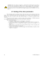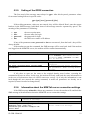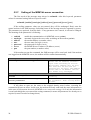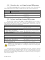
1
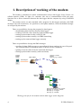
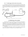
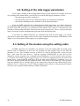
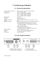
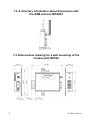
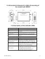
LP040
The GPRS modem for data loggers Sxxxx, Rxxxx
The instruction manual
Please read the instruction manual before the first device connection.
This version describes FW 1.0.1
Contents
1.
2.
3.
Description of working of the modem .........................................................................................4
General safety rules......................................................................................................................5
The modem and its accessories....................................................................................................7
3.1.
Accessories needed to operation ..........................................................................................7
•
The SIM card .......................................................................................................................7
•
The GSM antenna ................................................................................................................7
•
The electric power supply ....................................................................................................7
•
The COM adapter LP002 .....................................................................................................7
•
The data logger.....................................................................................................................8
•
The paid version of program for data loggers SWR001 ......................................................8
•
The M2MTalk server service...............................................................................................8
3.2.
Additional accessories..........................................................................................................8
•
The setting cable QMS2901.................................................................................................8
•
The self-adhesive Dual Lock MD036..................................................................................9
•
The modem wall holder MP036...........................................................................................9
•
The modem DIN rail 35mm holder MP037.........................................................................9
4. Quick installation .......................................................................................................................10
4.1.
Check of accessories ..........................................................................................................10
4.2.
Software installation ..........................................................................................................10
4.3.
The modem assembling .....................................................................................................10
4.3.1.
The SIM card .............................................................................................................10
4.3.2.
The GSM antenna ......................................................................................................11
4.3.3.
Connecting the power supply adapter........................................................................11
4.3.4.
The data logger and the modem interconnection .......................................................12
4.4.
Switching on the modem....................................................................................................12
4.5.
Setting up the modem ........................................................................................................13
4.5.1.
Setting of GPRS connection parameters....................................................................13
4.5.2.
Setting of M2MTalk client parameters ......................................................................13
4.6.
Login the modem on the M2MTalk server ........................................................................13
4.7.
Setting of the other parameters ..........................................................................................14
5. Communication via SMS messages...........................................................................................15
5.1.
The query SMS messages ..................................................................................................15
5.1.1.
The query about the current values ............................................................................15
5.1.2.
The query about the current values and their alarm limits.........................................16
5.1.3.
The query about the modem firmware version ..........................................................16
5.1.4.
The query about the current modem state information ..............................................17
5.2.
The statement SMS messages ............................................................................................17
5.2.1.
Login on the M2MTalk server ...................................................................................17
5.2.2.
Logout from the M2MTalk server .............................................................................17
5.2.3.
Restart of the modem .................................................................................................18
5.2.4.
Information about the GPRS connection settings ......................................................18
5.2.5.
Setting of the GPRS connection.................................................................................19
5.2.6.
Information about the M2MTalk server connection settings.....................................19
5.2.7.
Setting of the M2MTalk server connection ...............................................................20
5.2.8.
Information about permitting of the alarm SMS messages........................................21
5.2.9.
Setting of permitting of the alarm SMS messages .....................................................21
5.3.
The alarm SMS messages ..................................................................................................22
5.3.1.
The measured value exceeds the alarm limit .............................................................22
2
IE-GPR-LP040-02
5.3.2.
The data logger states.................................................................................................23
6. Settings of the program for data loggers to use it with the modem ...........................................24
6.1.
Settings of the communication with the modem and the modem parameters ...................24
6.2.
Setting of the data logger parameters.................................................................................30
6.3.
Setting of the modem using the setting cable ....................................................................30
7. Technical specification ..............................................................................................................31
7.1.
Technical parameters .........................................................................................................31
7.2.
The modem interface .........................................................................................................31
7.3.
A directory information about dimensions with the GSM antenna MP009/1 ...................32
7.4.
Dimensional drawing for a wall mounting of the modem with MP036 ............................32
7.5.
Dimensional drawing for a DIN rail mounting of the modem with MP037......................33
7.6.
Description of the indicator LEDs .....................................................................................33
7.7.
The list of the supported data logger types ........................................................................34
8. Technical support .......................................................................................................................34
9. Liquidation .................................................................................................................................34
IE-GPR-LP040-02
3
1. Description of working of the modem
The modem is intended for remote communication with a data logger Sxxxx, Rxxxx via
cellular network (GSM). In light of a customer, this way of communication offers the same
functions like a direct connection between the data logger and the computer by using COM/USB
adapter.
The modem can be set and controlled with a program for data loggers and also with SMS
messages (but with restrictions). It is possible to select phone numbers, from which SMS messages
are accepted by the modem.
These are possibilities of usage the program for data loggers:
• downloading data from the connected data logger
• reading of current values from the connected data logger
• setting up the modem locally via RS232 link
• setting up the modem remotely via GPRS networking
• setting up the connected data logger remotely
These are possibilities of usage the SMS messages:
• sending of alarm SMS messages to preconfigured phone numbers (in case of beyond
the set alarm limits for measured values or in case of error conditions)
• getting of current values from the connected data logger
• setting up the modem remotely (with restrictions)
Logger
Rxxxx/
Sxxxx
Current values
Alarms
Setting up a modem
GPRS modem
SMS
COM Adapter
M2M
GPRS
M2MTalk
Server
INTERNET
PC
PC
Downloading data from logger
Showing of current values
Setting up a logger
Setting up a modem
Working principle for the modem with the data logger (block diagram)
4
IE-GPR-LP040-02
2. General safety rules
The following summary describes a basic safety features related to device installation and
operation. Please read it properly before device installation. The following safety precautions must
be observed during all phases of the operation, usage, installation or repair of the device. Operate
the instrument in accordance with this manual to prevent damage of this device, damage of threeside devices or electric trauma.
Risk of electric shock
Do not use the instrument without the cover. Use only a safety adapter with
the power voltage recommended by device manufacturer. Before connecting,
check that the adapter has undamaged cables and cover. Do not use the
instrument, if it does not work correctly. If the instrument seems not to work
correctly, have it checked by a qualified service person.
Qualified service and installation
Service should be performed by a qualified person only. We recommend you
use only original accessories to avoid possible damage. When connecting to any
other device, read its user guide for detailed safety instructions. Do not connect
incompatible products. It is forbidden to connect other devices, while the
device is under electric voltage. If a damage of the device occurs due to gross
violation of these rules, a free guarantee repair will not have to be executed.
Usage in hospitals
When in a hospital or other health care facility, observe the restrictions on
the use of mobiles. Respect the directions and switch the cellular device off on
places, where using mobile phones is forbidden. Medical equipment may be
sensitive to RF energy.
Switch off in aircraft
Switch off the cellular device before boarding an aircraft. Make sure it cannot
be switched on inadvertently. The operation of wireless appliances in an aircraft is
forbidden to prevent interference with communications systems.
IE-GPR-LP040-02
5
Avoid fire and explosion
Do not use the instrument in an explosive environment. Do not operate
the cellular device in the presence of flammable gases or fumes. Switch off
the cellular device when you are near petrol stations, fuel depots, chemical
plants or where blasting operations are in progress. Operation of any
electrical equipment in potentially explosive atmospheres can constitute a
safety hazard.
Interference
Your cellular device receives and transmits radio frequency energy
while switched on. Remember that interference can occur if it is used close
to TV sets, radios, computers or inadequately shielded equipment. Always
switch off the cellular device wherever forbidden, or when you suspect that it
may cause interference or danger.
Service availability
Devices operate using radio signals and cellular networks. Because of
this, connection (SMS, GPRS, etc.) cannot be guaranteed at all times
under all conditions. Therefore, you should never rely solely upon any
wireless device for essential communications (emergency systems, safetyrelated systems). Remember, for hi-reliability systems is redundancy
necessary. For more information please see IEC 61508.
6
IE-GPR-LP040-02
3. The modem and its accessories
To use the entire facility, not only the modem, but proper accessories are also required.
3.1. Accessories needed to operation
• The SIM card
The SIM card is necessary for correct modem operation. It makes possible to send SMS
messages and to communicate with the data logger remotely via GPRS. In addition,
GPRS tariff must be activated for data transferring via GPRS. Method and amount of
payment for these services are determined by your mobile operator.
A PIN code entering must be deactivated on the SIM card. For more details see the
chapter The SIM card on page 10.
• The GSM antenna
The GSM antenna is also necessary for correct modem operation, the facility doesn’t
work without it. It must be mounted into antenna SMA connector. It is possible to use
the compact GSM antenna MP009/1 which is offered by the manufacturer. In case of
need, an external GSM antenna can be used.
• The electric power supply
The modem must be powered from an external power supply (a power supply adapter,
an accumulator battery). A power supply is connected to a supply terminal block. The
supply terminal block is a modem component. It is possible to use the power supply
adapter A1940 which is offered as optional equipment by the manufacturer.
• The COM adapter LP002
The adapter is intended for the data logger and the modem interconnection via RS232
serial link. This adapter provides a communication between the modem and the data
logger. The length of the cable is cca. 160 centimeters.
IE-GPR-LP040-02
7
• The data logger
The data logger is a target device. The modem is intended for communication with this
device. Generally, the data logger types Sxxxx and Rxxxx are supported. A complete list
of the supported devices can be found in the chapter The list of the supported data
logger types on page 34.
• The paid version of program for data loggers SWR001
This program makes possible to change of modem settings, to communicate with the
data logger, to read information about actual settings and data logger status, to change
parameters for data recording and to read measured data. Minimal program version must
be 2.1.7.0. The latest program versions are available on www.cometsystem.cz. A GPRS
connection or a setting cable (for example if the GPRS connection is not activated) can
be used for setting of the modem with this program.
• The M2MTalk server service
If you want use SMS messages only, you will not have to activate this service. For
anything else (like remote communication with the data logger including data
downloading), this service must be activated. By default, this service is already activated
by manufacturer. In addition, if this service is used, GPRS must be activated on your
SIM card. Method and amount of payment for this service are determined by valid
trading conditions.
3.2. Additional accessories
• The setting cable QMS2901
The cable is intended for setting of the modem with the program for data loggers (from
the computer) via RS232 serial link. It is needed for service purposes only, possibly for
local settings of the modem during its activation, for example if the GPRS connection is
not activated. Using of standard RS232 crossover cable as current computer equipment
is alternative variation. New computers are not equipped with serial COM port
generally. For solution of this problem, the converter MP006 (RS232/USB) is offered. It
is plugged between computer USB port and the setting cable. After installing included
driver, a virtual serial port in the computer is created for communication with the
instrument.
8
IE-GPR-LP040-02
• The self-adhesive Dual Lock MD036
The industrial hook-and-loop fastener for easy installation of the modem on a flat
surface.
• The modem wall holder MP036
The modem wall holder includes 2 screws for mounting on the back side of the modem
and set of 2 pieces of wall plugs + 2 pieces of screws for mounting on the wall.
• The modem DIN rail 35mm holder MP037
The modem DIN rail 35 mm holders include 4 screws for mounting on the back side of
the modem.
IE-GPR-LP040-02
9
4. Quick installation
4.1. Check of accessories
Make sure you have available all accessories needed to operation (the SIM card, the GSM
antenna, the power supply adapter, the COM adapter, the data logger, the pay version of program
for data loggers and access to the M2MTalk server service, if you want to use it).
4.2. Software installation
Install the paid version of program for data loggers (minimally the version 2.1.7.0) on the
computer, from what you want to have access to the device. The latest program version is available
on www.cometsystem.cz. Please follow instructions of the installer during installation process.
If you have activated a GPRS tariff, you will use the GPRS connection for setting of the
modem. In this case, installation of any others drivers is not needed.
If you want to set up the modem by using the setting cable via RS232 interface (for example
when you have not activated a GPRS tariff), you must also install driver for GPRS modem
configuration which is available on above web address too.
4.3. The modem assembling
4.3.1.
The SIM card
You must have activated a GPRS tariff if you want to communicate with the data logger
remotely via GPRS. A PIN code entering must be deactivated on the SIM card.
Using the SIM card in any mobile phone is the simplest method how to make sure that a PIN
code entering is deactivated. If a demand for entering a PIN code is displayed after switching the
mobile phone on, you will have to deactivate a PIN code entering. This procedure is dependent on a
type of the mobile phone and it should be described in a mobile phone’s user manual.
The SIM card is put in a holder. The holder is a modem component. The holder is ejected by
pressing the button beside the holder by using a fit instrument, for example a pencil. Insert the
prepared SIM card into the holder. See that the SIM card stays in alignment with the holder
correctly for all its size. After it, the holder with the inserted SIM card is pushed in the modem. The
correct way to install the SIM card is shown in the picture.
The way to install the SIM card
10
IE-GPR-LP040-02
4.3.2.
The GSM antenna
The GSM antenna must be mounted to the antenna connector by lightly tightening a sleeve
nut.
4.3.3.
Connecting the power supply adapter
The power supply adapter is connected on a WAGO terminal block which is a modem
component. Insert a flat-bladed screwdriver to rectangle terminal hole and push the screwdriver
towards away from you – the contact is released. Connect a wire to the released terminal and close
the terminal by removing the screwdriver. Connect positive pole of the terminal marked with + and
negative pole of the terminal marked with –. The correct way to connect wires is shown in the
pictures given below. In the case of using the power supply adapter A1940, connect the white wire
to positive pole and the black wire to negative pole.
Way to connect wires
The supply terminal block
The entire terminal block is possible to remove from the modem by pulling it up from the
connector.
IE-GPR-LP040-02
11
4.3.4.
The data logger and the modem interconnection
The data logger and the modem interconnection is provided with the COM adapter. Connect
the adapter connector to the RS232 connector on the modem and plug the adapter to the guide slots
on the side of the data logger. Heed to keep a minimum distance between the modem antenna and
the data logger during installation to prevent the data logger interference. This distance may not be
in any case less than 50 centimeters. Keeping the distance at least 1 meter is recommended. See the
picture.
The data logger, the modem and other accessories interconnection
4.4. Switching on the modem
The properly assembled modem is switched on by connecting the power supply adapter to
electrical power network. The green LED diode lights up. The modem will be prepared for
communication after cca. 1 minute from its switching on. It is advisable to check the
communication by sending SMS message gsmstatus to the modem phone number. A response
delivery time is generally dependent on a momentary cellular network load and state. If the modem
works correctly, it will send back SMS message with its state information. If you don’t receive the
response to this SMS message, please check your SIM card settings and your power supply adapter
and aerial connection.
If communication with the modem via cellular network is impossible, you can try to find a
problem with the program for data loggers. In this case, you must interconnect the modem and the
computer via the setting cable, see the chapter The setting cable QMS2901 on page 8.
12
IE-GPR-LP040-02
4.5. Setting up the modem
If you don’t intend to use remote communication with the data logger via GPRS, you can go
to the chapter Setting of the other parameters on page 14.
4.5.1.
Setting of GPRS connection parameters
If you didn’t specify the GPRS connection parameters before ordering the modem, you must
set it up now.
To do it, you can send a special SMS message to the modem phone number. The first word
of the message must always be gprs. After this keyword, parameter values for an actual setting
follows in specific order (see below):
gprs [apn] [user] [password] [dns]
If the trailing parameter values are not entered, they will be deleted. Don’t enter the square
brackets in the SMS message. Individual items of the message must be separated by spaces. For
more detailed information about setting this parameter values via SMS command see the chapter
Setting of the GPRS connection on page 19.
The example: You can set up the parameter apn to value internet without other parameters
(user, password and dns) by sending the SMS message
gprs internet
For getting information about GPRS connection parameters please contact an appropriate
mobile operator.
4.5.2.
Setting of M2MTalk client parameters
These parameters are already preset at the factory, don’t change it gratuitously! If you can
verify a setting, compare it with data listed in the card which was delivered with the modem.
M2MTalk client parameters can be set via the SMS command (see the chapter Setting of the
M2MTalk server connection on page 20) or via the setting cable (see the chapter Setting of the
modem using the setting cable on page 30).
4.6. Login the modem on the M2MTalk server
If you intend to use remote communication with the modem or data logger via GPRS (for
example to set up this device remotely), the modem always must be logged on the M2Mtalk server
before starting the communication. The modem can be set up to login on the server automatically
after its switching on, but it isn’t a standard factory setting.
To login the modem on the M2MTalk server, you can send a SMS message login to the
modem phone number. The modem will send back an acknowledge SMS message. It is advisable to
check the login status by sending SMS message gsmstatus to the modem phone number. If the
modem works correctly, it will send back SMS message with information. The login status is also
including in these information (M2MTalk online: yes).
IE-GPR-LP040-02
13
Attention! Since the modem is logged on, a limited data transferring also proceeds in
case the remote communication with the device isn’t in progress (due to keeping the
connection). Transferred data is charged as per your GPRS tariff by the mobile operator.
Logout from the server is described in the chapter Logout from the M2MTalk server on
page 17.
4.7. Setting of the other parameters
The information about exceeding of alarm limits and about correct operation of the data
logger can be periodically taken from the data logger by the modem. These information are
processed and then the modem sends alarm SMS messages to a customer according to these
analyses.
The program for data loggers is used for setting of these parameters. If GPRS connection
isn‘t activated, you will have to set up the modem by using the setting cable.
There are these parameters:
• data logger reading interval, see the chapter 6.1 on page 24
• sending / no sending of the warning SMS messages, see the chapter 6.1 on page 24
• phone numbers for the warning SMS messages recipients, see the chapter 6.1 on
page 24
• phone numbers, from which the incoming SMS messages will be accepted by the
modem, see the chapter 6.1 on page 24
• setting of the alarm limits for the data logger if this functionality is required, see the
chapter 6.2 on page 30
14
IE-GPR-LP040-02
5. Communication via SMS messages
It is possible to control and monitor the device operation remotely via the special SMS
messages, which are being sent to the modem phone number. The user can select phone numbers,
from which the SMS messages are accepted by the modem. The factory configuration doesn’t
restrict the phone numbers for any incoming SMS messages that means any SMS messages are
accepted regardless of the sender phone number. Phone numbers restriction can be done with the
program for data loggers, see the chapter Settings of the program for data loggers to use it with the
modem on page 24.
Generally, SMS command messages aren’t case sensitive and the space serves as a
parameter separator.
If the accepted command isn’t supported or it hasn’t a correct syntax or parameters, the
modem will send back an SMS message with a proper error description. This information will be
returned only three times in maximum. The fourth and every next incorrect command from the one
phone number is ignored until the incoming command will be correct again.
5.1. The query SMS messages
Using these messages, you can take the current measured values from the connected data
logger, the modem firmware version and the current modem state information.
5.1.1.
The query about the current values
To take the current measured values from the connected data logger, send the SMS message
values to the modem. The modem will send back a SMS message with the following contents:
• data logger identification – the user’s description of the data logger is displayed. If
this description isn’t set, the serial number of the data logger will be displayed. If the
total message length would exceed 160 characters, the serial number of the data logger
will be displayed instead of the description.
• measured values of single quantities – the channel number or channel description (if it
is set) is displayed, the measured value and the quantity unit follow. If the measured
value exceeds any alarm limit, the symbol „!“ will be displayed in front of the value.
The response message example:
Logger Store_13: Temp: 24.7C Hum: 45.5%RH DP: !12.1C
If it is not possible to take information about the measured values, i.e. the data logger is
switched off or a communication error between the modem and the data logger has occurred, the
modem will send back a SMS message with a proper error description.
IE-GPR-LP040-02
15
The command
values
The command for reading of the current values.
An example of the response message
Logger Store_13: Temp: 24.7C Hum: 45.5%RH The current values from the data
DP: !12.1C
logger.
The logger is switched off
An error occurred during communication
with the logger
5.1.2.
A query can’t be processed, because
the data logger is switched off.
A query can’t be processed, because
a communication error between the
modem and the data logger has
occurred.
The query about the current values and their alarm limits
To take the current measured values from the connected data logger and their alarm limits,
send the SMS message values! to the modem. The content of the response message is the same with
a query values. In addition, this response message includes their alarm limits in this case.
The response message example:
Logger Store_13: Temp: 24.7C 19.0..26.0 Hum: 45.5%RH 0.0..50.0 DP: !12.1C 0.0..10.0
The command
values!
The command for reading of the current values and their alarm
limits.
An example of the response message
Example 1:
The current values and their alarm
#12345678: #1: 24.7C 19.0..26.0 #2:
limits from the data logger.
45.5%RH 0.0..50.0 #6: !12.1C 0.0..10.0
Example 2:
Logger Store_13: Temp: 24.7C 19.0..26.0
Hum: 45.5%RH 0.0..50.0 DP: !12.1C
0.0..10.0
The logger is switched off
A query can’t be processed, because
the data logger is switched off.
An error occurred during communication
A query can’t be processed, because
with the logger
a communication error between the
modem and the data logger has
occurred.
5.1.3.
The query about the modem firmware version
To take the modem firmware version, send the SMS message firmware to the modem.
The command
Firmware
The command for reading of the modem firmware version.
An example of the response message
Datalogger Communicator v. 1.1.0
16
The modem firmware version.
IE-GPR-LP040-02
5.1.4.
The query about the current modem state information
To take the current modem state information, send the SMS message gsmstatus to the
modem. The modem will send back a SMS message with followed information:
The command
gsmstatus
The command for reading of the current modem state information.
An example of the response message
Uptime: 0d 0hr 26min;M2MTalk online:
Elapsed time from the modem‘s
yes;Operator: "T-Mobile CZ","T-Mobile
switching on.
CZ";RSSI: 66dbm;Signal: 99;Registered on
The current M2MTalk server login
network: yes;Roaming: no
status.
The name of GSM operator.
The signal strength [dBm].
The signal quality.
The SIM card registration on the
cellular network (GSM).
The SIM card registration on the
foreign network (it says if the
roaming is active).
5.2. The statement SMS messages
Using these messages, you can control and set up the modem remotely.
5.2.1.
Login on the M2MTalk server
If you intend to use remote communication with the modem or data logger via GPRS (for
example to set up this device remotely), the modem always must be logged on the M2Mtalk server
before starting the communication. The modem can be set up to login on the server automatically
after its switching on, but it isn’t a standard factory setting.
To login the modem on the M2MTalk server, you can send a SMS message login to the
modem phone number. The modem will send back an acknowledge SMS message.
The command
login
The command for login on the M2MTalk server.
The response message
The demand for login on the server was
Information about acceptance of
accepted
demand for login on the M2MTalk
server.
This module is already logged on the
The message – the modem was already
server
logged on the M2MTalk server.
5.2.2.
Logout from the M2MTalk server
Since the modem is logged on, a limited data transferring also proceeds in case the remote
communication with the device isn’t in progress (due to keeping the connection). Transferred data
is charged as per your GPRS tariff by the mobile operator. If you intend to use remote
communication via GPRS no longer, you can logout the modem from the M2MTalk server to
reduce transferred data.
IE-GPR-LP040-02
17
The command
logout
The command for logout from the M2MTalk server.
The response message
The demand for logout on the server was
Information about acceptance of
accepted
demand for logout from the M2MTalk
server.
This module is not logged on the server
The message – the modem wasn‘t
logged on the M2MTalk server.
5.2.3.
Restart of the modem
This command is intended for the remote restart of the modem, for example in the event of
the problem with GPRS connection. The complete restart of the modem takes about 2 minutes.
The command
restart
The command for restart of the modem.
The response message
The demand for application restart was
Information about acceptance of
accepted
demand for restart of the modem.
5.2.4.
Information about the GPRS connection settings
If the SMS message gprs without any parameters is sent, the modem will send back the
SMS message with information about the current GPRS connection settings.
The command
gprs
The command for reading of information about the GPRS connection
settings.
An example of the response message
APN='internet' User='' Password='' DNS='' Information about the GPRS
connection settings.
18
IE-GPR-LP040-02
5.2.5.
Setting of the GPRS connection
The first word of the message must always be gprs. After this keyword, parameter values
for an actual setting follows in specific order:
gprs [apn] [user] [password] [dns]
If the trailing parameter values are not entered, they will be deleted. Don’t enter the square
brackets in the SMS message. Individual items of the message must be separated by spaces. The
meaning of the parameters is following:
•
•
•
•
apn
user
password
dns
the access point name
the user name for login
the password for login
the DNS server name or IP address
If any of the parameters user, password or dns are not entered „from the back“, they will be
always deleted.
If the modem accepts the command, the SMS message will be sent back. And if the modem
was logged on the M2MTalk server, the modem will be restarted automatically.
An example of the command with parameters
gprs internet
The response message
GPRS parameters were set and stored
An error occurred while setting GPRS
parameters
Setting of the parameter apn to the
value internet. The values of the
parameters user, password and dns
will be deleted.
All parameters were set and stored
correctly.
An error occurred during setting
the parameters. Their saving didn’t
succeed.
If all values to store are the same as the original already stored values, executing the
command will have no effect. In this case, the modem will only send back the same information as
in the case of Information about the GPRS connection settings. So if only the information is sent
back though the user entered the setting command, it means all parameters are already set as
required (it wasn’t needed to change them).
5.2.6.
Information about the M2MTalk server connection settings
If the SMS message m2mtalk without any parameters is sent, the modem will send back the
SMS message with information about the M2MTalk server connection settings.
The command
m2mtalk
The command for reading of information about the M2MTalk server
connection settings.
An example of the response message
Enabled='yes' Autologin='yes'
Information about the M2MTalk
Address='1234' User='usr'
server connection settings.
Password='psw'Server='example.com'
Port='9999'
IE-GPR-LP040-02
19
5.2.7.
Setting of the M2MTalk server connection
The first word of the message must always be m2mtalk. After this keyword, parameter
values for an actual setting follows in specific order:
m2mtalk [enabled] [autologin] [address] [user] [password] [server] [port]
If the trailing parameter values are not entered, they will be unchanged. Don’t enter the
square brackets in the SMS message. Individual items of the message must be separated by spaces.
The parameters are optional „from the back“. If any parameter isn’t entered, it will not be changed.
The meaning of the parameters is following:
•
•
•
•
•
•
•
enabled
autologin
address
user
password
server
port
enable the communication via M2MTalk server (yes/no)
automatic login on the server after switching on the modem (yes/no)
the modem address (a number value)
the user name for login (a text)
the password for login (a text)
the M2MTalk server name or IP address (a text)
the port number (a number value)
If the modem accepts the command, the SMS message will be sent back. And if the modem
was logged on the M2MTalk server, the modem will be restarted automatically.
An example of the command with parameters
m2mtalk yes no 2006 2006 mypsw
The response message
M2MTalk server parameters were set and
stored
An error occurred while setting M2MTalk
server parameters
The communication via M2MTalk
server will be enabled, automatic
login after switching on will be
deactivated, address will be 2006,
user name will be 2006 and the
password will be mypsw. The M2MTalk
server name or IP address and the
port number stay unchanged.
All parameters were set and stored
correctly.
An error occurred during setting
the parameters. Their saving didn’t
succeed.
If all values to store are the same as the original already stored values, executing the
command will have no effect. In this case, the modem will only send back the same information as
in the case of Information about the M2MTalk server connection settings. So if only the information
is sent back though the user entered the setting command, it means all parameters are already set as
required (it wasn’t needed to change them).
20
IE-GPR-LP040-02
5.2.8.
Information about permitting of the alarm SMS messages
If the SMS message alarms without any parameters is sent, the modem will send back the
SMS message with information whether sending of the alarm SMS messages is enabled or not.
The command
alarms
The command for reading of information about permitting of the
alarm SMS messages.
The possible response messages
Sending of warning messages is switched
Sending of the alarm SMS messages
on
is enabled.
Sending of warning messages is switched
Sending of the alarm SMS messages
off
is disabled.
5.2.9.
Setting of permitting of the alarm SMS messages
The syntax of this command is either alarms on or alarms off. In the first case, sending of
the alarm SMS messages will be enabled. Alarm states will be checked periodically. If any alarm
occurs, the alarm SMS message will be sent to the predefined phone numbers. In the second case,
sending of the alarm SMS messages will be disabled.
The command
alarms on
An example of the response message
Sending of warning messages was switched
on from number +420123456789
An error occurred while switching sending
of warning messages on
The command
alarms off
An example of the response message
Sending of warning messages was switched
off from number +420123456789
An error occurred while switching sending
of warning messages off
Sending of the alarm SMS messages
will be enabled.
Sending of the alarm SMS messages
was enabled from the phone number
+420123456789.
The error occurred, saving of the
parameter didn’t succeed.
Sending of the alarm SMS messages
will be disabled.
Sending of the alarm SMS messages
was disabled from the phone number
+420123456789.
The error occurred, saving of the
parameter didn’t succeed.
Attention! If this setting is performed successfully, the response message will be sent
not only to sender’s phone number, but also to all phone numbers for the warning SMS
messages recipients!
If the value to store is the same as the original already stored value, executing the command
will have no effect. In this case, the modem will only send back the same information as in the case
of Information about permitting of the alarm SMS messages. So if only the information is sent back
though the user entered the setting command, it means the parameter is already set as required (it
wasn’t needed to change it).
IE-GPR-LP040-02
21
5.3. The alarm SMS messages
These messages are being sent to the predefined phone numbers independently of the user
(see the chapter Settings of the communication with the modem and the modem parameters on page
24). The information about exceeding of alarm limits and about correct operation of the data logger
can be periodically taken from the data logger by the modem. Concretely, following data logger
states are monitored:
• the measured value exceeds the alarm limit (the alarm is active)
• communication error
• the data logger state (switched on / off)
• the data logger real time clock error
• the data logger memory is 90% full
• the data logger memory is full
• the expected data logger battery life expired
• the data logger battery voltage is too low
If GPRS connection isn‘t activated, you will have to set up the alarm SMS messages
parameters by using the setting cable. Following parameters must be set with the program for data
loggers:
• data logger reading interval
• sending / no sending of the warning SMS messages
• phone numbers for the warning SMS messages recipients
5.3.1.
The measured value exceeds the alarm limit
Exceeding of the alarm limit is evaluated by the data logger. To work it correctly, following
parameters must be set for the data logger:
• the data logger must be switched on
• the alarm limits must be set with desired means for all monitored quantities
• the alarm evaluating must be enabled for all monitored quantities
The incoming SMS message begins with the user’s description of the data logger. If the
description isn’t set for the data logger, the serial number of the data logger will be displayed. If the
total message length would exceed 160 characters, the serial number of the data logger will be
displayed instead of the description. The symbol „!“ is displayed in front of the value which
exceeds any alarm limit.
The incoming alarm SMS message
Example 1:
#12345678: #1: 24.7C 19.0..26.0 #2:
45.5%RH 0.0..50.0 #6: !12.1C 0.0..10.0
Example 2:
Logger Store_13: T: 24.7C 19.0..26.0 RH:
45.5%RH 0.0..50.0 DP: !12.1C 0.0..10.0
22
The current values and their alarm
limits from the data logger.
IE-GPR-LP040-02
5.3.2.
The data logger states
Communication error
The incoming alarm SMS message
An error occurred during communication
with the logger
An error occurred while
communication between the modem and
the data logger.
The data logger state (switched on / off)
The incoming alarm SMS message
The logger is switched off
The data logger is switched off.
The incoming alarm SMS message
The logger is switched on
The data logger is switched on.
The data logger real time clock error
The incoming alarm SMS message
The logger real time clock error
The data logger real time clock
isn’t adjusted correctly.
The data logger memory is 90% full
The incoming alarm SMS message
The logger memory is 90% full
The data logger memory is 90% full.
The data logger memory is full
The incoming alarm SMS message
The logger memory is full
The data logger memory is full.
The expected data logger battery life expired
The incoming alarm SMS message
The end of the expected logger battery
life
The expected data logger battery
life expired.
The data logger battery voltage is too low
The incoming alarm SMS message
The logger power supply is low
IE-GPR-LP040-02
The data logger battery voltage is
too low.
23
6. Settings of the program for data loggers to
use it with the modem
Attention! If GPRS connection isn’t available, you will have to use the setting cable. Move
ahead the chapter Setting of the modem using the setting cable on page 30.
All following parameter settings are mentioned for an information only, the correct values
must be entered everywhere!
6.1. Settings of the communication with the modem
and the modem parameters
Run the program for data loggers. Select the item File / Options in the main menu. In the
window Options, select the item M2M connection on the left bar first. A following window will be
displayed.
The items Server and Port are already pre-filled, don’t change it gratuitously! Fill the items
PC’s M2M address a M2M login password with data listed in the card which was delivered with the
modem. Confirm these settings with pressing Apply button.
Further, in the window Options, select the item Communication on the left bar. A following
window will be displayed.
24
IE-GPR-LP040-02
Select the item Select port manually and press the button List of ports.... The window List of
communication ports will be displayed.
In this window, press the button Add port. The window Add communication port will be
displayed.
IE-GPR-LP040-02
25
Select the item GPRS (M2M modem) here and then press the button Next >.
The window M2M port properties will be displayed. Set the connection parameters for the
modem here. The item Name is intended for user’s description of connection, choose your own
name. Fill the item Address with data listed in the card which was delivered with the modem. If you
want to prevent unauthorized access to your modem (data logger), you will have to fill the item
Secure communication key with your entered password. Remember this password well, it will have
to be entered during setting of the modem later!
Continue with pressing Modem configuration button. Communication with the modem
begins. If all previous settings are correct, a following window will be displayed. If not, please
check the settings described in the chapter Settings of the communication with the modem and the
modem parameters on page 24.
26
IE-GPR-LP040-02
In this window, enter Security communication key according to setting in the window M2M
port properties on page 26. If you require the modem’s login on the server automatically after its
switching on (so that GPRS communication can be available), you will have to tick off the field
Auto login to M2M server. Don’t change other parameters in this window gratuitously, it can cause
problem with communication!
After pressing Next >> button, the window for settings of phone numbers restriction for
communication via SMS messages will be displayed.
IE-GPR-LP040-02
27
Communication via SMS messages can be restricted to selected phone numbers only. If no
phone numbers are in the list, the modem will process the incoming SMS messages from all phone
numbers. If you add some phone numbers to this list, the modem will process the incoming SMS
messages only from these selected phone numbers.
After pressing Add button, enter the phone numbers from which you want to send SMS
command messages to the modem. All phone numbers must have the international format (for
example +420123456789).
After pressing Next >> button, the window for settings of the alarm SMS messages
parameters will be displayed.
28
IE-GPR-LP040-02
The information about exceeding of alarm limits and about correct operation of the data
logger can be periodically taken (according to the item Check alarm status) from the data logger by
the modem. These information are processed and then the modem sends alarm SMS messages to a
customer according to these analyses. If you require sending of the warning SMS messages by the
modem, you will have to tick off the field Send warning SMS and enter the phone numbers for the
warning SMS messages recipients.
After pressing Apply button, all settings are stored into the modem and then the modem will
be restarted. Confirm all opened windows with pressing OK button.
IE-GPR-LP040-02
29
6.2. Setting of the data logger parameters
If you require sending of the warning SMS messages by the modem (for example in the case
of exceeding of the alarm limits), you will have to set these data logger parameters at least:
• the data logger must be switched on
• the alarm limits must be set with desired means for all monitored quantities
• the alarm evaluating must be enabled for all monitored quantities
If you use GPRS connection for communication with the data logger, you will be allowed to
set up the data logger remotely by using the program for data loggers. For the remote connection
you must select the item Select port manually in the window File / Options / Communication and
confirm it with pressing OK button. Then select the item Configuration / Device setting in the main
menu. Choose the correct communication port name from the displayed list.
If you don’t use GPRS connection for communication with the data logger, you will be
allowed to set up the data logger locally via the proper communication adapter (COM adapter, USB
adapter). Use the program for data loggers to set up data logger.
6.3. Setting of the modem using the setting cable
If GPRS connection isn’t available, you will have to use the setting cable for setting up the
modem with no limitations. In this case, the program for data loggers must be run with the
parameter /service. The available way how to achieve it: click on the button Start, select the item
Run..., then select the item Browse..., find the program LOGGER.EXE in your drive (if the
destination of this program wasn’t changed during installation, it will be placed in the directory
C:\Program Files\CometLoggers\Logger\Logger.exe), select it by using the mouse and click on the
button Open. In the displayed field Open, write the char space followed by parameter /service at
the end of displayed path (past the quotation mark). Then click on the button OK. After program
start, the submenu Service should appear in the main menu. Select the item M2M modem in the
submenu Service. Choose the correct COM port number and confirm it with pressing OK button.
Now you can set up all modem parameters with no limitations.
30
IE-GPR-LP040-02
7. Technical specification
7.1. Technical parameters
Communication with the device:
Frequency band:
Output power:
SIM card type:
GPRS class:
Antenna:
Supply terminal block:
IP code:
Operating conditions:
Storage conditions:
Dimensions:
Weight:
Box material:
RS232 (connector Canon 9) for the COM adapter
850/900/1800/1900 MHz
Class 4 (+33dBm ±2dB) for EGSM850
Class 4 (+33dBm ±2dB) for EGSM900
Class 1 (+30dBm ±2dB) for GSM1800
Class 1 (+30dBm ±2dB) for GSM1900
1,8V or 3V
multislot class 12
50 ohm, SMA connector
removable, WAGO 734, max. size of conductors 1.5 mm2
IP30
The power supply: external 9-32V DC, peak input up to 10W
The operating temperature range: from -30°C to +65°C
External characteristics determination by EN33-2000-3:
Environment standard as per NM with these corrections:
AE1, AN1, AR1, BE1
Operating position: arbitrary
Device mounting (optional equipment):
self-adhesive Dual Lock, wall holder, DIN rail holder
temperature from -40°C to +85°C
105 x 71 x 24mm (without antenna and holders)
cca 180g (without antenna and holders)
anodized aluminum
7.2. The modem interface
1 = RS232 connector, 9 pin, male
2 = SIM card holder and connector
3 = antenna connector, SMA, female
IE-GPR-LP040-02
4 = yellow indicator LED
5 = green indicator LED
6 = supply terminal block, WAGO
31
7.3. A directory information about dimensions with
the GSM antenna MP009/1
7.4. Dimensional drawing for a wall mounting of the
modem with MP036
32
IE-GPR-LP040-02
7.5. Dimensional drawing for a DIN rail mounting of
the modem with MP037
7.6. Description of the indicator LEDs
The green indicator LED
does not light
lights
The reason
the modem isn‘t connected to a power supply
the modem power supply is on, this is a correct
operation
switches off for a short time
a checking signal, this is a correct operation
(every cca 30s)
the modem is restarting (restart takes about 1
blinks
minute)
The yellow indicator LED The reason
does not light
a GSM part is switched off
the modem is successfully connected via the
blinks one time for a short
cellular network (GSM), i.e. the modem replies
time every cca 3s
for the SMS messages, GPRS isn‘t connected
blinks two times for a short GPRS connection is active, i.e. it is possible to
time every cca 3s
communicate with the data logger remotely, the
modem replies for the SMS messages
- the SIM card is not inserted
- a PIN code isn’t deactivated on the SIM card
- the GSM antenna isn’t mounted
blinks regularly
- searching for the network is in progress
- login to the network is in progress
IE-GPR-LP040-02
33
7.7. The list of the supported data logger types
Firmware version The supported data logger types
R0110, R0111, R0121, R0122, R0141, R0841, R3120, R3631,
R3541, R6011, R6021, R5011, R5021, R3121, R0110E
1.0.0
1.0.1
S0110, S0111, S0121, S0122, S0141, S0841, S3120, S3631,
S3541, S6011, S6011, S6021, S6021, S5011, S5011, S5021,
S5021, S3121, S7021, S0541, S0442, S3532, S7841, S0842,
S0110E, S0110F, S0111F
8. Technical support
Technical support is provided by a distributor of this device. The contact is presented in the
included warranty certificate. In case of need, you can also make use of a discussion forum on
http://www.forum.cometsystem.cz/.
A short description of the discussion forum is on http://www.cometsystem.cz/forum.htm.
9. Liquidation
The device must be liquidated ecologically after its disconnecting!
34
IE-GPR-LP040-02