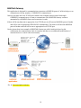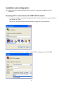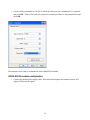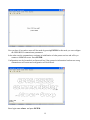
1
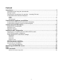
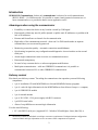
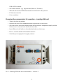
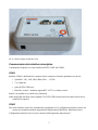
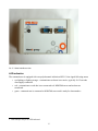
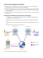
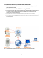
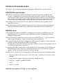
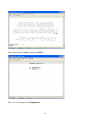
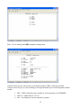
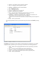
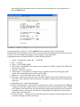
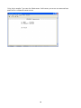
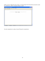
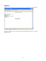
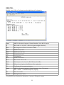
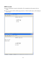
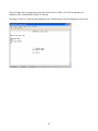
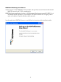
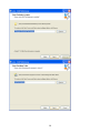
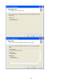
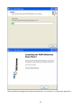
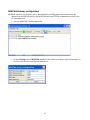
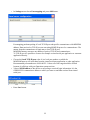
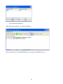
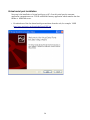
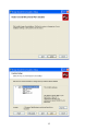
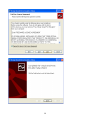
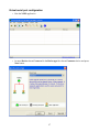
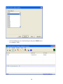
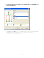
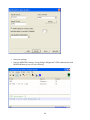
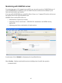
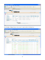
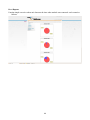
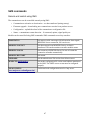
GPRS-RS232 Communicator
user guide
Content
Introduction...............................................................................................................................3
Advantages when using the communicator.......................................................................................3
Delivery content ...............................................................................................................................3
Preparing the communicator for operation – inserting SIM card........................................................4
Communicator data interface description..........................................................................................6
COM1...........................................................................................................................................................6
COM2...........................................................................................................................................................6
LED indication..............................................................................................................................................7
Communicator appliance possibilities...................................................................................8
Communicator GMS tunnel mode function description......................................................................8
Communicator Multipoint function mode description.........................................................................9
Solution technical description...............................................................................................10
GPRS-RS232 communicator..........................................................................................................10
M2MTalk server..............................................................................................................................10
M2MTalk Gateway..........................................................................................................................10
Installation and configuration ...............................................................................................13
Preparing PC to communicate with GPRS-RS232 module .............................................................13
GPRS-RS232 module configuration................................................................................................14
Other GPRSRS232 communicator settings.....................................................................................22
Diagnostics.................................................................................................................................................22
GSM INFO .................................................................................................................................................23
GSM CELL.................................................................................................................................................24
RS232 console...........................................................................................................................................25
M2MTalk Gateway installation.........................................................................................................28
M2MTalkGateway configuration......................................................................................................32
Virtual serial port installation...........................................................................................................35
Virtual serial port configuration...................................................................................................................38
Monitoring with M2MTalk server...........................................................................................43
FAQ:..........................................................................................................................................46
SMS commands......................................................................................................................48
Remote unit control using SMS .................................................................................................................48
1
Introduction
GPRS-RS232 Communicator, further only communicator is a device for serial communication
(RS232, RS485 ...) in GSM networks. It is possible to create virtual connection between two or
more communicators or to provide the data to a user application on PC.
Advantages when using the communicator
•
Possibility to connect the device at any location covered by GSM signal
•
Data transfer without any need of public dynamic or public static IP addresses, no problem with
lack of IP addresses
•
Routers and firewalls are no obstacle for the communication
•
High safety of the communicator network – there can´t be DOS attacks made on separate
communicators, access secured by password
•
Monitoring connection quality – automatic connection reestablishment
•
Quick setting in operation, easy configuration and diagnostics via text interface on the second
serial port
•
Actual single communicator state overview on communication server
•
Data transfer transparency
•
No need of any customer device or software equipment modifications
•
Multi-point communication – with one GPRSRS232 communicator it is possible to
communicate from more PCs or other GPRSRS232 communicators
Delivery content
First check your delivery content.* For taking the communicator into operation you need following
components:
•
1pc of installation CD with M2MTalkServer Lite and M2MTalkGateway programs
•
1pc of card with login information for the M2MTalkServer from Alarex-Group s.r.o. company
•
1pc of GPRS-RS232 module
•
1pc of external antenna
•
1pc of DC 8-58V, 15 W power supply with RJ12 connector
•
1pc RS232 serial cable
•
Alarex Group M2M server account login information
You also need following:
•
*
PC with RS232 serial port (supported OS – Windows XP and higher, Linux, Mac OS) or
The delivery content is individual according to customers requirements. Package minimum configuration
contains module and login information to user accounts. Other components are optional.
2
USB->RS232 converter
•
SW terminal emulator (e.g. Hyperterminal, Minicom, Terraterm)
•
SIM card with activated GPRS data transfer and switched off PIN protection
•
PC Internet connection
•
Cross screwdriver
Preparing the communicator for operation – inserting SIM card
•
Take the box from the package.
•
Open the side door of the communication unit to gain access to cross screws.
•
Screw out all four screws and carefully detach the lid. Attention! Manipulate carefully with the
lid because it is connected to the board with data cables.
•
Insert SIM card to the holder on the motherboard and screw the box up.
•
Put on – screw the antenna to the antenna connector
•
Switch the power supply into the supply connector
Pic. 1: Inserting SIM card into communicator – view no.1
3
Pic. 2: Inserting SIM card into communicator – view no.2
Pic. 3: Antenna connector view
4
Pic. 4: Power supply connector view
Communicator data interface description
Communicator disposes two serial interfaces RS232 COM1 and COM2.
COM1
Interface COM1 is dedicated for customer device connection. Interface parameters can be set:
•
Speed Bd – 300, 1200, 2400, 4800, 9600 … 115200
•
7 or 8 data bits
•
parity EVEN, ODD, non
•
Data flow control – hardware signals RTC a CTS, or without control
further it is possible to set buffer size, time delay.
When using HW data flow control signals CTS, RTS, DTR are used and serial cable with all wires
connected is required.
COM2
This serial interface is used for communicator configuration. For configuration interface control you
can use any terminal emulation program like Hyperterminal (Windows), Minicom (Linux) .
Configuration interface is text, access is secured with login name and password.
5
Pic. 5: Data interfaces view
LED indication
The communicator is equipped with one polychromatic indication LED. Colors signal following states:
•
not lighting or lighting orange – communicator software is not active, typically 10-15 seconds
after supply connection
•
red – communicator works but is not connected to k M2MTalk server and no data are
transferred
•
green – communicator is connected to M2MTalk server and is ready for data transfer. *
* Data transfer itself is not LED indicated.
6
Communicator appliance possibilities
Next chapter describes two possible modes of communicator application. First mode (GSM tunnel)
allows connection of two RS232 devices using two communicators.
Second mode (Multi-point) allows to create a network of more mutually interconnected communicators
with one or more PC applications. More detailed description including specific setting is described
in following chapters.
Data transfer in both modes is fully transparent and does not require any device or software equipment
modifications.
Communicator GMS tunnel mode function description
•
Communicator no.1 converts data coming from serial line to M2MTalk protocol and sends it
over GSM network to M2MTalk Server.
•
M2MTalk Server provides data packets routing. In this case direct resending to communicator
no.2.
•
Communicator no.2 converts data coming from GSM network from M2MTalk protocol to serial
line.
•
Data transfer in opposite direction goes the same way.
Pic. 6: Communication between two GPRS-RS232 communicators
7
Communicator Multi-point function mode description
•
Customer device is connected to the communicator via serial interface using standard serial
cable transferring all signals.
•
Communicators are connected to M2MTalk Server using GSM/GPRS.
•
M2MTalk Server routes data packets. Depending on the way of appliance and application logic
of customer´s solution it can be routing between communicators or routing between any
communicator and customer application.
•
User application is connected with M2MTalk Server using M2M Gateway interface.
•
M2M Gateway is a software application installed on PC that converts data from M2M protocol
to TCP/IP protocol.
Pic. 7: User application communication with one or more GPRS-RS232 communicators
8
Solution technical description
This chapter contains principals and technical description of HW and SW component function.
GPRS-RS232 communicator
GPRS-RS232 communicator transfers communication between GSM network and RS232 serial
interface. Communication received from GSM network is stored in a buffer and later sent to
serial interface. Buffer mechanism strictly keeps data packet divided as it was received from
GSM network. It also pairs requests (GSM data) and answers (serial port data) so that it is
ensured that more subscribers can communicate with the customer device at one time.
Data coming from serial interface RS232 are is stored in second buffer and are gradually sent to
appropriate receivers.
Serial communication is fully transparent. Customer devices or customer software does not need to
implement M2MTalk transfer protocol, there are no modifications needed on customer side.
M2MTalk server
GSM communication between GPRSRS232 communicators is executed via M2MTalk server with
M2MTalk protocol. You can easily imagine M2MTalk server like ICQ designed for different
machines communication.
Everyone who wants to communicate with any server user (GPRS-RS232, PC ..) logs in to the server
under a unique ID (address). Login is secured by user name and password.
After successful login user can start to communicate with other devices logged in to server using data
messages. It can be transferred up to 40KB in one message.
Message queue system assures that data from sender is taken to process as fast as possible and wait
on the server for the receiver to process it.
To speed up GSM/GPRS communication, single members do not acknowledge received messages on
M2MTalk protocol level. Only in case that M2MTalk server does not see particular logged on
member (on-line), it answers the sender with an error message.
M2MTalk server is written in JAVA language and is fully functional on most used operation systems.
•
Microsoft Windows XP, Server 2003, Server 2008, Vista – is installed as an operation system
“service”
•
Linux – Debian, RedHat, CentOs, Suse, Mandriva, Ubuntu and other
•
BSD Unix – FreeBSD, OpenBSD, NetBSD ..
•
Solaris
•
MacOs – not tested
M2MTalk server requires JAVA JRE 1.6.x for its operation
9
M2MTalk Gateway
This application is designed for communication conversion to M2MTalk protocol. With its help we can
communicate with any number of GPRSRS232 communicators.
After its start there are local TCP/IP ports created in the computer that are paired with single
GPRSRS232 communicators we want to communicate with. M2MTalk Gateway connects
automatically to M2MTalk Server and connection is ready.
If there will be any data sent to appropriate local TCP/IP port it will have an M2MTalk protocol header
and will be sent to appropriate GPRS-RS232 communicator. The answer will have the M2MTalk
protocol header removed will be sent to appropriate local TCP/IP port.
On the picture there is an example of M2MTalk Gateway use with virtual serial port. In this
combination the communication chain is complete and there are no additional modifications of
customer device or control software necessary.
Pic. 8: Communication schema
10
Installation and configuration
This chapter describes single installation steps necessary for setting and configuration of SW
components.
Preparing PC to communicate with GPRS-RS232 module
•
Connect PC with the communicator using serial cable. On the module side connect the cable to
port marked as COM2.
•
Start the PC and open any data terminal emulation program (e.g. Hyperterminal)
•
Set in the connection name, for example “GPRS-RS232 configuration” and click OK.
11
•
Choose serial port number of your PC to which the cable from the communicator is connected
and click OK. Then set the serial port properties according to values on the picture bellow and
click OK.
The terminal is now ready to communicate with GPRS-RS232 module.
GPRS-RS232 module configuration
•
Connect the module power supply cable. After the initial sequence the terminal window will
display Off-line mode request.
12
Now you have 10 seconds to enter off-line mode by pressing ENTER. In this mode you can configure
the GPRS-RS232 communicator parameters.
In the other case the communicator continues in initialization of other preset services and will try to
connect to M2MTalk server. Press ENTER.
Configuration can also be made in on-line mode but if the connection information has been set wrong
communicator will restart and configuration will be difficult.
Enter login name: alarex and press ENTER.
13
Enter login password: alarex and press ENTER.
Press <1> for entering menu Configuration.
14
Press <1> for entering the GPRS parameter setting screen.
Values for choices (1) to (5) are set by your mobile operator, GPRS connection provider.
Values for choices (6) to (C) set according to the login information you received together with the
module.
1. APN – GPRS connection point, actually by Czech operators it is INTERNET
2. Timeout – GPRS timeout - 30-120
3. User – not obligatory, may be required by operator
15
4. Password - not obligatory, may be required by operator
5. DNS - not obligatory, may be required by operator
6. M2MServ. - M2MTalk server IP or domain address
7. Port – M2MTalk server port
8. User – M2MTalk server user
9. Password – M2MTalk server user password
10. Address – M2MTalk server unit address
11. Alive – time period when communicator presents itself to the server if no
communication is running – recommended value is 3 minutes
12. P2P Address – is filled in in the peer2peer mode – address of the second unit or PC
where the data received on serial port are sent. Not obligatory
Suitable for cases when the device sends data to serial port without previous reception of
data
13. Finish – return to previous menu
After setting all parameters return to previous menu using <0> and enter menu Email by pressing
<2>.
The Email sets the information for later sending of email messages from communicator, for example
configuration data or operation log. In case you want to use this service set following parameters:
1. SMTP – address of the outgoing SMTP email server that is provided by your mobile
operator.
2. User – is set only in case that SMTP server requires authentication
3. Password – is set only in case that SMTP server requires authentication
4. Sender – module outgoing email address (does not have to physically exist)
5. Finish – return to previous menu
16
After setting all the parameters return to previous menu by pressing <0> and by pressing <3>
enter the RS232 menu.
Set the parameters of values (1) to (5) for RS232 menu according to device with which the
communicator will communicate over COM1. Leave the values of remaining choices set by the factory
if you don´t need to change them because of the principle of your application.
Configuration menu for setting the RS232 contains following choices:
1.
2.
3.
4.
Speed – communication speed 300 – 115200 Bd.
Bits – 7 or 8 bits.
Parity – EVEN, ODD, NONE.
Flow control – NONE/HW, flow control none or hardware CTS/RTS. Signals CTS a RTS fully
functional on COM1.
5. Stop bits – number of stop bits.
6. Timeout (ms) – in case there is no data coming to COM1from the device during the preset
period of time then buffered data will be sent to GPRS.
7. Buffer size – size of the buffer in bytes. Max. 100 000 .
8. Block size – data sent to serial port can be divided to smaller blocks with a time delay between
each other. This is suitable for devices that are not capable to quickly process data comming on
serial port.
9. Block delay (ms) – delay between blocks.
10. RX/TX synchronization – allows RX/TX synchronization. After receiving data from GPRS and
sending it to serial port system waits for a preset time period for an answer that is sent to GPRS
to the sender. If the answer does not come then after a preset time period next data is read from
the buffer and sent to serial port. If this choice is deactivated the communicator can send and
receive data at the same time.
11. TX timeout (ms) –– a time period for which the system is waiting for incoming data from serial
port before sending next data to serial port
17
12. Finish – return to previous menu
18
Using choice number 5 you enter the Admin menu. In this menu you can set user name and user
password for configuration menu access.
19
Finally exit the Configuration menu using 0. A message appears that informs about the need to restart
the communicator and the configuration data are saved.
Now the communicator is ready to be used. Restart the communicator.
20
Other GPRSRS232 communicator settings
Diagnostics
Contains functions for GSM network and COM1 serial communication diagnostics
21
GSM INFO
Displays basic GSM information such as chosen operator, signal quality, roaming attribute …
Using the ENTER key you can refresh the screen with the information. Using 0 you return to
Diagnostics menu.
22
GSM CELL
Detailed actual GSM cell information and neighboring cell information.
chann
ARFCN (Absolute Frequency Channel Number) of the BCCH carrier
rs
RSSI value 0 - 63 (RSSI = Received signal strength indication)
dBm
Receiving level of the BCCH carrier in dBm
MCC
Mobile coutry code
MNC
Mobile network code
LAC
Location area code
cell
Cell identifier
NCC
PLMN colour code
BCC
Base station colour code
PWR
Maximal power level used on RACH channel in dBm
RXlev
Minimal receiving level (in dBm) to allow registration
C1
Coefficient for base station selection
chann
ARFCN (Absolute Frequency Channel Number) of the TCH carrier
Note: <chann> = h indicates frequency hopping.
TS
Time slot number
timAdv
Timing advance in bits
Using ENTER key refreshes the information, 0 returns to Diagnostics menu.
23
RS232 console
Serves for confirming the connection functionality of the communicator and customer device on
COM1.
The user can create an ASCII or HEX string and send it to COM1. Possible answer will be displayed
on the screen.
24
Using (1) Enter data you prepare the string that will be sent to COM1 . By ASCII string there are
characters CR LF automatically filled in to the end.
Choosing (2) Send to COM1 the data prepared is sent. Possible answer will be displayed on the screen.
25
26
M2MTalk Gateway installation
Another step is to install M2MTalk Gateway interface that provides conversion between the internal
M2MTalk protocol and TCP/IP communication.
M2MTalk Gateway application is written in JAVA language. Runtime enviroment JAVA JRE 1.6.x is
distributed with the application. All is installed to one folder and there are no registry entries
made and no files are copied to Windows folder structure.
Start the application M2MTalkGateway.exe and follow the instructions in the installation guide.
27
28
29
After installation the application launches automatically. It is necessary to configure the application.
30
M2MTalkGateway configuration
M2MTalk Gateway is a necessary part of the installation providing data conversion between the
internal format M2MTalk used by the M2MTalk server and TCP/IP communication used on the
PC side application.
•
Start the M2MTalk Gateway application
•
In menu Settings choose M2MTalk server. Set the values according to login information you
received with the delivery and press Save button.
31
•
In Settings menu choose Port mapping and press Add button.
Port mapping performs pairing of local TCP-IP port and specific communicator with M2MTalk
address. Data received on TCP-IP port are sent using M2MTalk protocol to communicator. The
answer from the communicator is again sent to local TCP-IP port.
M2MTalkGateway can serve any number of pairs of TCP-IP and communicator.
To TCP-IP port it is possible to connect for example a virtual serial port application or customer
application directly.
•
•
•
Choose the Local TCP-IP port value. It is a local port number on which the
M2MTalkGateway will await data from the virtual serial port application or other application.
Recommended port numbers are 10000-49151. Values out of the range should be verified
because of collisions with your Operation system services.
Value of M2M address of the device set according to received login information. It is the
GPRS-RS232 communicator address to which you want to send data received from virtual
serial port.
Press Save button.
32
•
Now restart the application.
When all was set properly, you will see following:
The green light notices that M2MTalkGateway is connected to M2MTalk server.
33
Virtual serial port installation
Next step is the installation of virtual serial port on PC. Over this serial port the customer
application communicates over TCP/IP with M2M Gateway application which transfers the data
further to M2MTalk server.
•
Download one of the free shared serial port emulators from the web, for example. VSPE
http://www.eterlogic.com/downloads/SetupVSPE.zip
34
35
36
Virtual serial port configuration
•
Run the VSPE application
•
In menu Device choose Create and in the Device type list choose Connector choice and press
Next button.
37
•
Choose number for new virtual serial port and press Finish button.
For example COM2 .
38
•
Further in menu Device choose Create and in the list Device type choose TcpClient choice
and press the Next button.
•
Set the Source serial port choice on value of the virtual port you have chosen, for example
COM2. Set Remote TCP port on value of TCP-IP port you have selected in
M2MTalkGateway and press Finish button.
39
•
•
Save your settings.
Start the M2MTalk Gateway. If everything is allright and VSPE communicates with
M2MTalkGateway you will see following:
40
Monitoring with M2MTalk server
For monitoring status of all communicators and PCs you can use the services of M2MTalkServer. If
you use M2MTalkServer installed on your own HW fill into the web browser the address of your
server and web interface port number.
If you use public M2MTalkServer operated by Alarex-Group s.r.o. Company fill into the web browser
the address noted on the login information card.
M2MTalk Server web interface allows to:
•
administration of preset user accounts
•
monitoring of device actual status - GPRS-RS232 communicators and MTM Gateway
applications
•
displaying status history and statistics of single sessions
In main menu click on Modules for displaying list of predefined devices.
Menu Sessions – displays actual module sessions including time of module last operation
(communication).
41
Menu Sessions – history displays session status for single modules including history.
42
With a view to history we can recognize several connection states:
•
Connected – connection was not finished yet
•
Closed – connection was actually finished
•
Elapsed – connection terminated because of failure. Time limit from last communication ran
out.
•
Error – Undefined error during communication. Detailed error description can be found in
server operation log
43
Menu Reports
Contains simple overview about ratio between the time when module was connected and connection
failures.
44
FAQ:
Q: How to assure that two GPRSRS232 communicators send data with each other? Do I need to
connect two devices without a PC?
A: In the configuration of GPRSRS232 it is possible to set the address of the other GPRSRS232
communicator. Data from serial port will then be sent to this communicator. This mode is called
P2P.
Q: If the GPRSR232 communicator is set to P2P mode, is it possible to communicate with it even from
another PC?
A: Yes. GPRSRS232 communicator is able to assure communication with more members thanks to an
intelligent buffer. This buffer saves transferred data (request) and also sender address. Customer
device answer is then paired with request and sent to relevant address.
Q: I will not use permanent connection because I want to access the remote device only rarely for the
purpose of maintenance. Is it possible to switch the GPRSRS232 communicator remotely?
A: Using SMS commands it is possible to log the device off or on to M2MTalk server. You can be
logged on whenever you want and reduce data transfer expenses.
Q: With which operator does the GPRSRS232 communicator work? Are there any special operator
services necessary?
A: It is possible to use GPRSRS232 communicator with any operator who allows GPRS data transfer.
No special operator services except GPRS data transfer are needed.
Q: Does every GPRSRS232 communicator need to have own static public IP address?
A: Does not have to. GPRSRSRS232 communicators and PCs log on to M2MTalk server as TCP/IP
clients.
Q: I want to operate GPRSRS232 communicator network but there are different mobile operators in
tha area of mount. Can I use different GSM operators or do I have to choose only one?
A: Each GPRSRS232 communicator can have a SIM card of an operator that is most suitable for use in
specific area according to local conditions (signal quality, network reliability, operation expenses).
Q: Do I need separate hardware for M2MTalk server (server)? Which operation system is supported?
A: M2MTalk server can be operated together with other applications. For operation it requires two
TCP-IP ports opened, for example 8090 for web interface and 9999 for communication with
GPRSRS232 communicators. It is written in JAVA language and can be started on following
operation systems: Windows XP, Windows Server 2003 (and higher), Windows Vista, OS Linux
(Mandriva, CentOS, Ubuntu, Debian and others), OS Unix (Solaris, NetBSD, FreeBSD).
45
Q: I use GPRSRS232 communicator and on the PC side I have installed M2MTalk Gateway and virtual
serial port so that my program can communicate. Can I reject these two applications and
communicate direct with M2MTalk server?
A: Yes you can implement communication M2MTalk protocol to your program. M2MTalk protocol
specification is available on our web sites.
Q: I would like to use GPRSRS232 communicator but I can´t install M2MTalk server at the moment.
A: You can use our M2MTalk server. We assign you necessary number of addresses for
communicators and PCs for free.
Q: I have tried more communicators/modems but I often found a problem that data packets were
divided into more parts during the communication and our end devices are not prepared for such
a situation. Could this also happen by the GPRSRS232 communicator?
A: In the GPRS-RS232 there are several mechanisms to prevent this problem.
•
Adjustable „timeout“ value since the last received character from serial port COM1. Serves to
detect finished transferred data packet from customer side.
•
M2MTalk protocol divides single data packets to separate M2MTalk messages so that on the
other side it is possible to preserve delays between single packets
•
GPRS-RS232 communicator holds sending of next data packet to COM1 until the answer to
previous data packet from customer device is received.
46
SMS commands
Remote unit control using SMS
The communicator can be controlled remotely using SMS.
•
Communicator activation or deactivation – no data transferred (saving money)
•
Firmware upgrade – downloading new communicator version from producer server
•
Configuration – upload/download of the communicator configuration file
•
Status – communicator status detection – if connected, uptime, signal quality etc.
Module can be controlled using SMS commands. SMS commands are not key sensitive.
GSMSTATUS
unit answers with a message with information about signal,
M2MTalk Server connection, SW version etc.
MODULE LOGOUT
unit disconnects from M2MTalk Server, no data is
transferred. This mode remains even after module restart.
MODULE LOGIN
unit connects to M2MTalk Server. In case of restart the
connection refreshes automatically.
MODULE RESTART
unit restart
UPGRADE
unit downloads new SW version from Alarex server.
SENDCFG [email protected]
unit sends configuration file on the email address mentioned
in the SMS. The SMTP server access must be configured
properly.
LOAD CONFIG
www.mujserver.cz/konfigurace.ini
Unit downloads configuration saved on http server.
47