1
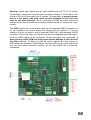
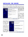
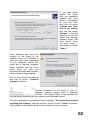
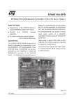
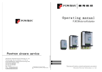
AxeMotion
PROFILER KIT
USER'S GUIDE
SAFETY INSTRUCTIONS
Please keep this user's guide! It contains important instructions you should
refer to when installing, maintaining and using your AxeMotion module and the
machine it drives. It has been written for people who use, configure, install,
handle or maintain this hardware.
Electric hazard:
To avoid risks of fire and injuries due to electric shocks, pay attention to the
safety guidelines when using this product.
- Carefully read and study the instructions of this user's guide.
- Always use a grounded outlet for the electric connection of the machine. If
you do not know if your socket outlet provides a ground plug, then get info rmation from a qualified electrician.
- Unplug all electrical connections before cleaning the hardware.
- Do not install the AxeMotion module or the machine it drives near water or in
an moist environment. Do not handle or use the machine if you are wet.
- Always install your hardware on a stable flat bed, in a clean and protected
place where nobody can step or stumble on electric connection cables.
Safety instructions for use:
Warning: to avoid any risk of injury due to eventual projections
when using an automated machine tool, including in manual
mode, you must imperatively wear safety eyeglasses.
Furthermore, depending on the type and the
use of your machine, it must be integrated in an approved
safety cabinet or protected area.
--2--
WARRANTY / LIABILITY
The AxeMotion CNC modules are guaranteed against defects in materials and
workmanship for one full year from the date of pu rchase.
This warranty cannot apply if electrical connections and prescriptions of use
that are described in this guide have been strictly observed. An installation that
does not comply with these prescriptions invalidates the warranty for cons equent damages.
AxeMotion CNC modules are provided without any warranty, even implicit,
concerning the results that can be obtained by their use, or the fact that any
user will be able to run them successfully, or regarding overall satisfaction with
the end products which can be obtained using the modules. The purchaser
explicitly recognises that he/she is solely responsible for choosing this module,
for running and using it and its related sof tware, and for obtaining the actual
results.
Connecting an AxeMotion CNC module requires skills in electrical wiring and
connecting, in motors and power stages, and in computerised motion control.
After integrating a CNC module, it is strongly recommended that the p urchaser
begins to get familiar with the machine control by making the first tests on
valueless workpieces.
Strict safety rules exist for building or using an automated machine tool. These
rules must be observed very accurately, and especially for the ele ctrical wiring,
the containment of mobile parts in a protection cabinet, the risks of injury
caused by impacts of chips or fragments of broken tools.
No liability can be accepted concerning the AxeMotion modules, their manufa cturer or distributor, for direct or indirect damages caused by a misuse or non
complying use, on persons who handle the module or the machine it drives, on
objects or materials subject to machine work, or on computer data subject to
the software processes.
Obviously none of the above terms and conditions may affect your statutory
rights under current law or legislation.
--3--
CH AR A CTE RI STI C S
Miscellaneous:
The AxeMotion kit for the Profiler is a plug-in card that must simply replace the
original control card of the machine. The power stage of the Profiler is the
mother-board and remains unchanged. The AxeMotion kit produces electrical signals that are compatible with this power stage but with a very high level
of performances.
The kit integrates an AxeMotion PulseMaker standard controller which is
plugged on a stage that interfaces with the power mother -board. The AxeMotion PulseMaker controller is a complete and high level numerical control
system, with very advanced functions. With its native USB link, its internal
memory buffer and its various interpolation commands, it is able to produce
very fast and smooth motion, especially in non-circular curves. Furthermore,
th
the AxeMotion PulseMaker card is able to manage peripheral devices (4 axis,
tool sensor, 3D digitising probe, spindle controller, etc.).
Important: the AxeMotion PulseMaker car is not opto-isolated, and exchanged
signals have TTL 0-5 V levels. A maximum of 20 mA is allowed on each input
and 10 mA on each output, with a total of 50 mA on the whole set of outputs.
Technical data:
- Connection and power supply on USB port (consumption < 90 mA)
- Control for 4 axes, interpolated simultaneously
- 35 KHz maximum frequency when interpolating
- 3.3 Ko local memory buffer (250 commands ahead)
- Interpolations at constant speed, variable speed, and double ramps
- Management of rapid decelerations along several chained vectors
- Speed override function for real-time speed control
- 12 inputs, 6 outputs plus 8 motor signals Clock / Dir
- Replaceable TTL drivers for outputs signals (mounted on sockets)
- 10 bit analog input (input # 1 with binary or analog access)
- integrated relay 10 A / 250 V (output # 5) with screw plug
- PWM output (output # 1) for spindle or hot wire control
- Optional 0-10 V / 10 mA analog output requiring no power supply
--4--
M OUNT I NG
The Profiler machine having itself been provided as a kit, unplugging its genuine control card and replacing it by the AxeMotion module should not cause any
problems.
Please first remove the box that contains the whole electronic set. It is located
inside the machine. Unplug the cables that lead to the motors and axis end
switches, and the RS-232 communication cable. Then open the box by unscrewing the cover so you get access to the internal electronic cards.
Now identify and remove the genuine control card. The DB-9 connector for the
RS-232 link should be also removed from the external side of the box. This
card is not screwed to the mother-board but is simply fixed by its electrical
connections, so you just have to lift it up gently but firmly.
The AxeMotion kit is mechanically and electrically compatible with the
mother-board. At the location which is now free, put the kit and plug the
connectors on their corresponding opposites without bending or damaging
them, exactly as you could have replugged your original card. Make sure that
the kit is firmly engaged with no bad connections, and then plug a USB cable
(type A-B) on the corresponding connector of the PulseMaker card. This USB
cable can go outside the box through one of the available connector holes on
the lateral side.
If you have extra peripherals you wish to integrate to the additional set of
inputs/outputs (relay or spindle control, tool sensor or 3D digitising probe on the
th
"Sensor" connector of the interface card, rotary 4 axis, etc.), then it is time to
connect them.
Now close the metal box and put it back to its location in the machine. Do not
forget to replug the motor and switch cables. The kit is ready.
Please note that a USB communication may be bad if the cable runs too close
to a source of radioelectrical noise (motors, power supplies, neon tubes, etc.).
Do not leave the USB cable run in the neighbourhood of a possible
source of noise.
--5--
SIDE CONNECTIONS
Important: before making any changes in the card wiring, always put it offpower (unplug the USB cable and cut the current of the power stage and all
peripheral devices). A bad quality wiring is the cause of continuous erro rs and
problems. Please be very careful with electrical connections.
In addition to the standard control of the Profiler, the AxeMotion kit provides
extra inputs/outputs to let you manage periphera ls. Three pairs of Clock/Dir
motor signals out of four are used for driving the machine power stage. The
fourth pair is therefore available for a 4 th axis, but it is up to you to mount the
motor and mechanical components, the power stage and its power supply.
Eight inputs are directly available from the PulseMaker card. These inputs are
default pulled up to the card +5 V. Consequently, an input is triggered when it is
connected to the card ground (GND). Either normally
open (NO) or normally closed (NC), a sensor must then
establish a contact between the chosen input and the
ground, no other modes being valid. Inputs are available
from two connectors, the first one giving access to inputs #1 to #4. Inputs #5 to
#7 are reserved for the machine end-switches (resetting the machine zero), and
the input #8 is available in 0-15 V mode on the interface card for the tool sensor
(using a higher voltage than 5 V reduces the possible noise). The second
connector gives access to the inputs #9 to #12. Each connector also provides a
GND pin. Please note that the input #1 may be read as a 0-5 V binary input
(instable state between 0.8 v and 2.4 V) or as a 10 bit analog input. If you have
a 0-5 V analog probe, its + pole should be connected to this input #1.
Three outputs are available, numbered from 1 to 3. They provide a default low
state (0 V), and a high state (+5 V) when activated. These outputs can drive
peripheral devices, each connector providing an additional GND pin. Please
note that the output #1 may be used either as a binary output or as a PWM
output for an external control.
A power relay can be triggered through the output #5. If you do not wish to
drive your spindle from that relay, then it is better to use an intermediate voltage. Do not let the mains voltage get through the card; its tracks and its
isolation have not been made for that. In addition to a real danger of electrocution, please keep in mind that a shortcut or an electrical failure may cause
severe damage to the machine and destroy any connected electrical equipment, including the host computer and its peripherals.
--6--
Warning: inputs and outputs are not opto-isolated and use TTL 0-5 V levels.
Furthermore, outputs can only provide a maximum current of 10 mA each, with
a total of 50 mA for the whole set of outputs. Consequently, a wrong connection or a too heavy load may cause serious damages on the card and
even on the host computer. So is it important to make sure that all devices
that are driven from the card and correctly isolated and do not require too much
current.
The USB connection can be made either on the classical USB -B connector or
on the neighbour pins (then please be careful with the signal s). If, for any
reasons, you do not wish to plug a classical USB A-B to the standard USB-B
connector of the card, then you can still use the four neighbour pins that repr oduce the USB signals of the connector. Check accurately the connection: a
wrong wiring on the USB port may cause serious damage to the card and
the host computer. To help you find the correct signals, the wire colours in
USB cables are standard. Unfortunately, the connection plug on the board with
only four pins cannot provide a locator. So, be very careful not to invert the
connection.
--7--
INSTALLING THE DRIVER
When the AxeMotion PulseMaker module is plugged for the first time on the
USB port of a PC under Windows, the system needs to install a driver to allow
dialoguing with this new peripheral. A message "New Hardware detected" is
followed by a "Welcome to the Found
New Hardware Wizard", allowing you to
tell Windows how this
driver should be installed.
To the first prompt
"Can Windows connect to Windows
Update to search for
software?",
answer
"No, not this time"
and then click on
button "Next >" at the
bottom of the dialog
box.
The next dialog box
remains you that you
are about to install
the software driver
for the "USB AxeMotion PulseMaker".
If you have got a CD
provided with the
card, please insert it
in the drive: Windows will then seek
for the driver on that
CD. Otherwise click
on "Install from a
list
or
specific
location" then down
on button "Next >".
--8--
If you have downloaded the driver
from the AxeMotion
website and have
saved it somewhere
on your hard disk,
then click on option
"Include this location in the search"
and use the button
"Browse" to find the
directory on the disk
where the uncompresssed driver has
been stored. Once
you have found it,
click down on button
"Next >".
Once Windows has found the
location of the driver to be
installed, from the CD-ROM or
from your hard disk, depending
on your Windows version you
might get a warning message
which indicates that the driver
found does not have any
Windows certificate and therefore
recommends to stop installing.
Do not worry about this warning
and skip to button "Continue
Anyway" at bottom.
Normal installation of the driver is then in
progress, copying system files to Windows
directory. This usually takes a few seconds but
may be longer depending on the computer and Windows version.
Once the installation is completed, a last message "The wizard has finished
installing the software" ends the process. Click on button "Finish" at bottom.
The AxeMotion PulseMaker driver is now installed on your computer.
--9--
UNINSTALLING THE DRIVER
In case you encounter system
configuration problems or experience communication failure
with the AxeMotion module, you
might want to uninstall your
PulseMaker driver from your
computer. In Windows "Start"
menu, click on "Parameters"
then on "Control Panel" (also
available from the Windows File
Explorer).
Double-click on the "System"
icon or line. In the multiple page
dialog box this pops up, open
the "Hardware" section tab and
then click on button "Device
Manager".
The list of devices that are already installed on your computer is displayed in a
new window. Double-click on line
"Universal Serial Bus controllers" to see the USB peripherals
that are connected. The module
"USB AxeMotion PulseMaker"
should appear in that sublist, if it is
still alive seen from the computer.
Click on its line using the right
mouse button and, in the context
menu that pops up, click on option
"Uninstall" and confirm that you
want to remove the device. Your
AxeMotion driver is then suppressed from your computer. If you
wish to re-install it, just plug the
module again and return to the
normal installation procedure.
--10--
PARAMETERS IN GALAAD
The AxeMotion kit for Profiler is provided with the integrated CAD-CAM-CNC
software Galaad which is able to drive the whole set with optimal performance.
In Galaad or one of its
related modules, call the
menu command "Parameters / Machine / Full
data". The first page
"Table" allows you to
select
directly
the
"Colinbu Profiler" with
the AxeMotion kit. The
whole set of parameters
is then automatically
configured
for
your
machine and you do not
have to worry about any
mechanical or electrical
settings.
Click then at top on the
tab that correspond to
the page "Controller"
and indicate here that
the communication runs
on a USB port. Validate
the dialog box by clicking
on "OK". That is all.
Galaad is configured to
drive your new profiler.
Now you just have to
switch it on and try a
manual drive to begin.
--11--
Galaad uses absolute co-ordinates only. At the very first initialisation, or anytime the card has been powered off (USB cable unplugged or computer shutdown), it is going to make a reference run to reset the machine zero point.
Depending on how you have connected the motors , it may occur that the axes
go toward the right direction or the wrong direction. The Z axis must imperatively lift up, the Y axis toward the front of the machine, and the X axis toward
the left of the machine (seen from the front). If one of the motions goes toward
the wrong direction, then switch off the machine immediately and shut the
driving window.
Then return to the
machine full data, "Advanced" tab page, and
enable or disable the
corresponding axis inversion, validate the
window and try a new
manual
drive
after
having unplugged and
replugged the USB port
so the card is reinitialised. Once all axes go
toward
the
correct
direction when seeking
for the machine zero, the
configuration is over.
If, for any reasons, you have lost some configuration parameters, just re-select
the "Colinbus / Profiler - AxeMotion" machine in the parameters. This reinitialises the whole set of parameters to the default values for the machine. Please
check accurately that the communication port is still "USB" and restore the axis
inversions to the states that correspond to your machine.
--12--
You may install Galaad software on as many computers as needed, for
example to have a design workstation and a milling workstation. In that case,
the milling workstation must be the one that gets Galaad licence key.
If you have connected peripherals to your AxeMotion PulseMaker card and
wish to test them, please use in Galaad the command "Parameters / Machine /
I-O test". This helps you find which sensor is connected to which input with
which polarity. A normally dark input that lights up when the switch is triggered
corresponds to an "Enabled (NO)" input. Reciprocally, if the input is normally
light and darkens when the switch is triggered, then the polarity is "Disabled
(NC)". You may also click on green zones that correspond to outputs to enable
or disable them. Warning: some outputs are reserved for internal machine
functions, for example activating the motor power stage.
Please refer to Galaad user's manual for more advanced information about this
software and its functions.
--13--
T R OU B L E S H OOT I NG
- The computer does not detect the card
Please check the USB connection and the correct installation of the driver that
corresponds to the card (see previous pages). The system must react when the
card is plugged or unplugged, and must display "AxeMotion PulseMaker" in the
list of available USB peripherals. In Galaad, call "Parameters / Machine / Full
data", page "Controller" and click on button "Device manager". List the set of
USB controllers: the line "USB AxeMotion PulseMaker" should appear. If not,
check your USB cable and its connection to th e AxeMotion card. If you have a
USB hub or extension cable, first try without. Then try to plug the cable on
another USB port. On the other hand, if the line "USB AxeMotion PulseMaker"
appears but with an icon that indicates a problem, then it is better to uninstall
the driver. Just click on the line with the right mouse button and call "Uninstall"
(see "Uninstalling the driver" section in previous pages). Unplug and replug the
card, which will trigger a new installation for the driver.
- A motor does not turn, or no motors are turning
The AxeMotion kit is probably badly connected to the mother-board. Remove
and reopen the electric cabinet, then check that all connectors are straight,
clean and in good conditions. Eventually proceed with a careful cleaning of the
connectors using a spray or any compatible solvent. Check that the two cards
of the kit are well connected with no bad contacts. Also check that the whole kit
is firmly in place on the mother-board. Do not try to make motors turn faster
than they can: stepper motors will block at start up instead of turning, but since
there are no feedback loops, neither the card or the software will know about it.
- A motor turns in the wrong direction
If the motion is fast, then the axis is inverted and its direction must be changed
in the software parameters (see function "Parameters / Machine / Full data",
page "Advanced"). On the other hand, if the motion is slow, then probably the
end-switch input is wrongly set, i.e. the indicated input does not actually correspond to the switch or the polarity NO/NC is reversed. The software thinks the
axis is blocked in the switch and tries to release it.
--14--
- An axis does not stop during the reference run
The input that actually corresponds to the zero-end switch is not the one that
has been parametered, or the switch is not working, or is not triggered by the
axis, or the connection wire is cut or unplugged.
- An axis drifts during the milling process
A motor may lose steps when the feed strength is too important, the rotation
speed too high, or a speed change too abrupt. Make your first tests at little
depths on a tender material to check the first point. Then reduce the milling
speed and the inactive motion speeds to see if the motors do not turn too fast.
At last, reduce the parameters of the kinematical post-calculation. This calculation avoids too high speed jumps. Default parameters have be en fully tested on
the Profiler, but stepper motors may lose torque when getting old and it can
happen that your machine requires smoother values. Galaad provides a semimanual calibration function that helps setup these parameters.
--15--
www.axemotion.com
AxeMotion
/
106 rue de la placette
RCS Grasse 411 582 471
/
/
06620 Cipieres
SIRET 411 582 471 00024
Copyright © 2008 AxeMotion
/
All rights reserved
/
France