1
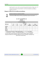
BreezeMAX Si 3000 and BreezeMAX PRO 3000 Product Manual Software Version: 4.6 October 2009 P/N 215307 Document History Document History Changed Item Description Date This is the document’s first publication. BreezeMAX Si 3000 and BreezeMAX PRO 3000 October 2009 ii Product Manual Legal Rights Legal Rights © Copyright 2009 Alvarion Ltd. All rights reserved. The material contained herein is proprietary, privileged, and confidential and owned by Alvarion or its third party licensors. No disclosure thereof shall be made to third parties without the express written permission of Alvarion Ltd. Alvarion Ltd. reserves the right to alter the equipment specifications and descriptions in this publication without prior notice. No part of this publication shall be deemed to be part of any contract or warranty unless specifically incorporated by reference into such contract or warranty. Trade Names Alvarion®, BreezeCOM®, WALKair®, WALKnet®, BreezeNET®, BreezeACCESS®, BreezeLINK®, BreezeMAX®, BreezeLITE®, BreezePHONE®, 4MOTION®, BreezeCONFIG™, MGW™, eMGW™ and/or other products and/or services referenced here in are either registered trademarks, trademarks or service marks of Alvarion Ltd. All other names are or may be the trademarks of their respective owners. “WiMAX Forum” is a registered trademark of the WiMAX Forum. “WiMAX,” the WiMAX Forum logo, “WiMAX Forum Certified,”andtheWiMAX Forum Certified logo are trademarks of the WiMAX Forum. Statement of Conditions The information contained in this manual is subject to change without notice. Alvarion Ltd. shall not be liable for errors contained herein or for incidental or consequential damages in connection with the furnishing, performance, or use of this manual or equipment supplied with it. Warranties and Disclaimers All Alvarion Ltd. (“Alvarion”) products purchased from Alvarion or through any of Alvarion's authorized resellers are subject to the following warranty and product liability terms and conditions. Exclusive Warranty (a) Alvarion warrants that the Product hardware it supplies and the tangible media on which any software is installed, under normal use and conditions, will be free from significant defects in materials and workmanship for a period of fourteen (14) months from the date of shipment of a given Product to Purchaser (the “Warranty Period”). Alvarion will, at its sole option and as Purchaser's sole BreezeMAX Si 3000 and BreezeMAX PRO 3000 iii Product Manual Legal Rights remedy, repair or replace any defective Product in accordance with Alvarion' standard R&R procedure. (b) With respect to the Firmware, Alvarion warrants the correct functionality according to the attached documentation, for a period of fourteen (14) month from invoice date (the “Warranty Period”). During the Warranty Period, Alvarion may release to its Customers firmware updates, which include additional performance improvements and/or bug fixes, upon availability (the “Warranty”). Bug fixes, temporary patches and/or workarounds may be supplied as Firmware updates. Additional hardware, if required, to install or use Firmware updates must be purchased by the Customer. Alvarion will be obligated to support solely the two (2) most recent Software major releases. ALVARION SHALL NOT BE LIABLE UNDER THIS WARRANTY IF ITS TESTING AND EXAMINATION DISCLOSE THAT THE ALLEGED DEFECT IN THE PRODUCT DOES NOT EXIST OR WAS CAUSED BY PURCHASER'S OR ANY THIRD PERSON'S MISUSE, NEGLIGENCE, IMPROPER INSTALLATION OR IMPROPER TESTING, UNAUTHORIZED ATTEMPTS TO REPAIR, OR ANY OTHER CAUSE BEYOND THE RANGE OF THE INTENDED USE, OR BY ACCIDENT, FIRE, LIGHTNING OR OTHER HAZARD. Disclaimer (a) THE SOFTWARE IS SOLD ON AN “AS IS” BASIS. ALVARION, ITS AFFILIATES OR ITS LICENSORS MAKE NO WARRANTIES, WHATSOEVER, WHETHER EXPRESS OR IMPLIED, WITH RESPECT TO THE SOFTWARE AND THE ACCOMPANYING DOCUMENTATION. ALVARION SPECIFICALLY DISCLAIMS ALL IMPLIED WARRANTIES OF MERCHANTABILITY AND FITNESS FOR A PARTICULAR PURPOSE AND NON-INFRINGEMENT WITH RESPECT TO THE SOFTWARE. UNITS OF PRODUCT (INCLUDING ALL THE SOFTWARE) DELIVERED TO PURCHASER HEREUNDER ARE NOT FAULT-TOLERANT AND ARE NOT DESIGNED, MANUFACTURED OR INTENDED FOR USE OR RESALE IN APPLICATIONS WHERE THE FAILURE, MALFUNCTION OR INACCURACY OF PRODUCTS CARRIES A RISK OF DEATH OR BODILY INJURY OR SEVERE PHYSICAL OR ENVIRONMENTAL DAMAGE (“HIGH RISK ACTIVITIES”). HIGH RISK ACTIVITIES MAY INCLUDE, BUT ARE NOT LIMITED TO, USE AS PART OF ON-LINE CONTROL SYSTEMS IN HAZARDOUS ENVIRONMENTS REQUIRING FAIL-SAFE PERFORMANCE, SUCH AS IN THE OPERATION OF NUCLEAR FACILITIES, AIRCRAFT NAVIGATION OR COMMUNICATION SYSTEMS, AIR TRAFFIC CONTROL, LIFE SUPPORT MACHINES, WEAPONS SYSTEMS OR OTHER APPLICATIONS REPRESENTING A SIMILAR DEGREE OF POTENTIAL HAZARD. ALVARION SPECIFICALLY DISCLAIMS ANY EXPRESS OR IMPLIED WARRANTY OF FITNESS FOR HIGH RISK ACTIVITIES. BreezeMAX Si 3000 and BreezeMAX PRO 3000 iv Product Manual Legal Rights (b) PURCHASER'S SOLE REMEDY FOR BREACH OF THE EXPRESS WARRANTIES ABOVE SHALL BE REPLACEMENT OR REFUND OF THE PURCHASE PRICE AS SPECIFIED ABOVE, AT ALVARION'S OPTION. TO THE FULLEST EXTENT ALLOWED BY LAW, THE WARRANTIES AND REMEDIES SET FORTH IN THIS AGREEMENT ARE EXCLUSIVE AND IN LIEU OF ALL OTHER WARRANTIES OR CONDITIONS, EXPRESS OR IMPLIED, EITHER IN FACT OR BY OPERATION OF LAW, STATUTORY OR OTHERWISE, INCLUDING BUT NOT LIMITED TO WARRANTIES, TERMS OR CONDITIONS OF MERCHANTABILITY, FITNESS FOR A PARTICULAR PURPOSE, SATISFACTORY QUALITY, CORRESPONDENCE WITH DESCRIPTION, NON-INFRINGEMENT, AND ACCURACY OF INFORMATION GENERATED. ALL OF WHICH ARE EXPRESSLY DISCLAIMED. ALVARION' WARRANTIES HEREIN RUN ONLY TO PURCHASER, AND ARE NOT EXTENDED TO ANY THIRD PARTIES. ALVARION NEITHER ASSUMES NOR AUTHORIZES ANY OTHER PERSON TO ASSUME FOR IT ANY OTHER LIABILITY IN CONNECTION WITH THE SALE, INSTALLATION, MAINTENANCE OR USE OF ITS PRODUCTS. Limitation of Liability (a) ALVARION SHALL NOT BE LIABLE TO THE PURCHASER OR TO ANY THIRD PARTY, FOR ANY LOSS OF PROFITS, LOSS OF USE, INTERRUPTION OF BUSINESS OR FOR ANY INDIRECT, SPECIAL, INCIDENTAL, PUNITIVE OR CONSEQUENTIAL DAMAGES OF ANY KIND, WHETHER ARISING UNDER BREACH OF CONTRACT, TORT (INCLUDING NEGLIGENCE), STRICT LIABILITY OR OTHERWISE AND WHETHER BASED ON THIS AGREEMENT OR OTHERWISE, EVEN IF ADVISED OF THE POSSIBILITY OF SUCH DAMAGES. (b) TO THE EXTENT PERMITTED BY APPLICABLE LAW, IN NO EVENT SHALL THE LIABILITY FOR DAMAGES HEREUNDER OF ALVARION OR ITS EMPLOYEES OR AGENTS EXCEED THE PURCHASE PRICE PAID FOR THE PRODUCT BY PURCHASER, NOR SHALL THE AGGREGATE LIABILITY FOR DAMAGES TO ALL PARTIES REGARDING ANY PRODUCT EXCEED THE PURCHASE PRICE PAID FOR THAT PRODUCT BY THAT PARTY (EXCEPT IN THE CASE OF A BREACH OF A PARTY'S CONFIDENTIALITY OBLIGATIONS). Radio Frequency Interference Statement The Subscriber Unit equipment has been tested and found to comply with the limits for a class B digital device, pursuant to ETSI EN 301 489-1 rules and Part 15 of the FCC Rules. These limits are designed to provide reasonable protection against harmful interference when the equipment is operated in a residential environment notwithstanding use in commercial, business and industrial environments. This equipment generates, uses, and can radiate radio frequency energy and, if not installed and used in accordance with the instruction manual, may cause harmful interference to radio communications. BreezeMAX Si 3000 and BreezeMAX PRO 3000 v Product Manual Legal Rights FCC Radiation Hazard Warning Indoor CPE - To comply with FCC RF exposure requirements in Section 1.1307and 2.1091 of FCC Rules, the antenna used for this transmitter must be kept at a separation distance of at least 20 cm from all persons and must not be co-located or operating in conjunction with any other antenna or transmitter. Outdoor CPE - To comply with FCC RF exposure requirements in Section 1.1307 and 2.1091 of FCC Rules, the antenna be used for this transmitter must be fixed-mounted on outdoor permanent structures with a separation distance of at least 120 cm from all persons and must not be co-located or operating in conjunction with any other antenna or transmitter. R&TTE Compliance Statement This equipment complies with the appropriate essential requirements of Article 3 of the R&TTE Directive 1999/5/EC. Safety Considerations - General For the following safety considerations, “Instrument” means the BreezeMAX units' components and their cables. Caution To avoid electrical shock, do not perform any servicing unless you are qualified to do so. Line Voltage Before connecting this instrument to the power line, make sure that the voltage of the power source matches the requirements of the instrument. Radio The instrument transmits radio energy during normal operation. To avoid possible harmful exposure to this energy, do not stand or work for extended periods of time in front of its antenna. The long-term characteristics or the possible physiological effects of radio frequency electromagnetic fields have not been yet fully investigated. Outdoor Units and Antennas Installation and Grounding Ensure that outdoor units, antennas and supporting structures are properly installed to eliminate any physical hazard to either people or property. Make sure that the installation of the outdoor unit, antenna and cables is performed in accordance with all relevant national and local building and safety codes. Even where grounding is not mandatory according to applicable regulation and national codes, it is highly recommended to ensure that the outdoor unit and the antenna mast (when using external antenna) are grounded and suitable lightning BreezeMAX Si 3000 and BreezeMAX PRO 3000 vi Product Manual Legal Rights protection devices are used so as to provide protection against voltage surges and static charges. In any event, Alvarion is not liable for any injury, damage or regulation violations associated with or caused by installation, grounding or lightning protection. Disposal of Electronic and Electrical Waste Disposal of Electronic and Electrical Waste Pursuant to the WEEE EU Directive electronic and electrical waste must not be disposed of with unsorted waste. Please contact your local recycling authority for disposal of this product. BreezeMAX Si 3000 and BreezeMAX PRO 3000 vii Product Manual Important Notice Important Notice This user manual is delivered subject to the following conditions and restrictions: This manual contains proprietary information belonging to Alvarion Ltd. Such information is supplied solely for the purpose of assisting properly authorized users of the respective Alvarion products. No part of its contents may be used for any other purpose, disclosed to any person or firm or reproduced by any means, electronic and mechanical, without the express prior written permission of Alvarion Ltd. The text and graphics are for the purpose of illustration and reference only. The specifications on which they are based are subject to change without notice. The software described in this document is furnished under a license. The software may be used or copied only in accordance with the terms of that license. Information in this document is subject to change without notice. Corporate and individual names and data used in examples herein are fictitious unless otherwise noted. Alvarion Ltd. reserves the right to alter the equipment specifications and descriptions in this publication without prior notice. No part of this publication shall be deemed to be part of any contract or warranty unless specifically incorporated by reference into such contract or warranty. The information contained herein is merely descriptive in nature, and does not constitute an offer for the sale of the product described herein. Any changes or modifications of equipment, including opening of the equipment not expressly approved by Alvarion Ltd. will void equipment warranty and any repair thereafter shall be charged for. It could also void the user's authority to operate the equipment. BreezeMAX Si 3000 and BreezeMAX PRO 3000 viii Product Manual Contents Contents 1. Overview .............................................................................................. 1 1.1 BreezeMAX Si 3000 ......................................................................................................1 1.1.1 Top Panel LEDs ..................................................................................................1 1.1.2 Rear Panel ..........................................................................................................2 1.2 BreezeMAX PRO 3000..................................................................................................2 1.3 Specifications ...............................................................................................................3 1.3.1 BreezeMAX PRO 3000 CPE Specifications........................................................3 1.3.2 Si 3000 CPE Specifications ................................................................................6 2. Installation........................................................................................... 9 2.1 BreezeMAX PRO 3000..................................................................................................9 2.1.1 Package Content.................................................................................................9 2.1.2 Additional Installation Requirements...................................................................9 2.1.3 Guidelines for Positioning the ODU ....................................................................9 2.1.4 IDU-ODU Cables...............................................................................................10 2.1.5 Pole Mounting the ODU ....................................................................................11 2.1.6 Connecting the Cables......................................................................................16 2.1.7 Installing the Power Injector IDU.......................................................................18 2.2 BreezeMAX Si 3000 ....................................................................................................19 2.2.1 Package Content...............................................................................................19 2.2.2 Additional Installation Requirements.................................................................19 2.2.3 Guidelines for Positioning the CPE ...................................................................19 2.2.4 Connecting the Si CPE .....................................................................................19 BreezeMAX Si 3000 and BreezeMAX PRO 3000 ix Product Manual Contents 3. Configuring the CPEs Using the Configuration Application ............. 21 3.1 Logging In ...................................................................................................................21 3.2 The Main Window .......................................................................................................22 3.3 Rebooting....................................................................................................................23 3.4 Configuring Status Settings......................................................................................24 3.4.1 WiMAX Status ...................................................................................................24 3.4.2 Network Status..................................................................................................24 3.4.3 Device Status ....................................................................................................25 3.5 Personalization of CPE Settings...............................................................................26 3.5.1 Account .............................................................................................................26 3.5.2 Date...................................................................................................................26 3.5.3 Language ..........................................................................................................27 3.6 Configuring WiMAX Settings ....................................................................................28 3.6.1 NDS...................................................................................................................28 3.6.2 Scanner.............................................................................................................29 3.6.3 Authentication ...................................................................................................31 3.7 Configuring Networking Parameters.......................................................................32 3.7.1 Bridge/NAT Mode..............................................................................................32 3.7.2 Firewall..............................................................................................................34 3.7.3 DHCP Server ....................................................................................................35 3.7.4 NAT ALG...........................................................................................................37 3.7.5 Port Forwarding.................................................................................................37 3.7.6 Port Trigger .......................................................................................................39 3.7.7 DDNS ................................................................................................................40 3.8 Configuring Management Settings...........................................................................41 3.8.1 TR-069 ..............................................................................................................41 BreezeMAX Si 3000 and BreezeMAX PRO 3000 x Product Manual Contents 3.8.2 Buzzer ...............................................................................................................43 3.8.3 Log ....................................................................................................................44 3.8.4 Upgrade ............................................................................................................45 3.8.5 Recovery ...........................................................................................................46 4. Creating a Default Configuration File ............................................... 48 5. Creating a CDROM for the Subscriber .............................................. 51 6. Glossary ............................................................................................. 52 BreezeMAX Si 3000 and BreezeMAX PRO 3000 xi Product Manual Overview 1. BreezeMAX Si 3000 Overview The IEEE 802.16e Wave II standard WiMAX-compatible BreezeMAX PRO 3000 CPE and BreezeMAX Si 3000 CPE Subscriber Units (SUs) serve as an efficient platform for a wide range of services, providing basic WiMAX connectivity and bridge functionality. The BreezeMAX Si 3000 (indoor unit) is available at 2496-2690MHz. The BreezeMAX PRO 3000 (outdoor unit) is available at 3.3-3.6 GHz and 2.496-2.69GHz bands. 1.1 BreezeMAX Si 3000 The Self Install Si CPE is a compact Subscriber Unit (SU) that is intended for indoor installations. Figure 1: BreezeMAX Si CPE 1.1.1 Top Panel LEDs Table 1: Front Panel LED Indicators Name Functionality Power On - Power on Off - Power off LAN On - Connected Off - Disconnected Blinking - Data transmission BreezeMAX Si 3000 and BreezeMAX PRO 3000 1 Product Manual Overview BreezeMAX PRO 3000 Table 1: Front Panel LED Indicators (Continued) Name Functionality Red ONLY Blinking - Synchronization On - Weak signal (CINR<8dB) Off Blinking - Authentication Yellow ONLY On - Medium signal strength (8dB<CINR<15dB) Off Blinking - Synchronization with base station Green ONLY On - Good signal strength (15dB<CINR) Off Figure 2: BreezeMAX Si 3000 Front Panel 1.1.2 Rear Panel Power jack: DC 12V / 1.5A LAN port: 10/100Base-TX Reset button: To reboot the CPE 1.2 BreezeMAX PRO 3000 The PRO 3000 CPE comprises an Outdoor Unit (ODU) and an Indoor Unit (IDU). The ODU includes the modem, radio, data processing and management components of the SU. It also includes an integral high-gain flat antenna. The ODU connects to the IDU and to the user's equipment through a 10/100BaseT Ethernet port. The indoor unit is powered from the mains and connects to the ODU via a Category 5E Ethernet cable carrying the Ethernet data between the two units, as BreezeMAX Si 3000 and BreezeMAX PRO 3000 2 Product Manual Overview Specifications well as power (-54 VDC) and control signals to the ODU and status indications from the ODU. Figure 3: BreezeMAX PRO 3000 1.3 Specifications 1.3.1 BreezeMAX PRO 3000 CPE Specifications 1.3.1.1 Radio Specifications Table 2: PRO 3000 CPE Radio Specifications Item Details General Frequency Band Frequencies (GHz) Channel Bandwidth 2.5 GHz 2.496-2.690 5 / 10 MHz 3.5 GHz 3.3-3.6 3.5 (Optional)/ 5/ 7/10 MHz Channel Step Size In 125kHz steps Synchronization Shall be referenced to the WiMax BTS Timing Module. Frequency Accuracy MRCT Compliant Air Interface IEEE 802.16e WirelessMAN-OFDMA Standards compliance IEEE 802.16e and Standard for Conformance to IEEE Standard (Radio Compliance Test) Wave1/ Wave2 TDD Duty Cycle (Tx/Rx) Rx up to 75% , Tx up to 50% SISO or MIMO MIMO (1Tx, 2Rx ) Regulatory Compliance Comply with major regional regulatory requirements Frame duration 5 msec; BreezeMAX Si 3000 and BreezeMAX PRO 3000 3 Product Manual Overview Specifications Table 2: PRO 3000 CPE Radio Specifications (Continued) Item Details RF Transmitter Specifications Maximum output power 2.496 - 2.69 / 2.3 - 2.4 GHz Typical 27dBm @ (16QAM) 3.3 - 3.6 GHz Typical 27dBm @ (16QAM) w/ ETSI Mask RF dynamic range 45dB minimum Transmit Power Control Relative Accuracy mRCT compliant Transmit and Receive Switching Gap 50uS RF Receiver Specifications Impedance 50 ohms nominal Input return loss 10dBi RX Sensitivity Typical 3dB better than mRCT in SISO mode, and 6 dB better in MRC or MIMO mode. Adjacent Channel Rejection Meet mRCT requirement ( Typical 3dB better) Non-Adjacent Channel Rejection Meet mRCT requirement ( Typical 3dB better) Antenna Specifications Antenna Polarization Type Directional Dual Polarization Patch Ant Antenna Gain Typical 15 dBi Antenna Connectors No External ANT Connector / and 2 internal MCX ANT connector IMPORTANT The related parameters are all defined at the room temperature condition of 25°C ~ 35°C 1.3.1.2 Power Specification Table 3: PRO 3100 CPE Power Specification Item Details Power Consumptions Outdoor CPE: 12.9W Maximum Power Adapter Input of 100 VAC - 240 VAC 50 Hz to 60 Hz Power over Ethernet 48V DC BreezeMAX Si 3000 and BreezeMAX PRO 3000 4 Product Manual Overview 1.3.1.3 Specifications Environmental Specifications Table 4: PRO 3000 CPE Environmental Specifications Item Details Operating Temperature -40°C ~ 60°C Storage Temperature -40°C ~ 70°C Operating and Storage Humidity 5%-95% 1.3.1.4 Interface Table 5: PRO 3000 CPE Interface Specifications Item Details RJ 45 Ethernet connection: 1 RJ 45 Buzzer Signal Strength 1.3.1.5 Regulatory Specifications Table 6: PRO 3000 CPE Regulatory Specifications Standard Frequency Band EMC: 2.5~2.7 GHz EN 301 489-1/-4 3.4~3.6 GHz FCC p15 Radio: EN 302 326 EN 302 544-2 FCC p27 Safety: EN 60950-1 UL 60950-1 BreezeMAX Si 3000 and BreezeMAX PRO 3000 5 Product Manual Overview 1.3.1.6 Specifications Reliability Specifications Table 7: PRO 3000 CPE Reliability Specifications Item Details MTBF The MTBF for CPE is not less than 200,000 hours. 1.3.2 Si 3000 CPE Specifications 1.3.2.1 Radio Specifications Table 8: Si 3000 CPE Radio Specifications Item Details General Frequency Band Frequencies (GHz) Channel Bandwidth 2.5 GHz g 2.496-2.690 5 / 10 MHz Channel Step Size In 125kHz steps Synchronization Shall be referenced to the WiMax BTS Timing Module. Frequency Accuracy MRCT Compliant Air Interface IEEE 802.16e WirelessMAN-OFDMA Standards compliance IEEE 802.16e and Standard for Conformance to IEEE Standard (Radio Compliance Test) Wave1/ Wave2 TDD Duty Cycle (Tx/Rx) Rx up to 75% , Tx up to 50% SISO or MIMO MIMO (1TX, 2RX ) / 3.xGHz support 2Tx in future upgrade Regulatory Compliance Comply with major regional regulatory requirements Frame duration 5 msec; RF Transmitter Specifications Maximum output power 2.496 - 2.69 RF dynamic range 45dB minimum Transmit Power Control Relative Accuracy mRCT compliant Transmit and Receive Switching Gap 50uS Typical 27dBm @ (16QAM) RF Receiver Specifications Impedance 50 ohms nominal Input return loss 10dBi BreezeMAX Si 3000 and BreezeMAX PRO 3000 6 Product Manual Overview Specifications Table 8: Si 3000 CPE Radio Specifications (Continued) Item Details RX Sensitivity Typical 3dB better than mRCT in SISO mode, and 6 dB better in MRC or MIMO mode. Adjacent Channel Rejection Meet mRCT requirement ( Typical 3dB better) Non-Adjacent Channel Rejection Meet mRCT requirement ( Typical 3dB better) Antenna Specifications Antenna Polarization Type Embedded Dipole Antenna Gain Typical 5dBi Antenna Connectors None. Embedded IPEX IMPORTANT The related parameters are all defined at the room temperature condition of 25°C ~ 35°C 1.3.2.2 Power Specification Table 9: Si 3000 CPE Power Specification Item Details Power Consumption 12W Maximum Power Adapter Input of 100 VAC - 240 VAC 50 Hz to 60 Hz 1.3.2.3 Environmental Specifications Table 10: Si 3000 CPE Environmental Specifications Item Details Operating Temperature 0°C ~ 45°C Storage Temperature -5°C ~ 70°C Operating and Storage Humidity 5%-95% 1.3.2.4 Interface Table 11: Si 3000 CPE Interface Specifications Item Details RJ 45 Ethernet connection: 1 RJ 45 BreezeMAX Si 3000 and BreezeMAX PRO 3000 7 Product Manual Overview Specifications Table 11: Si 3000 CPE Interface Specifications (Continued) Item Details Reset Signal Button LEDs Signal Strength: 3 LEDs Power: 1 LED LAN: 1 LED 1.3.2.5 Regulatory Specifications Table 12: Si 3000 CPE Regulatory Specifications Standard Frequency Band EMC: 2.5~2.7GHz EN 301 489-1/-4 3.4~3.6GHz FCC p15 Radio: EN 302 326 EN 302 544-2 FCC p27 Safety: EN 60950-1 UL 60950-1 1.3.2.6 Reliability Specifications Table 13: Si 3000 CPE Reliability Specifications Item Details MTBF The MTBF for CPE is not less than 100,000 hours. BreezeMAX Si 3000 and BreezeMAX PRO 3000 8 Product Manual Installation BreezeMAX PRO 3000 2. Installation 2.1 BreezeMAX PRO 3000 2.1.1 Package Content BreezeMAX PRO 3000 ODU Power Injector - Power Over Ethernet 802.3af compliant with LAN port: 10/100Base-TX Crossed Ethernet cable with two RJ-45 connectors for connecting the IDU power injector to a PC/HUB/switch. Power Cable Sealing cap Pole mounting kit (see Table 15) 2.1.2 Additional Installation Requirements Indoor-to-outdoor Category 5E PoE Ethernet cable with two shielded RJ-45 connectors (can be ordered separately from Alvarion) and an RJ-45 connectors crimping tool. For details on approved cables and maximum length, refer to Section 2.1.4. Mains plug adapter or termination plug (if the power plug on the supplied AC power cord does not fit local power outlets). 2.1.3 Guidelines for Positioning the ODU This section provides key guidelines for selecting the optimal installation locations for the ODU. CAUTION ONLY experienced installation professionals who are familiar with local building and safety codes and, wherever applicable, are licensed by the appropriate government regulatory authorities should install outdoor units and antennas. Failure to do so may void the product warranty and may expose the end user or Service Provider to legal and financial liabilities. Alvarion and its resellers or distributors are not liable for injury, damage or regulation violations associated with the installation of Outdoor Units or antennas. BreezeMAX Si 3000 and BreezeMAX PRO 3000 9 Product Manual Installation BreezeMAX PRO 3000 Select the optimal locations for the equipment using the following guidelines: The ODU should be mounted on a 1"-4" pole. Its location should enable easy access to the unit and its connectors for installation and testing. The higher the placement of the antenna, the better the achievable link quality. The antenna should be installed to provide a direct, or near line of sight with the BTS antenna(s). The antenna should be aligned to face the general direction of the BTS. 2.1.4 IDU-ODU Cables NOTE The length of the Indoor-to-Outdoor cable should not exceed 90 meters. The length of the Indoor-to-Outdoor cable, together with the length of the Ethernet cable connecting the CPE-IDU-1D to the data equipment, should not exceed 100 meters. Use only Category 5E PoE Ethernet cables from either Alvarion or any of the approved manufacturers, listed in Table 14 below. Consult with Alvarion's specialists on the suitability of other cables. Table 14: Approved Category 5E Ethernet Cables Manufacturer Part Number Superior Cables Ltd. www.superior-cables.com 612098 HES Cabling Systems H5E-00481 www.hescs.com Teldor www.teldor.com 8393204101 Southbay Holdings Limited 11th Fl., 15, Lane 347, Jong Jeng Rd. Shin Juang City, Taipei County Taiwan, R.O.C. Attn: Eva Lin Tel. 886-2-2832 3339 Fax. 886-2-2206 0081 E-mail: [email protected] TSM2404A0D BreezeMAX Si 3000 and BreezeMAX PRO 3000 10 Product Manual Installation BreezeMAX PRO 3000 Table 14: Approved Category 5E Ethernet Cables (Continued) Manufacturer Part Number GU-Tech., LLC . - A Member of OVIS GroupTel/Fax : 732 918 8221 Mobile: 718 909 4093 www.OVIS.COM.TW www.GU-TECH.COM In case of missing information in the manufacturer's WEB site (product specifications, ordering issues, etc.), it is highly recommended to contact the manufacturer's sales representative directly. 2.1.5 Pole Mounting the ODU The ODU can be mounted on a 1" to 4" pole using the pole mounting kit supplied with each unit. The pole mounting kit includes the following items: Table 15: Pole Mounting Kit Item No. Item Item Description Qty 1 Bracket 1 2 Clamp 1 3 Clamp 1 4 Hex head M5*16mm bolts 2 5 M5 spring washers 2 6 Hex head M8*40mm bolts 2 BreezeMAX Si 3000 and BreezeMAX PRO 3000 11 Product Manual Installation BreezeMAX PRO 3000 Table 15: Pole Mounting Kit (Continued) Item No. Item Item Description Qty 7 M8 spring washers 5 8 M8 washer 1 9 Hex head M5*35mm bolt 1 10 M8 Hex nuts 3 11 Hex head M8*100mm bolt 2 In the following instructions the item numbers (within the text and in the drawings) refer to the pole mounting kit items listed in Table 15. 1 With the connector facing downward, attach the bracket (item 1) to the two designated holes at the rear of the ODU, as shown in Figure 4. Use the two M5*16mm bolts (item 4) and M5 spring washers (item 5). The assembled bracket is shown in Figure 5. BreezeMAX Si 3000 and BreezeMAX PRO 3000 12 Product Manual Installation BreezeMAX PRO 3000 ODU Bracket (1) M5 bolts (4) and spring washers (5) Figure 4: Attaching the Bracket Grounding screw Figure 5: Bracket Assembled on ODU 2 Thread the M8*40mm bolt (item 6) through an M8 spring washer (item 7) and an M8 flat washer (item 8) and then through the bracket’s hole, as shown in Figure 6. 3 Thread the M5*35mm bolt (item 9) through the designated hole in the bracket, as shown in Figure 6. BreezeMAX Si 3000 and BreezeMAX PRO 3000 13 Product Manual Installation BreezeMAX PRO 3000 4 Attach the clamp (item 2) to the bracket such that the M8 bolt is threaded through it and tighten using an M8 nut (item 10). Make sure the bracket is secured tightly. The assembled clamp is shown in Figure 7. M8*40mm bolt (6), M8 spring washer (7), M8 washer (8) M8 nut (10) M5*35 bolt (9) Clamp (2) Figure 6: Assembling the Clamp Figure 7: Clamp Assembled on Bracket BreezeMAX Si 3000 and BreezeMAX PRO 3000 14 Product Manual Installation BreezeMAX PRO 3000 5 Attach the ODU to a 1"-4" pole. Attach the clamp (item 3) to the other side of the pole. Thread the M8*100mm bolts (item 11) through M8 spring washers (item 7) and through both clamp holes on either side, as shown in Figure 8. Tighten the bolts using the M8 nuts (item 10) and spring washers (item 7). Figure 8: Attaching the ODU to a Pole Figure 9: BreezeMAX PRO 3000 ODU Assembled on Pole BreezeMAX Si 3000 and BreezeMAX PRO 3000 15 Product Manual Installation BreezeMAX PRO 3000 2.1.6 Connecting the Cables 2.1.6.1 Connecting the Grounding Cable The Grounding screw (marked ) is located on the rear panel of the ODU (see Figure 5). To connect the grounding cable: 1 Connect one end of a grounding cable to the grounding screw and tighten the grounding screw firmly. 2 Connect the other end of the grounding cable to a good ground (earth) connection. 2.1.6.2 Connecting the IDU-ODU PoE Cable CAUTION Use only Category 5E 4x2x24# FTP outdoor cables from an approved manufacturer. See list of approved cables in Table 14.The length of the Indoor-to-Outdoor cable should not exceed 90 meters. The length of the Indoor-to-Outdoor cable, together with the length of the Ethernet cable connecting the IDU to the data equipment, should not exceed 100 meters. To prepare the IDU-ODU cable: Use a crimp tool for RJ-45 connectors to prepare the wires. Insert them into the appropriate pins and use the tool to crimp the connector. Make sure to do the following: Remove as small a length as possible of the external jacket. Verify that the external jacket is well inside the sealing cover when connected to the unit, to ensure good sealing. Pull back the shield drain wire before inserting the cable into the RJ-45 connector to ensure a good connection with the connector's shield after crimping. The IDU-ODU cable provides pin-to-pin connection on both ends. The following figure shows the required wire pair connections. BreezeMAX Si 3000 and BreezeMAX PRO 3000 16 Product Manual Installation BreezeMAX PRO 3000 Figure 3-1: Ethernet Connector Pin Assignments Data pairs are 1&2, 3&6. Power pair (proprietary solution) is 4&5. The color codes used in standard cables supplied by Alvarion are as listed in the following table: Table 16: Cable Color Codes Wire color Pin Blue 1 Blue/white 2 Orange 3 Orange/white 6 Brown 4 Brown/white 5 Green 7 Green/white 8 To connect the IDU-ODU cable: Follow the detailed instructions supplied with the sealing cap to assemble the sealing cap onto the cable: BreezeMAX Si 3000 and BreezeMAX PRO 3000 17 Product Manual Installation BreezeMAX PRO 3000 1 Strip the cable sheath. 2 Insert the screw nut into the housing. 3 Insert the seal at the back end of the housing. 4 Insert the cable all the way through. 5 Crimp the RJ-45 plug. 6 Insert the plug into the housing. Then secure the sealing nut in place. 7 Stricken the gasket on the front end of the housing. 8 Connect the cable to the RJ-45 connector of the ODU. 9 Use appropriate sealing material to protect the connection against moisture and humidity. Use high quality sealing material such as Scotch® 130C Linerless Rubber Splicing Tape from 3M to ensure IP-67 compliant protection against dust and water. 2.1.7 Installing the Power Injector IDU NOTE The length of the Ethernet cable connecting CPE-IDU-1D to the user's equipment, together with the length of the IDU-ODU cable, should not exceed 100 meters. The unit can be placed on a desktop or a shelf, or it may be wall-mounted. To install the Power Injector IDU: 1 It is assumed that the IDU-ODU cable is already connected to the ODU. Assemble an RJ-45 connector with a protective cover on the indoor end of the IDU-ODU cable. Refer to Section 2.1.6.2 for instructions on preparing the cable. 2 Connect the IDU-ODU cable to the DATA & POWER OUT port. CAUTION Do not connect the data equipment to the DATA & POWER OUT port. The DATA & POWER OUT port supplies DC power to the ODU, and this may harm other equipment connected to it. 3 Connect the power cord to the unit's AC socket, located on the bottom panel. Connect the other end of the power cord to the AC mains after verifying that the unit is rated for the voltage in the country of use. BreezeMAX Si 3000 and BreezeMAX PRO 3000 18 Product Manual Installation BreezeMAX Si 3000 4 Verify that the AC LED located on the top panel is lit, indicating that the unit is supplying power to the radio port. 5 Proceed to configure the CPE according to Section 3. 2.2 BreezeMAX Si 3000 2.2.1 Package Content Si CPE Power Adapter and Mains Power Cord 2 meters Ethernet Cable 2.2.2 Additional Installation Requirements Mains plug adapter or termination plug (if the power plug on the supplied AC power cord does not fit local power outlets). Portable PC with an Ethernet card. 2.2.3 Guidelines for Positioning the CPE The unit can be placed on a desktop or a shelf. It is recommended to position the unit near a window facing the direction of the BTS, with the selected antenna aimed at the direction of the BTS. Do not cover the unit. Leave free space of at least 50 cm around the unit. Do not place any object between the selected antenna and the window towards which the antenna is directed. Avoid metal obstacles such as metal window frames or metal film anti-glare windows in the transmission path. Position the unit (or the detached antenna) away from electrical equipment, including the data equipment, monitor etc., metal furniture, and moving metal objects such as metal fans or doors. 2.2.4 Connecting the Si CPE 1 Connect the Power cable to the power jack located on the rear panel of the Si CPE. Connect the other end of the power cord to the AC mains. BreezeMAX Si 3000 and BreezeMAX PRO 3000 19 Product Manual Installation BreezeMAX Si 3000 2 Connect the 10/100 Base-T ETHERNET connector to the data equipment. 3 Verify that the unit is working properly via the LED indications (see Section 1.1.1). 4 Proceed to configure the CPE according to Section 3. BreezeMAX Si 3000 and BreezeMAX PRO 3000 20 Product Manual Configuring the CPEs Using the Configuration Application 3. Logging In Configuring the CPEs Using the Configuration Application This section describes how to configure BreezeMAX 3000 CPEs in order to connect to the base station. 3.1 Logging In By default, the CPE enables a DHCP server and computers or network devices connected to a LAN port to automatically get an IP address from the CPE. If the CPE's DHCP server is disabled, you can set the IP address, netmask, and gateway manually using the following parameters: IP address: 192.168.254.x (1 < x < 253, excluding 251) Netmask: 255.255.255.0 Gateway: 192.168.254.251 To login: 1 Open a web brower and enter the default IP address http://192.168.254.251. Figure 4 is displayed. Figure 4: Login Window 2 Enter the username and password. The configuration server main window is displayed (see Figure 5). BreezeMAX 3000 CPEs also support multi-level user login: Operator, Subscriber, and Debug modes are available. Each level has different permissions to access various pages for configuration. BreezeMAX Si 3000 and BreezeMAX PRO 3000 21 Product Manual Configuring the CPEs Using the Configuration Application The Main Window Subscriber: » Username: subscriber » Password: subscriber Operator: 3.2 » Username: Operator » Password: wimax The Main Window Figure 5 shows an example of a typical web page. The area at the top of the page includes selection buttons for the various pages, an icon showing the status of the CPE and the Logout and Shutdown buttons. Selecting a particular page, will display tabs of the options available for that page on the left. Clicking on a tab will display the configuration/status page for the selected tab, with the applicable content (configurable parameters/options or status information) in the main area. Page selection Tabs Figure 5: Example of Web Page BreezeMAX Si 3000 and BreezeMAX PRO 3000 22 Product Manual Configuring the CPEs Using the Configuration Application Rebooting Table 17: Icons Icon Description CPE status: - CPE connected X - CPE not connected Login - Click to login or logout of the system Shutdown - click to reboot the system or logout (see Section 3.3) The following pages are available, depending on the user level: “Configuring Status Settings” on page 24 “Personalization of CPE Settings” on page 26 “Configuring WiMAX Settings” on page 28 “Configuring Networking Parameters” on page 32 “Configuring Management Settings” on page 41 NOTE The Management section can only be accessed by users with Operator privileges. 3.3 Rebooting Rebooting the system is sometimes necessary in order for the new configuration to take effect. To reboot the system: 1 Click the Reboot icon in the top right-hand corner of the page (see Figure 6). BreezeMAX Si 3000 and BreezeMAX PRO 3000 23 Product Manual Configuring the CPEs Using the Configuration Application Configuring Status Settings Reboot Figure 6: Page Showing Reboot Icon 2 3.4 Click Yes in the dialog box that is displayed to confirm. Configuring Status Settings Click the Status button to display the status of the connection. 3.4.1 WiMAX Status The WiMAX Status displays the parameters for the WiMAX connection. Figure 7: WiMAX Status Page 3.4.2 Network Status The Network Status page displays the network parameters and counters. BreezeMAX Si 3000 and BreezeMAX PRO 3000 24 Product Manual Configuring the CPEs Using the Configuration Application Configuring Status Settings Figure 8: Network Status 3.4.3 Device Status The Device Status page displays the device parameters. Figure 9: Device Status BreezeMAX Si 3000 and BreezeMAX PRO 3000 25 Product Manual Configuring the CPEs Using the Configuration Application 3.5 Personalization of CPE Settings Personalization of CPE Settings Click the Personalization button to modify the CPE settings. 3.5.1 Account The Account page is used to change the login password of the account. Enter and confirm the new password and click Apply to apply the new configuration to the CPE. The new configuration will take effect immediately. Figure 10: Account Page 3.5.2 Date Figure 11: Date Page BreezeMAX Si 3000 and BreezeMAX PRO 3000 26 Product Manual Configuring the CPEs Using the Configuration Application Personalization of CPE Settings The Date page includes the following components: Parameter Description System Date If the system date is not in the valid range of the uploaded certificate file, the CPE will not pass authentication from the base station. To synchronize the system date of a CPE with the PC connected to the LAN port, click the Synchronize with PC button. NTP Server The system date can be automatically updated by synchronizing the time with an NTP server assigned manually by the user or from the DHCP server. Time Zone Select different time zone and daylight saving options for different regions Daylight Saving After configuring the fields, click Apply to apply the new configuration to the CPE and reboot the system in order for the new configuration to take effect. 3.5.3 Language The Language page enables to select a language to view the web pages. Select the desired language from the list, and click Apply to view the pages in the selected language. Figure 12: Language Page BreezeMAX Si 3000 and BreezeMAX PRO 3000 27 Product Manual Configuring the CPEs Using the Configuration Application 3.6 Configuring WiMAX Settings Configuring WiMAX Settings Click the WiMAX button to define or edit the WiMAX parameters. 3.6.1 NDS The NDS (Network Discovery and Selection) page enables setting the network discovery. NOTE This page can only be accessed by users with operator privileges. Figure 13: NDS Page The NDS page includes the following components: Parameter Description Start/Stop WiMAX Click the Start or Stop buttons to stop or start the WiMAX connection with a BS. BreezeMAX Si 3000 and BreezeMAX PRO 3000 28 Product Manual Configuring the CPEs Using the Configuration Application Configuring WiMAX Settings Parameter Description NDS Config Allow Roaming - Select this check-box to enable mobility between base stations Allow Roaming NSP not in Roaming NSP list - Select this check-box to enable mobility between NSPs (Network Service Provioders) that are not included in the configured list. Leaving this check-box deselected limits the roaming to the NSPs that are configured in the NSP list. NSP List - click to edit the NSP list. Allow Connected NAP not in NSP list - Select this check-box to enable mobility between NAPs (Network Access Provioders) that are not included in the configured list. Leaving this check-box deselected limits the roaming to the NAPs that are configured in the NAP list. NAP List - click to edit the NAP list HomeNSP - Click to define your basic network service provider Only Configured List used 3.6.2 Click On to scan only the NSPs and NAPs configured in the lists. Click Off to enable additional scanning in the Scanner tab (see Section 3.6.2) Scanner Figure 14: Scanner Page BreezeMAX Si 3000 and BreezeMAX PRO 3000 29 Product Manual Configuring the CPEs Using the Configuration Application Configuring WiMAX Settings Figure 15: Scanner Page (Editing) The Scanner page includes the following components: Parameter Description Scanner Type Enables to select the scanning method. For each option, different parameters are displayed for configuration. The following options are available: Configured List Scanner - if the Off option is selected in the Only Configured List used of the NDS page (see Section 3.6.1), this is the only option available. It means that scanning will be performed on the configured list only. Range - enables scanning by range of channels Full - enables full scan Last Used - scanning the last used channel only Configured Channel Table Lists all the channels that are stored in the channel table, together with the status associated with the channel used to connect the CPE to a BS. You can add, remove, and edit channels . Click Edit to modify the parameters After changing the channel table, click Apply to apply the new configuration to the CPE. If the Bandwidth range of the channel table has been changed, reboot the system in order for the new configuration to take effect. If the Bandwidth range of the channel table has not been changed, use the Start and Stop buttons in the NDS tab (see Figure 13) to restart the system. When the CPE is connected to a BS, a green check mark appears in the Active column of the linked frequency in the Channel Table section and next to the CPE BreezeMAX Si 3000 and BreezeMAX PRO 3000 30 Product Manual Configuring the CPEs Using the Configuration Application Configuring WiMAX Settings icon in the top banner. When the CPE is not connected to a BS, a red X appears next to the CPE icon in the top banner. 3.6.3 Authentication Figure 16: Authentication Page The Authentication page includes the following components: Parameter Description Authentication Selection Phase 1 Select an authentication method (EAP-TLS or EAP-TTLS) to enable autentication or select None to disable authentication. Phase 2 Select of the five available key encoding methods. Username If authentication is required, enter Username as agreed upon with the BS. Password If authentication is required, enter Password as agreed upon with the BS. Identity If authentication is required, enter Identity as agreed upon with the BS. Use device Certification Select this chekc-box if yo have a certificate file. A field is displayed where you can upload the file, and enter a Private Key Password. BreezeMAX Si 3000 and BreezeMAX PRO 3000 31 Product Manual Configuring the CPEs Using the Configuration Application Parameter Configuring Networking Parameters Description Certification File Upload CA Certificate Click Browse to select a certificate required for authentication, and click Upload to upload the file. Note: The only certificate format supported is PEM (Privacy Enhanced Mail, Base64 encoded DER certificate). Click View to view the contents of the certificates currently in the CPE in detail. Click Delete to delete a certificate. CA Certificate 1/2 After configuring the fields, click Apply to apply the new configuration to the CPE and reboot the system in order for the new configuration to take effect. 3.7 Configuring Networking Parameters Click the Networking button to define or edit the Networking parameters. 3.7.1 Bridge/NAT Mode NOTE This page can only be accessed by users with operator privileges. Bridge Mode: To enable Bridge mode, select Bridge Mode from the list as shown in Figure 17. Define the values and click Apply to activate your changes. BreezeMAX Si 3000 and BreezeMAX PRO 3000 32 Product Manual Configuring the CPEs Using the Configuration Application Configuring Networking Parameters Figure 17: Bridge Mode Page NAT Mode: To enable NAT mode, select NAT Mode from the list as shown in Figure 17. Figure 18: NAT Mode Page The NAT Mode page includes the following components: BreezeMAX Si 3000 and BreezeMAX PRO 3000 33 Product Manual Configuring the CPEs Using the Configuration Application Configuring Networking Parameters Parameter Description WAN IP Type Select Static from the list to manually assign the WAN IP Address, WAN Netmask and WAN Gateway Select DHCP for a DHCP to automatically assign the WAN IP Address, WAN Netmask and WAN Gateway WAN IP Address Manually enter WAN IP address if WAN IP Type is Static WAN Netmask Manually enter WAN Netmask if WAN IP Type is Static WAN Gateway Manually enter WAN IP Gateway if WAN IP Type is Static LAN IP Address Enter LAN IP address LAN Netmask Enter LAN Netmask MTU Enter MTU (Maximum transmission unit) value - between 68 and 1500. Click Apply to apply the new configuration to the CPE and reboot the system in order for the new configurations to take effect. 3.7.2 Firewall Figure 19: Firewall The Firewall Page includes the following components: BreezeMAX Si 3000 and BreezeMAX PRO 3000 34 Product Manual Configuring the CPEs Using the Configuration Application Configuring Networking Parameters Parameter Description CPE Access Control Check Allow Web accessing from WAN to allow web access. Uncheck to deny web access. Check Allow Telnet accessing from WAN to allow telnet access. Uncheck to deny telnet access. DMZ (Demilitarized Zone) By enabling and identifying a DMZ host, an external attacker only has access to the DMZ host, rather than the entire private network at the CPE's back end. Furthermore, the redirection of ICMP (Internet Control Message Protocol) can also be enabled. Firewall Filter Used to filter incoming network traffic based on MAC, IP, protocol, TCP/UDP port and interface (Figure 20). Figure 20: Firewall Filter 3.7.3 DHCP Server NOTE DHCP server is only applicable when the CPE is in NAT mode. If DHCP server is enabled in this page, the DHCP server will automatically start up when the CPE is powered on. The DHCP Server page displays the previous current configuration of the DHCP server, unless the configuration was modified without reset. BreezeMAX Si 3000 and BreezeMAX PRO 3000 35 Product Manual Configuring the CPEs Using the Configuration Application Configuring Networking Parameters Figure 21: DHCP Server Enabled The DHCP Server page includes the following components. Parameter Description DHCP Server Configuration DHCP Server Possible values: Enable - enables DHCP Server Disable - disables DHCP Server DHCP Start IP Address Starting IP address of DHCP server DHCP End IP Address Ending IP address of DHCP server Primary DNS Primary DNS Server address. Secondary DNS Secondary DNS Server address Domain name Domain name. Required field Max lease time (seconds) Maximum lease time in seconds. Possible values: 1 to 99999999 Permanent Host Configuration A specific IP address can be assigned to a specific MAC address. To enter values click Insert Click Apply to apply the new configuration to the CPE and reboot the system for the new configurations to take effect. BreezeMAX Si 3000 and BreezeMAX PRO 3000 36 Product Manual Configuring the CPEs Using the Configuration Application 3.7.4 Configuring Networking Parameters NAT ALG Select or deselect the check-box to enable or disable BSID authorization of SIP algorithm (Figure 22). When enabled, the BS ID is added to the SIP (Session Initiation Protocol) messages that passes through the CPE on uplink (e.g. SIP Request messages coming from a soft phone situated on LAN). NOTE NAT ALG is only applicable when the CPE is in NAT mode (see “Bridge/NAT Mode” on page 32). This page can only be accessed by users with operator privileges. Figure 22: NAT ALG Page Click Apply to apply the new configuration to the CPE and reboot the system for the new configurations to take effect. 3.7.5 Port Forwarding Port forwarding redirects incoming network traffic from a pre-defined WAN port range to a pre-defined LAN IP Address and LAN port range. NOTE Port forwarding is only applicable when the CPE is in NAT mode (see “Bridge/NAT Mode” on page 32). BreezeMAX Si 3000 and BreezeMAX PRO 3000 37 Product Manual Configuring the CPEs Using the Configuration Application Configuring Networking Parameters Figure 23: Port Forwarding The page includes the following components: Parameter Description WAN Port No. The number of the port forwarding rule Begin The beginning of the WAN port range End The end of the WAN port range LAN IP Address LAN IP address LAN Port Begin The beginning of the LAN port range End The end of the LAN port range Protocol Communcation protocol Enable Check to enable the port forwarding rule Clear to disable the port forwarding rule Delete Click to delete the rule Insert Click to add a port forwarding rule After editing or adding port forwarding rules, click Apply to apply the new configuration to the CPE and reboot the system in order for the new configurations to take effect. BreezeMAX Si 3000 and BreezeMAX PRO 3000 38 Product Manual Configuring the CPEs Using the Configuration Application 3.7.6 Configuring Networking Parameters Port Trigger Port trigger dynamically opens port forwarding from a pre-defined WAN forwarding port range to a pre-defined LAN forwarding port range when a client on the local network makes an outgoing connection to a predetermined Trigger Port range. NOTE Trigger Port is only applicable when the CPE is in NAT mode (see “Bridge/NAT Mode” on page 32). Figure 24: Port Trigger Page The Trigger Port page includes the following components Parameter Description No. The number of port trigger mapping Name The ACS server login to CPE WAN Port Begin The beginning of the WAN forwarding port range End The end of the WAN forwarding port range LAN Port Begin The beginning of the LAN forwarding port range End The end of the LAN forwarding port range BreezeMAX Si 3000 and BreezeMAX PRO 3000 39 Product Manual Configuring the CPEs Using the Configuration Application Configuring Networking Parameters Parameter Description Protocol Communcation protocol Enable Check to enable the port trigger mapping Clear to disable the port trigger mapping Delete Click to delete the port trigger mapping Insert Click to add a port trigger After editing or adding port triggers, click Apply to apply the new configuration to the CPE and reboot the system in order for the new configurations to take effect. 3.7.7 DDNS To enable DDNS Dynamic DNS (Domain Name System), you should register with at least one service provider. Figure 25: DDNS Enabled The DNNS page includes the following components: Parameter Description Enable DDNS Check to enable DDNS Service Provider Click Sign Up and follow the procedure to register with a service provider Hostname Enter the hostname registered with the service provider Username Enter the username registered with the service provider Password Enter the password registered with the service provider BreezeMAX Si 3000 and BreezeMAX PRO 3000 40 Product Manual Configuring the CPEs Using the Configuration Application Configuring Management Settings Click Apply to save the new configuration to the CPE and reboot the system. Once the system has rebooted, the CPE will be able to notify the selected domain name server to change the active DNS configuration of its configured hostnames and addresses in real time by using the Internet Protocol Suite. 3.8 Configuring Management Settings NOTE The Management section can only be accessed by users with administrator privileges. Some of the pages are applicable to BreezeMAX Pro 3000 only. Click the Management button to manage the system. 3.8.1 TR-069 Figure 26: TR-069 Page The TR-069 page includes the following components: Parameter Description TR-069 Configuration TR-069 Active Flag BreezeMAX Si 3000 and BreezeMAX PRO 3000 If enabled, the TR-069 client automatically starts up when the CPE is operational. 41 Product Manual Configuring the CPEs Using the Configuration Application Configuring Management Settings Parameter Description ACS Server URL The URL used by TR-069 client to connect to the ACS server. ACS Username The username used by TR-069 client to connect to the ACS server. ACS Password The password used by TR-069 client to connect to the ACS server. Inform Enable When enabled, TR-069 client periodically queries the ACS server according to the time defined in the Inform Interval. Inform Interval (3600 -86400 Seconds) The time period when the TR-069 client periodically queries the ACS server. Value can range between 3600 and 86400 seconds Connection Request Username (The ACS server login to CPE) The username to connect to the CPE and get/set parameters via connection request mechanism. Connection Request Password (The ACS server login to CPE) The password to connect to the CPE and get/set parameters via connection request mechanism. NOTE: All of the above parameters will be overwritten if Option-43 is activated. However, the parameters changed by Option-43 are not saved in the CPE and parameters defined above are restored when the CPE reboots. TR-069 Certificate File Upload TR-069 Certificate Browse to select an TR-069 certificate required for HTTPS protocol and click Upload to upload the certificate. NOTE: The only certificate format supported is PEM (Privacy Enhanced Mail, Base64 encoded DER certificate). Confirm the format before uploading. Click Apply to save the new configuration to the CPE. If only the Inform Enable and/or Inform Interval parameters have been changed, the change will take effect during the next inform interval. If other parameters have been changed, the system must be rebooted for the new configurations to take effect. BreezeMAX Si 3000 and BreezeMAX PRO 3000 42 Product Manual Configuring the CPEs Using the Configuration Application 3.8.2 Configuring Management Settings Buzzer Figure 27: Buzzer Configuration Page NOTE This page is applicable for BreezeMAX PRO 3000 only. The Buzzer page enables to configure the buzzer behavior, and includes the following components: Parameter Description Buzzer Enable, Demo or Disable Auto Disable buzzer in X seconds after CPE is operational Insert the duration (in seconds) after which the buzzer will stop upon CPE connection. The CPE automatically selects a different sound format per CPE status. The following table lists the rules. The buzzer automatically turns off within 1800 seconds after the CPE is connected with a BS. If the CPE disconnects from the BS, the buzzer automatically turns on. BreezeMAX Si 3000 and BreezeMAX PRO 3000 43 Product Manual Configuring the CPEs Using the Configuration Application Configuring Management Settings Status Buzzer Sound Format Synchronization 1 beep and 1 second silence Ranging 2 beeps in a different tone and 1 second silence DHCP negotiation 3 beeps in a different tone and 1 second silence Operational, CINR < 8 2 beeps in the same tone and 1 second silence Operational, 8 <= CINR < 15 3 beeps in the same tone and 1 second silence Operational, 15 <= CINR < 24 4 beeps in the same tone and 1 second silence Operational, 24 <= CINR 5 beeps in the same tone and 1 second silence If the buzzer is set to Demo mode, all kinds of buzzer sound formats are repeated 3 times by turns. 3.8.3 Log The Log page displays the system message log. Figure 28: Log Page The Log page includes the following components: BreezeMAX Si 3000 and BreezeMAX PRO 3000 44 Product Manual Configuring the CPEs Using the Configuration Application 3.8.4 Configuring Management Settings Parameter Description Filter Filter out specific text. To filter, enter + or - and the module to filter Auto scroll Select to display the last log rows Upgrade Figure 29: Upgrade Page The Upgrade page include the following components: Parameter Description Web Upgrade Firmware image file Click Browse to select the firmware file and click Upload to upload the file to the CPE. After the firmware file is uploaded a summary window is displayed. Click Apply to confirm and upgrade the firmware. The upgrade takes several minutes and when completed, the CPE automatically reboots. FTP Upgrade FTP Server IP address Enter FTP server IP address. FTP username Enter FTP server username. FTP password Enter FTP server password. BreezeMAX Si 3000 and BreezeMAX PRO 3000 45 Product Manual Configuring the CPEs Using the Configuration Application Configuring Management Settings Parameter Description Firmware file path Enter the file path. Firmware file name Enter the file name and click Upload. The CPE downloads the firmware from the FTP server and upgrades the version. Once the upgrade is completed, the CPE automatically reboots. TFTP Upgrade TFTP server IP address Enter TFTP serve IP address Firmware file name Enter the file name and click Upload. The CPE downloads the firmware from the TFTP server and upgrades the version. The upgrade takes several minutes and when completed, the CPE automatically reboots. 3.8.5 Recovery NOTE The recovery page can only be accessed by users with administrator privileges Figure 30: Recovery Page The Recovery page includes the following components: Parameter Description Firmware rollback Current firmware version Displays the current firmware version. BreezeMAX Si 3000 and BreezeMAX PRO 3000 46 Product Manual Configuring the CPEs Using the Configuration Application Configuring Management Settings Parameter Description Previous firmware version Displays the previous firmware version. Click Rollback to revert to the previous version. Auto firmware rollback Allows automatic rollback. Select Disable or Level 1 - The duration of firmware validation test in seconds Level 2 - Failure count in firmware validation test Device Configuration Upload configuration file Configuration files such as .configdb and ddns.conf, can be uploaded from the PC to the CPE. Download configuration file Configuration files such as .configdb and ddns.conf, can be downloaded from the CPE to the CPE. Reset to factory default Click Factory Default to restore the configuration to factory default setting. BreezeMAX Si 3000 and BreezeMAX PRO 3000 47 Product Manual Creating a Default Configuration File 4. Configuring Management Settings Creating a Default Configuration File This section explains how to create a default Configuration (.CONF) file for automatic CPE configuration. This file contains all the parameters you want to apply to a series of CPEs. When applying this file to CPEs, all the parameters will automatically be configured with the values from the file. When the file is complete, it should be copied onto a CDROM and supplied with the unit. Follow the procedure below to create this file. To generate a CONF file: 1 2 Create a new directory and copy the following files into it: » AutoGenDefaultFileToolV#.exe » CPEAutoConfigToolV#.exe Choose a CPE which will be considered the “Golden” CPE - the one from which to create the default CONF file. 3 Set the control PC to DHCP mode (automatic mode) in LAN. 4 Power on CPE and wait until the RED LED is blinking. 5 Upgrade the CPE Firmware to the target version. 6 Run “Reset to factory default” function: a Log in as Operator b Click Management and select the Recovery tab. c Click Factory Default to to restore the configuration to factory default setting. 7 Configure the settings of the CPE to be the default for other CPEs. 8 To save this configuration as a default file, run the automatic tool AutoGenDefaultFileToolV#.exe from the directory you saved in Step 1; The following window is displayed: BreezeMAX Si 3000 and BreezeMAX PRO 3000 48 Product Manual Creating a Default Configuration File Configuring Management Settings Figure 31: Convert to Default ConfigFile Window 9 Enter a Username, Password and the Version of the default configuration (as appears in the Factory default version of the Recovery page; see Figure 30); Click Login; A status bar appears displaying the process of ConfigFile generation. Figure 32: Status bar of ConfigFile Generation BreezeMAX Si 3000 and BreezeMAX PRO 3000 49 Product Manual Creating a Default Configuration File Configuring Management Settings 10 Authentication Selection window is displayed (Figure 33). Enter a username, password, and identity. These components are not drawn from the “Golden” CPE into the target CPEs as other authentication information, therefore you set these authentication rule valies at this stage. NOTE You can input some rules for the Username field: Place the cursor on the Username filed; A yellow box is displayed showing the control formats for username (see Figure 33). Use the formats as required. For example, if you want to define the username as [email protected], use the syntax: “<MAC>@wimax.com”. If the MAC address of the target CPE is 00:11:22:33:44:55, its username at the Authentication page (see Figure 16) will be [email protected]. Figure 33: Authentication Selection Window 11 Click Set; A Save As window is displayed. 12 Save the *.CONF file in the same directory as in Step 1. 13 If necessary, create a CDROM to be supplied with the CPE, containing the above files (see “Creating a CDROM for the Subscriber” on page 51. These files will be used to configure other CPEs with the generated default file. BreezeMAX Si 3000 and BreezeMAX PRO 3000 50 Product Manual Creating a CDROM for the Subscriber 5. Configuring Management Settings Creating a CDROM for the Subscriber The CPE should be supplied to the subscriber either pre-configured or not configured. If the unit provided to the subscriber is not pre-configured, a CDROM should be supplied with the unit containing the items described in this section. To create a CD for a non-configured unit: Burn the following items onto the CDROM to be supplied to the subscriber: CPEAutoConfigToolV#.exe - Automatic tool for applying the default settings to other CPEs. DefConfigFile.CONF - the file containing default settings, created as described in “Creating a Default Configuration File” on page 48. Make sure it is in the same folder as the Auto-configuration tool. SW version according to the HW provided - copy the SW versions from: CD for operator\SW versions. Quick Installation Guide (QIG) according to HW - copy from: CD for operator\CD for operator\QIG. BreezeMAX 3000 Product Manual for the End-User Make sure you do not copy any other document to the user CD. BreezeMAX Si 3000 and BreezeMAX PRO 3000 51 Product Manual Glossary 6. Configuring Management Settings Glossary Term Description BSID Base Station ID DDNS Dynamic DNS (Domain Name System) DMZ Demilitarized Zone ICMP Internet Control Message Protocol ISP Internet Service Provider MTU Maximum transmission unit NAP Network Access Provioders NDS Network Discovery and Selection NSP Network Service Provioder SIP Session Initiation Protocol BreezeMAX Si 3000 and BreezeMAX PRO 3000 52 Product Manual