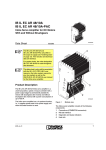
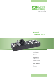
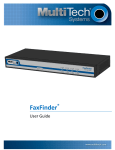
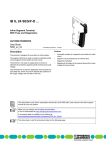
1
IB IL DC AR 48/10A (-2MBD-PAC)
Inline Servo Amplifier for DC Motors With
Brushgears
AUTOMATION
Data Sheet
6455_en_02
1
© PHOENIX CONTACT - 12/2007
Description
The Inline servo amplifier is designed for use within an Inline
station. It is a universal speed or torque controller with a
power output module for permanently excited DC motors
with brushgears with a power consumption of up to 450 W.
The Inline servo amplifier has a 4 quadrant function, i.e., it
supplies power back to the power supply unit when the
brake function is used.
1.1
–
–
–
–
–
1.2
Applications
The Inline servo amplifier is used under the following
conditions:
– Permanently excited DC motors with brushgears
– Nominal voltages of 12 V to 48 V
– Power consumption of up to 450 W
– Motor current of up to 10 A
Features
Diagnostic and status indicators
Can be used as a torque controller or speed controller
4 quadrant function
External brake chopper
Short-circuit-proof motor output
This data sheet is only valid in association with the IL SYS INST UM E user manual or the Inline system manual for
your bus system, as well as the user manual for the Inline servo amplifier UM EN IB IL DC AR 48/10A.
Make sure you always use the latest documentation.
It can be downloaded at www.download.phoenixcontact.com.
A conversion table is available on the Internet at
www.download.phoenixcontact.com/general/7000_en_00.pdf.
This data sheet is valid for all products listed on the following page:
IB IL DC AR 48/10A (-2MBD-PAC)
2
Ordering Data
Products
Description
Type
Order No.
Pcs./Pck.
Inline servo amplifier for DC motors with brushgears;
complete with accessories (connectors);
transmission speed of 500 kbps
IB IL DC AR 48/10A
2819286
1
Inline servo amplifier for DC motors with brushgears;
complete with accessories (connectors);
transmission speed of 2 Mbps
IB IL DC AR 48/10A-2MBD-PAC
2897677
1
Documentation
Description
Type
Order No.
Pcs./Pck.
"Inline Servo Amplifier for DC Motors With Brushgears" user manual
UM EN IB IL DC AR 48/10A
2699192
1
"Automation Terminals of the Inline Product Range" user manual
IL SYS INST UM E
2698737
1
"Configuring and Installing the INTERBUS Inline Product Range"
user manual
IB IL SYS PRO UM E
2743048
1
3
Technical Data
3.1
Housing Dimensions
4 8 m m
(1 .8 9 0 ")
1 6 6 m m
(6 .5 3 5 ")
8 5 m m
(3 .3 4 6 ")
6 4 5 5 A 0 3 1
General Data
Housing dimensions (width x height x depth)
48 mm x 85 mm x 166 mm
Housing material
PA 6.6; black, anodized aluminum
Heatsink material
Aluminum
Weight (typical)
460 g
Permissible temperature (operation)
-25°C to +55°C
Permissible temperature (storage/transport)
-25°C to +85°C
6455_en_02
PHOENIX CONTACT
2
IB IL DC AR 48/10A (-2MBD-PAC)
General Data (Continued)
Permissible humidity (storage/transport with unused interfaces
(standard packaging))
75% permanent, 85% occasionally
For a short period, slight condensation may appear on the outside of the housing if, for example, the module is brought into a closed room
from a vehicle.
Permissible air pressure (operation)
80 kPa to 106 kPa (up to 2000 m above sea level)
Permissible air pressure (storage/transport)
70 kPa to 106 kPa (up to 3000 m above sea level)
Permissible humidity (operation/storage/transport)
10% to 95%, according to EN 61131-2
Degree of protection
IP20 according to IEC 60529
Protection class
Class 3 according to VDE 0106, IEC 60536
Transmission Speed
IB IL DC AR 48/10A
500 kbps
IB IL DC AR 48/10A-2MBD-PAC
2 Mbps
Mechanical Requirements
Vibration test;
sinusoidal vibrations according to IEC 60068-2-6, EN 60068-2-6
2g load, 2 hours in each space direction
Shock test;
according to IEC 60068-2-27, EN 60068-2-27
25g for 1 ms, three shocks in each space direction
Free fall according to IEC 60068-2-32
1m
Power Supply
Status indicators
US LED
Connection method
2-pos. COMBICON connector
Supply voltage US
12 V DC to 48 V DC ±15%
Supply current
0 A to 10 A
Surge voltage shutdown
US > 60 V DC
Outputs
Number
1
Connection
1 permanently excited DC motor with brushgears
Connection method
3-pos. COMBICON connector with shield connection clamp
Output voltage
± Supply voltage US, maximum
Mean value 92% of US, maximum
Motor cable
2-wire, shielded
Continuous current
10 A, maximum
Starting current
10 A, maximum
Motor current limiting
0 A to 10 A (can be set via bus)
Maximum motor voltage
±65 V DC
Function
4 quadrant servo controller
Braking
Energy fed back to the power supply unit
(brake chopper may be required)
Minimum motor inductance
200 µH at US = 48 V DC
100 µH at US = 24 V DC
Cycle Time of Internal Digital Controllers
Speed controller
1 ms
Torque/current controller
250 µs
Electrical Isolation
Logic UL/I/O/motor
500 V AC test voltage
Pulse Width Modulation (PWM)
Clock frequency
6455_en_02
20 kHz
PHOENIX CONTACT
3
IB IL DC AR 48/10A (-2MBD-PAC)
Interfaces
500 kbps
Local bus
Inline potential distributor
2 Mbps
Inline potential distributor
Communications power UL
7.5 V DC (via potential distributor)
7.5 V DC (via potential distributor)
60 mA, typical
Current consumption at UL
45 mA, typical
Main voltage UM
24 V DC (via potential distributor)
24 V DC (via potential distributor)
Current consumption at UM
65 mA, typical
65 mA, typical
Conformance With EMC Directive 89/336/EEC and 2004/108/EC
Conformance is only ensured if the shielded motor cable is connected to the FE terminal and the module is connected to functional earth
ground via the DIN rail.
Noise Immunity Test According to EN 61000-6-2
Electrostatic discharge (ESD)
EN 61000-4-2
IEC 61000-4-2
Criterion B
6 kV contact discharge
8 kV air discharge
Fast transients (burst)
EN 61000-4-4
IEC 61000-4-4
Criterion B
Supply lines: 2 kV
Signal/data lines: 2 kV
Criterion A
Interfaces: 1 kV
Conducted interference
EN 61000-4-6
IEC 61000-4-6
Criterion A, test voltage 10 V
Noise Emission Test According to EN 61000-6-4
Noise emission of housing
EN 55011
Class A
Approvals
For the latest approvals, please visit www.download.phoenixcontact.com or www.eshop.phoenixcontact.com.
6455_en_02
PHOENIX CONTACT
4
IB IL DC AR 48/10A (-2MBD-PAC)
4
Typical Application of the Inline Servo Amplifier
B A
R D
R C
U L
S F
U S
L 1
A 1
D
A 1
D
L 4
A 1
D
L 1
A 2
L 2
R U N
E 3
E 1
L 3
F A IL
E 4
E 2
E 4
E 2
E 3
E 1
E 3
E 1
L 3
S F
A 2
A 2
L 2
R U N
F A IL
U M
L D
E 4
E 2
L 4
IB IL P O S 2 0 0
1
2
1
2
1
2
1
2
1
2
1
1
2
1 1
2
1
2 2
1 1
2
2 2
1
2
1
1
2
2
1
2
1
2
1
1 1
1 1
1 1
1
1 1
1 1
1 1
1 1
1 11
1 1 1
1 1
1
1
1
1
1 1
1
2
2 2
2 2
2 2
2 2
2 2
2 2
2 2
2 2
2 22
2 2 2
2 2
2
2
2
2
2 2
2
3
3 3
3 3
3 3
3
3 3
3 3
3 3
3 3
3 33
3 3 3
3 3
3
3
3
3
3 3
3
4
4 4
4 4
4 4
4
4 4
44 4
4 4
4 4
4 44
4 4 4
4 4
4
4
4
4
4 4
4
5 5
5
5 5
5
6 6
6 6
D C
5
6
5
6 6
P o s itio n in g C P U
B A
R D
R C
L D
U L
A 1
D
U S
S F
A 2
A x is 2
A 1
D
A 1
A 1
D
A 2
E 3
E 1
E 4
E 2
A x is 1 0
A 2
E 3
E 1
E 4
E 2
D
A 2
E 3
E 1
L 4
A x is 3
A 1
D
A 2
L 2
L 3
F A IL
E 4
E 2
A x is 1
L 1
R U N
E 3
E 1
U M
m o to r
6
E 3
E 1
E 4
E 2
E 4
E 2
IB IL P O S 2 0 0
1
2
1
2
1
2
1
2
1
11
2
2 2
1
2
1
1
2
2
1
2
1
2
1
2
1
2
1
2
1
2
1
2
1
2
1
1 1
1 1
1 1
1
1 11
1 1 1
1 1
1
1
1 1
1 1
1
1
1 1
1
1
1 1
1
1
1 1
1
2
2 2
2 2
2 2
2
2 22
2 2 2
2 2
2
2
2 2
2 2
2
2
2 2
2
2
2 2
2
2
2 2
2
3
3 3
3 3
3 3
3
3 33
3 3 3
3 3
3
3
3 3
3 3
3
3
3 3
3
3
3 3
3
3
3 3
3
4
4 4
4 4
4 4
4 44
4 4 4
4 4
4
4
4 4
4 4
4
4
4 4
4
4
4 4
4
4
4 4
4
5 5
5
4
5
6
6 6
6
P o s itio n d e te c tio n
L im it s w itc h
E n c o d e r
Figure 1
6455_en_02
L im it s w itc h
D C
m o to r
6 4 5 5 A 0 3 3
Typical application of the Inline servo amplifier
PHOENIX CONTACT
5
IB IL DC AR 48/10A (-2MBD-PAC)
5
Structure of the Module
4
3
2
1
Figure 2
6 4 5 5 A 0 0 1
Structure of the Inline servo amplifier
The Inline servo amplifier consists of the following
components:
1 Motor connection
2 Power supply connection
3 Diagnostic and status indicators
4 Heatsink
6455_en_02
PHOENIX CONTACT
6
IB IL DC AR 48/10A (-2MBD-PAC)
6
Local Diagnostic and Status Indicators
US
US
IB
+
TR
-
US
IB
+
-
ERR
TR
US
+
ERR
FE
IB
TR
US
ERR
MOTOR
6455B002
Figure 3
Des.
IB
TR
US
Local diagnostic and status indicators
Color
Green LED
ON:
Flashing:
0.5 Hz:
2 Hz:
4 Hz:
Red LED
ON:
Communications power present, bus not active
Communications power present, bus active, I/O error
Communications power present, terminal before the flashing module failed,
terminal after the flashing module not part of the configuration frame
Communications power not present, bus not active
PCP active
PCP messages being transmitted to the Inline servo amplifier
No transmission of PCP messages
Supply voltage of the power section
Supply voltage for the output module is more than 75% of the nominal voltage of
the power supply
Supply voltage for the output module is less than 75% of the nominal voltage of the
power supply
Error
An error has occurred (corresponds to bit 3 in the status word).
OFF:
The cause of the error can be read in the "ErrorCode" parameter (index 603Fhex).
No error
OFF:
Green LED
ON:
OFF:
Green LED
ON:
OFF:
ERR
6455_en_02
Meaning
Diagnostics
Bus active
PHOENIX CONTACT
7
IB IL DC AR 48/10A (-2MBD-PAC)
7
Terminal Point Assignment
as the desired speed/torque via Inline in the form of process
data (4 quadrant mode).
7.1
Power Supply Connection
A special feature of the Inline servo amplifier is that it can be
used to create simple speed-controlled drives using costeffective DC motors with brushgears, without the need for a
rotary encoder system (e.g., on the motor shaft).
1
+
-
2
Figure 4
6 4 5 5 A 0 0 3
Terminal point assignment of the power supply
connection (US)
Terminal Point
1
2
7.2
Assignment
US +
US –
Motor Connection
1
+
2
F E
3
6 4 5 5 A 0 0 4
Figure 5
Terminal point assignment of the motor
connection (MOTOR)
Terminal Point
1
2
3
8
Assignment
Motor +
Motor –
Functional earth ground
(FE)
This method relies on a particular aspect of the behavior of
DC motors: their speed changes in proportion to the supply
voltage. In this way the speed can be indirectly controlled
via the motor voltage.
In addition, the Inline servo amplifier uses an IxR controller,
which compensates for speed variations caused by the
changing load.
Operation, setting the operating mode, and
parameterization are compatible with the "DRIVECOM
profile 22" protocol.
The Inline servo amplifier has safety equipment, which
provides protection against:
– Overcurrent
– Surge voltage and undervoltage
– Overtemperature
– Short circuit between motor cables
– Short circuit to the power supply
The Inline servo amplifier is based on digital controllers. Its
task is to provide current and voltage values, which can be
used to directly operate DC motors with brushgears.
Since Inline jumpering cannot supply these high currents,
the Inline servo amplifier must be supplied externally with
12 V to 48 V and 0 A to 10 A.
The level of the current and voltage values depends on the
various functions that the Inline servo amplifier carries out in
the individual operating modes.
Function Description
The Inline servo amplifier is designed as an Inline terminal.
It can thus be easily operated in any control system and can
be used to create a distributed positioning control system
simply by mounting Inline positioning terminals side by side
(e.g., positioning CPUs, position detection terminals, and
other digital and analog output terminals).
For a description of the operating modes and the
parameters, please refer to the
UM EN IB IL DC AR 48/10A user manual.
Optical status and diagnostic indicators enable quick local
error diagnostics.
The following operating modes are possible:
– Speed control without IxR compensation (voltage
control)
– Speed control with IxR compensation
– Torque control (current control)
The Inline servo amplifier autonomously controls the speed
or the torque of the connected motor to the value specified
6455_en_02
PHOENIX CONTACT
8
IB IL DC AR 48/10A (-2MBD-PAC)
9
Programming Data/Configuration
Data
9.1
Local Bus
ID code
C3hex (195dec)
Length code
02hex (02dec)
Process data channel
32 bits
Input address area
2 words
Output address area
2 words
Parameter channel (PCP)
1 word
Register length (bus)
3 words
9.2
Other Bus Systems
For the programming data/configuration data of
other bus systems, please refer to the
corresponding electronic device data sheet
(e.g., GSD, EDS) at www.phoenixcontact.com.
6455_en_02
PHOENIX CONTACT GmbH & Co. KG • 32823 Blomberg • Germany • Phone: +49-(0) 5235-3-00
PHOENIX CONTACT • P.O.Box 4100 • Harrisburg • PA 17111-0100 • USA • Phone: +717-944-1300
www.phoenixcontact.com
9