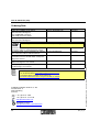
1
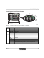
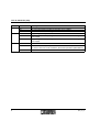
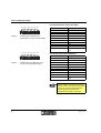
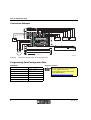
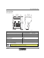
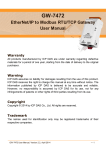
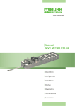
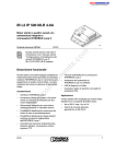
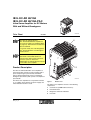
IB IL EC AR 48/10A
IB IL EC AR 48/10A-PAC
Inline Servo Amplifier for DC Motors
With and Without Brushgears
Data Sheet
6 9 7 6 A 0 0 0
03/2005
4
The IB IL EC AR 48/10A and
IB IL EC AR 48/10A-PAC only differ in
the scope of supply (see "Ordering Data"
on page 13). Their function and technical
data are identical.
For greater clarity, the order designation
IB IL EC AR 48/10A is used throughout
this document.
This data sheet is only valid in association
with the IB IL SYS PRO UM E user
manual or the Inline system manual for
your bus system as well as the
UM EN IB IL EC AR 48/10A user manual
for the Inline servo amplifier.
Product Description
3
The IB IL EC AR 48/10A Inline servo amplifier is a
universal position, speed or torque controller with a
power output stage for permanently excited DC
motors with brushgears (DC motors) and without
brushgears (EC motors) with a power consumption of
up to 450 W.
The Inline servo amplifier has a 4 quadrant function,
i.e., it supplies power back to the power supply unit
when the brake function is used.
6976_en_01
2
1
Figure 1
6 9 7 6 A 0 0 1
Module view
The Inline server amplifier consists of the following
components:
1 Connections (COMBICON connectors)
2 RS-232 interface
3 Diagnostic and status indicators
4 Heat sink
1
IB IL EC AR 48/10A (-PAC)
Features
Applications
–
–
–
–
–
–
The Inline servo amplifier is used under the following
conditions:
– Permanently excited DC motors with and without
brushgears
– Nominal voltages froM12 V to 48 V
– Power consumption of up to 450 W
– Motor current of up to 10A
Diagnostic and status indicators
Use as position, torque or speed controller
Inline device
4-quadrant function
External brake chopper
Short-circuit-proof motor output
Typical Application of the IB IL EC AR 48/10A
1
B A
R D
R C
L D
2
1
U L
S F
U S
2
1
2
1
A 2
L 2
L 3
2
1
2
1
1
2
1 1
2
2
3
D N
E 4
E 2
1
U P
E 3
E 1
L 4
2 4 V
D
A 1
D
L 1
R U N
F A IL
U M
5 V
Z
2 2
1
2
1
2
1
1 1
1 1
1 1
1
1 1
1 1
1 1
1
1
1 1
1
2
2 2
2 2
2 2
2 2
2 2
2 2
2 2
2
2
2 2
2
3
3 3
3 3
3 3
3
3 3
3 3
3 3
3
3
3 3
3
IN 2
+
IN 1
R E F
-
IB
T R
U S
E R R
U S
IN C 1
M 1
M 2
IN C 2 /H A L L
M 3
4 4
4
4 4
4 4
4
44 4
4 4
4
4 4
4
4 4
5 5
6
5
6 6
6
A x is 1
B A
R D
R C
1
U L
1
U M
2
1
2
1
1
1 1
1 1
1 1
2
2 2
2 2
2 2
3
3 3
3 3
3 3
2
IN 2
+
IN 1
R E F
-
IB
T R
U S
E R R
U S
IN 2
+
IN 1
4 4
M O T
M 3
E n c o d e r
2
IN 1
R E F
-
IB
T R
U S
E R R
IN 2
+
M 3
IB
T R
U S
E R R
IN C 1
M 2
IN C 2 /H A L L
M 3
F E
M O T
R E F
M 1
M 2
IN C 2 /H A L L
IN 1
U S
IN C 1
M 1
F E
M O T
L im it s w itc h
Figure 2
IN 2
+
U S
M 2
IN C 2 /H A L L
F E
4 4
U S
E R R
M 1
M 2
4 4
IB
T R
IN C 1
M 1
M 3
R E F
U S
IN C 1
4
A x is 1 0
A x is 3
A x is 2
U S
L D
2
F E
4
M O T
5
IN C 2 /H A L L
F E
M O T
L im it s w itc h
E C m o to r w ith H A L L s e n s o r
6 9 7 6 A 0 0 2
Typical application of the IB IL EC AR 48/10A
6976_en_01
IB IL EC AR 48/10A (-PAC)
Local Diagnostic and Status Indicators
IN 2
IN 1
IN 2
+
IN 1
R E F
R E F
IB
IB
T R
-
U S
E R R
U S
IN C 1
IN 1
IN 2
M 1
M 2
M 3
IN C 2 /H A L L
F E
M O T
R E F
IB
T R
T R
U S
E R R
U S
E R R
6 9 7 7 A 0 0 2
Figure 3
Des.
IN1
IN2
REF
IB
Local diagnostic and status indicators on the IB IL EC AR 48/10A
Color
Yellow LED
ON:
OFF:
Yellow LED
ON:
OFF:
Yellow LED
ON:
OFF:
Green LED
ON:
Flashing:
0.5 Hz:
2 Hz:
4 Hz:
OFF:
6976_en_01
Meaning
Limit switch 1
Input set
Input not set
Limit switch 2
Input set
Input not set
Home position switch
Input set
Input not set
Diagnostics
Bus active
Communications power present, bus not active
Communications power present, bus active, I/O error
Communications power present, terminal before the flashing module failed,
terminal behind the flashing module not part of the configuration frame
Communications power not present, bus not active
3
IB IL EC AR 48/10A (-PAC)
Des.
TR
US
Color
Green LED
ON:
OFF:
Green LED
ON:
Red LED
ON:
Meaning
PCP active
PCP messages being transmitted to the Inline servo amplifier
No transmission of PCP messages
Supply voltage of the power unit
Supply voltage for the output stage is more than 75% of the nominal voltage of the
power supply
Supply voltage for the output stage is lower than 75% of the nominal voltage of the
power supply
Error
An error has occurred (corresponds to bit 3 in the status word).
OFF:
The cause of the error can be read in the "ErrorCode" parameter (index 603Fhex).
No error
OFF:
ERR
4
6976_en_01
IB IL EC AR 48/10A (-PAC)
Terminal Point Assignment
Power Supply Connection (US)
1
Terminal Point
1
2
+
-
2
Figure 4
Assignment
US +
US –
6 4 5 5 A 0 0 3
Terminal point assignment for power
supply connection (US)
DC Motor Connection (MOT)
1
2
M 1
M 2
n . c .
F E
3
4
Figure 5
6 9 7 7 A 0 0 7
Terminal Point
1
2
3
4
Terminal point assignment for DC motor
connection (MOT)
Assignment
M1 (Motor +)
M2 (Motor –)
Not used
Functional earth ground
(FE)
EC Motor Connection (MOT)
1
2
3
4
Figure 6
M 1
M 2
M 3
F E
6 9 7 7 A 0 0 5
Terminal point assignment for EC motor
connection (MOT)
2
3
6976_en_01
Assignment
M1
M2
M3
Functional earth ground
(FE)
Limit Switch and Home Position Switch
Connections (IN2, IN1, REF)
1
Figure 7
Terminal Point
1
2
3
4
+ 2 4 V
IN
G N D
6 9 7 7 A 0 0 4
Terminal point assignment for limit
switch and home position switch
connections (IN2, IN1, REF)
Terminal Point
1
2
3
Assignment
+24 V
IN
GND
5
IB IL EC AR 48/10A (-PAC)
Incremental Encoder Connection (INC1)
1
2
3
4
5
6
7
8
9
1 0
6 9 7 7 A 0 0 6
Figure 8
Terminal point assignment for
incremental encoder connection (INC)
1
2
3
4
5
6
7
8
9
1 0
6 9 7 7 A 0 0 6
Figure 9
Terminal point assignment for Hall
sensor connection (INC2/HALL)
Terminal Point
1
2
3
4
5
6
7
8
9
10
Assignment
A
A
B
B
Z
Z
GND
+5 V
+24 V
Functional earth ground
(FE)
Hall Sensor Connection (INC2/HALL)
Terminal Point
1
2
3
4
5
6
7
8
9
10
Assignment
1+
1–
2+
2–
3+
3–
GND
+5 V
+24 V
Functional earth ground
(FE)
The INC2/HALL connection can also be
used to connect an incremental encoder.
In this case, connect the incremental
encoder using the terminal point
assignment of the INC1 connection.
6
6976_en_01
IB IL EC AR 48/10A (-PAC)
Function
The Inline servo amplifier is designed as an Inline
terminal. It can be easily operated in the most popular
control systems and can be used to create a
distributed positioning control system simply by
mounting Inline positioning terminals side by side
(e.g., positioning CPUs, position detection terminals,
and other digital and analog output terminals).
Optical status and diagnostic indicators enable quick
local error diagnostics.
The following operating modes are possible:
– Point-to-point positioning with position controller
(position feedback modes using an incremental
encoder or Hall sensors)
– Speed control (speed feedback using an
incremental encoder, Hall sensors or the motor
voltage)
– Torque control (current control)
– Homing
The IB IL EC AR 48/10A Inline servo amplifier carries
out positioning with position, speed or torque control
of the connected motor to the value specified as the
setpoint in the form of process data.
The Inline servo amplifier can be used to create
simple controlled drives using cost-effective DC
motors with or without brushgears. There is also
flexibility when choosing feedback for the individual
control functions. For example: In the "speed control"
operating mode for simple applications, there is no
need for a rotary encoder system.
On the one hand, this method relies on a particular
aspect of the behavior of DC motors: their speed
changes in proportion to the supply voltage. In this
way the speed can be indirectly controlled via the
motor voltage. In addition, the Inline servo amplifier
uses an IxR controller, which compensates for speed
variations caused by the changing load.
Operation, setting the operating mode, and
parameterization should be compatible with the
"DRIVECOM profile 22" protocol.
The IB IL EC AR 48/10A provides protection against:
– Overcurrent
– Surge and undervoltage
– Overtemperature
– Short circuit between motor cables
– Short circuit against the voltage supply
The IB IL EC AR 48/10A Inline servo amplifier is
based on digital controllers. Its task is to provide
current and voltage values, which can be used to
directly operate DC motors.
The Inline servo amplifier needs to be supplied
externally with 12 V up to 48 V and 0 A up to 10 A
because the Inline jumpering cannot supply these
high currents.
The level of the current and voltage values depends
on the various functions, which the Inline servo
amplifier carries out in the individual operating modes.
For additional information, please refer to
the UM EN IB IL EC AR 48/10A user
manual (Order No. 26 99 39 6).
RS-232 Interface
The RS-232 interface can be used to connect a PC
with startup and diagnostic software installed. This
interface also enables access to all drive parameters
and functions (see user manual).
Hall sensors can be used for speed and position
feedback when using EC motors. This also eliminates
the need for a rotary encoding system.
6976_en_01
7
IB IL EC AR 48/10A (-PAC)
Connection Example
IN 2
+
IN 1
R E F
IB
T R
-
IN
+ 2 4 V
+ 2 4 V
+ U
M 1
IN
IN
+ 2 4 V
1 -
S
IN C 1
2 +
U S
E R R
U S
M 2
M 3
IN C 2 /H A L L
F E
+ 5 V
+ 2 4 V
3 -
2 -
1 +
3 +
9
M O T
M
6 9 7 6 A 0 0 4
Figure 10
Connection example of EC motor with Hall sensor
Programming Data/Configuration Data
INTERBUS
Other Bus Systems
ID code
C3hex (195dec)
Length code
03hex (03dec)
Process data channel
48 bits
Input address area
3 words
Output address area
3 words
Parameter channel (PCP)
1 word
Register length (bus)
4 words
8
For the configuration data of other bus
systems, please refer to the
corresponding electronic device data
sheet (GSD, EDS) at
www.download.phoenixcontact.com.
6976_en_01
IB IL EC AR 48/10A (-PAC)
Technical Data
Housing Dimensions
8 3 .5 m m
(3 .2 8 7 ")
IN 2
+
IN 1
R E F
IB
T R
-
U S
E R R
U S
1 6 6 m m
(6 .5 3 5 ")
9 7 .2 m m
(3 .8 2 7 ")
IN C 1
M 1
M 2
M 3
IN C 2 /H A L L
F E
M O T
6 9 7 6 A 0 0 3
General Data
Order Designation
(Order No.)
Housing dimensions (width x height x depth)
Housing material
Heat-sink material
Weight
without connectors
with connectors
Permissible temperature (operation)
Permissible temperature (storage/transport)
Permissible humidity (operation)
Permissible humidity (storage/transport with unused
interfaces [standard packaging])
IB IL EC AR 48/10A
(28 19 25 7)
IB IL EC AR 48/10A-PAC
(28 19 58 7)
97.2 mm x 166 mm x 83.5 mm
PA 6.6; black, anodized aluminum
Aluminum
800 g
880 g
-25°C to +55°C
-25°C to +85°C
75% permanent, 85% occasionally
75% permanent, 85% occasionally
For a short period, slight condensation may appear on the outside of the housing if, for example,
the module is brought into a closed room from a vehicle.
6976_en_01
9
IB IL EC AR 48/10A (-PAC)
General Data (Continued)
Permissible air pressure (operation)
Permissible air pressure (storage/transport)
Degree of protection
Class of protection
80 kPa to 106 kPa (up to 2,000 m above sea level)
70 kPa to 106 kPa (up to 3,000 m above sea level)
IP20 according to DIN 40050
Class 3 according to VDE 0106, IEC 60536
Mechanical Requirements
Vibration test
sinusoidal vibrations according to IEC 60068-2-6;
EN 60068-2-6
Shock test
according to IEC 60068-2-27, EN 60068-2-27
Free fall according to IEC 60068-2-32
1m
Power Supply
Status indication
Connection method
Supply voltage US
Supply current
Surge voltage shutdown
US LED
2-pos. COMBICON connector
12 V DC to 48 V DC ±15%
0 A to 10 A
US > 60 V DC
Outputs
Number
Connection
Connection method
Output voltage
Motor cable
Continuous current
Starting current
Motor current limiting
Maximum motor voltage (feedback)
Function
Braking
Minimum motor inductance
10
2g load, 2 hours in each space direction
25g for 1 ms, three shocks in each space direction
1
1 permanently excited DC motor with or without
brushgears
4-pos. COMBICON connector
with shield connection clamp
± supply voltage US, maximum
Average up to 95% of US
2-wire, shielded (DC motor)
3-wire, shielded (EC motor)
10 A, maximum
10 A, maximum
0 A to 10 A (can be set via bus)
±65 V DC
4 quadrant servo controller
Energy fed back to the power supply unit
(brake chopper may be required)
200 µH at US = 48 V DC
100 µH at US = 24 V DC
6976_en_01
IB IL EC AR 48/10A (-PAC)
Encoder Types
Symmetrical Incremental Encoders
Encoder supply
Signal connection method
Signal voltage level
Common mode range: signal – ground
–
At 1 VPP voltage level
– At 6 VPP voltage level
Input frequency
Cable length (for shielded cable)
5 V DC or 24 V DC
A and A, B and B, Z and Z
1 VPP to 6 VPP
±2 V
±4 V
1 MHz, maximum
<30 m (to ensure conformance with EMC directive
89/336/EEC)
Asymmetrical Incremental Encoders
Encoder supply
Signal connection method
Signal voltage level
Input frequency
5 V DC or 24 V DC
A, B, Z
Low 0 V to 2 V, high 3.5 V to 27 V
–
500 kHz, maximum
At 4 V voltage level
– At 20 V voltage level
Cable length (for shielded cable)
Encoder Supply
5 V encoder supply
Voltage range
Short-circuit protection
Current carrying capacity
24 V encoder supply
Voltage range
Short-circuit protection
Current carrying capacity
100 kHz, maximum
< 30 m (to ensure conformance with EMC directive
89/336/EEC)
4.75 V to 5.25 V
Electronic and thermal
100 mA, maximum
19.2 V to 30 V
Electronic and thermal
100 mA, maximum
Cycle Time of Internal Digital Controllers
Position controller
Speed controller
Torque / current controller
1 ms
500 µs
250 µs
Electrical Isolation
Logic UL / I/O / motor
500 V AC test voltage
6976_en_01
11
IB IL EC AR 48/10A (-PAC)
Pulse Wide Modulation (PWM) (In Relation to the Motor Voltage)
Clock frequency
10 kHz to 50 kHz
Interfaces
Local bus
Communications power UL
Current consumption at UL
Main voltage UM
Current consumption at UM
RS-232
Inline potential distributor
7,5 V DC (via potential distibutor)
30 mA, typical; 120 mA, maximum
24 V DC (via potential distibutor)
100 mA, typical; 150 mA, maximum
Connection to startup and diagnostic software
Approvals
CE
UL
Yes
Applied for
Conformance With EMC Directive 89/336/EEC
Conformance is only ensured if the shielded motor cable is connected to the FE terminal and the
module is connected to functional earth ground via the DIN rail.
Noise Immunity Test According to EN 61000-6-2
Electrostatic discharge (ESD)
EN 61000-4-2
IEC 61000-4-2
Fast transients (burst)
Conducted interference
EN 61000-4-4
IEC 61000-4-4
EN 61000-4-6
IEC 61000-4-6
Noise Emission Test According to EN 61000-6-4
Noise emission of housing
EN 55011
12
Criterion B
4 kV contact discharge
6 kV air discharge
Criterion A
Supply lines: 2 kV
Signal/data lines: 2 kV
Criterion A, test voltage 10 V
Class A
6976_en_01
IB IL EC AR 48/10A (-PAC)
Ordering Data
Description
Inline servo amplifier for DC motors
with and without brushgears;
incl. COMBICON connectors
and shield connection clamps
Inline servo amplifier for DC motors
with and without brushgears
Order Designation
IB IL EC AR 48/10A-PAC
Order No.
28 19 58 7
IB IL EC AR 48/10A
28 19 25 7
Connector set consisting of seven COMBICON
connectors and three shield connection clamps
EC AR SW TOOL startup and diagnostic software,
incl. connection cable for RS-232 interface
Connecting cable for the RS-232 interface, for the
connection of the EC AR SW TOOL startup and
diagnostic software
"Inline Servo Amplifier for DC Motors With and
Without Brushgears" user manual
"Configuring and Installing the INTERBUS Inline
Product Range" user manual
IB IL ECAR-PLSET
28 19 56 1
EC AR CAB SW TOOL
28 19 54 5
EC AR DIAG CAB
28 19 73 6
UM EN IB IL EC AR 48/10A
26 99 39 6
IB IL SYS PRO UM E
27 43 04 8
© PHOENIX CONTACT 03/2005 Technical modifications reserved. TNR 90 18 14 4
The following connector set is needed for the complete fitting of the IB IL EC AR 48/10A:
Make sure you always use the latest documentation.
It can be downloaded at www.download.phoenixcontact.com.
A conversion table is available on the Internet at
www.download.phoenixcontact.com/general/7000_en_00.pdf.
PHOENIX CONTACT GmbH & Co. KG
Flachsmarktstr. 8
32825 Blomberg
Germany
+ 49 - (0) 52 35 - 3-00
+ 49 - (0) 52 35 - 3-4 12 00
www.phoenixcontact.com
Worldwide Locations:
www.phoenixcontact.com/salesnetwork
13
6976_en_01