1
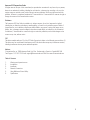
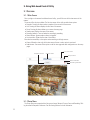
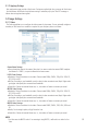
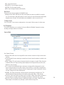
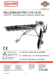
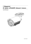
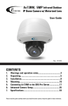
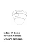
Annexxus 52C Instruction Manual Contents 1. Warnings and operation notes.............................................3 2. Introduction.......................................................................4 3. Installation............................................................................4 4. Network Connection.............................................................7 5. Using Web-based Control Utility........................................11 6. Specifications.......................................................................29 Annexxus 52C Camera User Guide All rights reserved. No part of this manual may be reproduced or transmitted in any form or by any means, electronic or mechanical, including, including but not limited to, photocopying, recording, or by any information storage or retrieval system, without the prior written permission of the copyright owner and the publisher. Annexxus is a registered trademark of i³ International Inc. i³ International Inc. reserves the right to change the contents of this manual without notice. Disclaimer The Annexxus x52C User Guide is provided as is, without warranty of any kind, expressed or implied, including but not limited to performance, merchantability, or fitness for any particular purpose. Neither i³ International Inc. nor its dealers or distributors shall be liable to any person or entity with respect to any liability, loss, or damage, caused or alleged to have been caused directly or indirectly by this information. Furthermore, i³ International Inc. reserves the right to revise this publication, and to make changes to the content at any time, without notice. FCC This device complies with part 15 of the FCC Rules. Operation is subject to the following two conditions: (1) This device may not cause harmful interference, and (2) this device must accept any interference received, including interference that may cause undesired operation. Address: i³ International Inc. • 780 Birchmount Road, Unit 16 • Scarborough • Ontario • Canada M1K 5H4 Tech Support: 1.877.877.7241 Email. [email protected] Web Site: www.i3international.com Table of Contents 1. 2. 3. 4. 5. 6. Warnings and operation notes Introduction Installation Network Connections Using Web-based Control Utility Specifications 2 1. Warnings and operation notes Thank you for purchasing an i³ Annexxus 52C camera. The Annexxus 52C User Guide: This version and all subsequent versions are products of i³ International Inc. Copyright of this manual belongs to i³ International Inc., and may not be reprinted or reproduced without prior written permission. If the system needs to be modified or repaired, a certified i³ International Dealer/Installer must be contacted. Otherwise, the system warranty will be voided. Should you have any problems or questions regarding our products, contact your local i³ International Dealer/Installer. Precautions Installation and serving should be performed only by qualified and experienced technicians to conform to all local codes and to maintain your warranty. WARNING! The use of CSA certified/ UL Listed Class 2 power adapter is required to ensure compliance. WARNING! To reduce the risk of fire or electric shock, do not expose the product to rain or moisture. When installing your Ax52C camera be sure to avoid: • excessive heat, such as direct sunlight or heating appliances • contaminants such as dust and smoke • strong magnetic fields • sources of powerful electromagnetic radiation such as radios or TV transmitters • moisture and humidity • areas with mechanical vibrations • fluorescent lamps or objects that reflect light • unstable light sources as this may cause flickering • temperatures below 10° Celsius or 14° Fahrenheit and above 50° Celsius or 122° Power Supply Ensure the supplied voltage meets the power consumption requirements of this camera before powering the camera on. Incorrect voltage may cause irreparable damage to the video camera and will effectively void the camera warranty. Cleaning •For maximum optical clarity, the camera or lens must remain clean. Use a soft, dry cloth to remove finger prints and dust from the dome cover. •Use a blower to remove dust from the lens. •Clean the body with a soft, dry cloth. If it is very dirty, use a cloth dampened with a small quantity of neutral detergent, then wipe dry. •Do not use volatile solvents such as alcohol, benzene, or thinners, as they may damage the surface finish. 3 Servicing To avoid electrical shock and to preserve the product warranty, DO NOT disassembles the camera. Refer servicing to qualified personnel only. 2. Introduction This 1080p network camera is equipped with a mechanical (ICR) day/night switch, making it ideal for 24/7 surveillance over a network. It suits any application where maximum image quality and efficient bandwidth usage is vital. At night and in low lighting conditions, its high sensitivity sensor ensures clear and noise free images. Meanwhile, crisp images also consume less bandwidth and storage. It also comes with various detection functions to keep you informed upon events. Other supported features include a micro SD/SDHC card slot, video out and two-way audio. 3. Installation 3.2 Package Contents The package includes these items: •Fixed Network Camera x1 •CD-ROM (User manual and IP Finder utility) x1 •Quick Start Guide x1 •2-pin Screw Terminal Block x1 •6-pin Screw Terminal Block x1 •CS-C Mount Adapter Ring x1 3.3 Hardware Overview 3.3.1 Dimensions 56mm(2.2”) 65mm(2.6”) 66mm (2.6”) 114mm (4.5”) 3.3.2 Part Names 1. Lens mounting ring: For mounting a C-mount or CS-mount lens. 4 2. Back Focus Control: Adjusts the distance between the back flange of the lens mounting and the image sensor. 3. Auto Iris lens connector: Supplies power and control signals to an auto-iris lens. 4. Tripod mount screw holes: Use these screw holes to attach a tripod mount. You can attach the mount to either the top or bottom side. (screw: 1/4”). 3.3.3 Rear Panel Reset Micro SD Card ALM-Out ALM-In 2 2 ALM-In 1 RS485 1 GND RS485+ Audio Out Power Audio In 3 4 5 6 Ethernet/PoE Video + ~ ~ DC 12V AC 24V 1. DC 12V/AC 24V: Connect the power terminals to a power supply. If using DC 12V power supply, make sure to connect the power connector to the correct ports (Red+/White–). 2. Video: To perform focus adjustments during the installation, connect the video port to a monitor. 3. Power LED: Is on when power is applied. 4. Audio In: Connect to a microphone 5. Reset: Using a pointed object, hold down the reset button for about 5 seconds to restart the camera, or hold down the reset button for longer than 5 seconds to reset the camera to the factory defaults. 6. Audio Out: Connect to a speaker. 7. microSD/SDHC Card Slot: Insert a microSD/SDHC card to the slot for recording and storage. 8. I/O: Connect your external devices, e.g., sensor and alarms to the corresponding I/O terminal block. The pins of the I/O terminal block controls the following signals: Pin Signal Connection Specification RS485+ Reserved. 1 RS485Reserved. 2 GND Ground (electricity) in electrical circuits. 3 ALM-Out Connect to device that triggers alarm signals. Max. load = 1A 4 Use an NMOS transistor with source connected to Max. voltage = +30V DC GND. If used with an external relay, a diode must be connected in parallel with the load to protect against transient voltages. ALM-IN 1 Connect to device that responds to alarm signals. High: +3.3 to 6V DC 5 Connect to GND or trigger input to activate. Low: +1V DC (max.) ALM-IN 2 Connect to device that responds to alarm signals. High: +3.3 to 6V DC 6 Connect to GND or trigger input to activate. Low: +1V DC (max.) 9. Ethernet/PoE: Connects to the LAN port of a standard 10Base/100Base-TX device, e.g., hub, switch or router. The LED indicators show the status as below: 5 LED Network Color Green PoE Orange Status On Off On Off Indication Network connection is established No network connection The camera power is supplied via PoE The camera power is not supplied via PoE 3.4 Installing the Lens Attach your lens onto the camera’s lens mounting ring. •CS-Mount lens: Attach the lens to the camera directly. •C-Mount lens: You must mount the supplied CS-C mount adapter ring first and then attach the CMount lens. If you are using an auto-iris lens, connect the auto-iris cable to the IRIS connector on the camera. 3.5 Mounting the Camera Attach a stand (not provided) to the camera and mount the camera to your intended location. Make sure to firmly attach the camera to a suitable flat surface. 3.6 Connecting the Cables 1. Optionally connect external input/output devices to the camera. 2. Optionally connect a speaker and microphone to the camera. 3. Connect the camera to a power source, using one of these options: • DC 12V or AC 24V: Connect to the power terminals on the on the rear panel. If using DC 12V power supply, make sure to connect to correct ports (Red+/White–). • PoE: Using an Ethernet cable, connect the LAN port to a PoE-capable network device. Power will be supplied through the Ethernet cable. 4. Optionally connect a video monitor if you want to perform focus adjustments during the installation. 3.7 Adjusting the View and Focus Adjust the focus controller, and zoom controller of the lens to get the best resolution. If needed, adjust the back focus to achieve the focus 6 4. Network Connection 4.1 Network Connection Types There are many different ways that you can connect the camera to your network, depending on your applications requirements. You should always set the camera’s network settings according to your network configurations. The following diagrams depict some typical applications with guidelines on network settings. For more information on network settings, always consult with your network administrator or ISP as required. Note: The LAN port of the camera supports auto MDI/MDIX (Medium dependent interface crossover) so there is no need to use cross-over cable. Type 1— Direct Connection to the Server or PC Directly connect the camera to a PC using a standard Ethernet cable. To extend the connection length, you should use a RJ-45 female/female coupler to connect two Ethernet cables together. To access the camera, the PC must be on the same network as the camera. The default IP address of the camera is a static one (192.168.1.30). Specify your PC’s IP address as 192.168.1. X (where X is a number between 2 to 254, excluding 30 and subnet mask as 255.255.255.0, to allow the server to directky access the Server or PC Type 2: Connecting Camera(s) to a Local Area Network (LAN) To add the camera(s) to an existing LAN, just connect the camera(s) to the hub or switch on your network. If you want to provide the camera power via the Ethernet connection, a PoE-enabled hub/switch is required. Assign an IP address to your camera following your network IP allocation policy. You can manually specify the IP address or allocate the IP address automatically using a DHCP server, if available on your network. This setup will enable monitoring and managing the camera via a web browser from a local PC or server. 7 4.2 Accessing the Camera for the First Time The camera comes with a web-based setup utility, allowing you to view the video of the camera and configure the camera for optimal use in your environment. To access the camera’s web-based control utility, you need a PC that meets the following requirements: •Operating System: Windows Vista® or XP •Browser: Internet Explorer Version 6.0 or later •CPU: Intel Pentium 4.2 GHz or higher •RAM: 512 MB or more Do the following to connect your PC to the camera: Step 1: Make the connection For initial setup purposes, connect one end of an Ethernet cable to the RJ45 connector of the camera and the other end to the LAN port on your PC. Step 2: Configure your PC’s IP address The camera uses a default IP address of 192.168.1.30 and subnet mask of 255.255.255.0. To have your PC on the same network with the camera, configure your PC’s IP settings as below: •P address: 192.168.1. X, where X is a number between 2 to 254, excluding 30. •Subnet mask: 255.255.255.0. Ignore all other settings and click OK. Step 3: Verify the connection between the PC and the IP Cam 1. Launch the Command Prompt by clicking the Start menu, Programs, Accessories and then Command Prompt. 2. At the prompt window, type ping x.x.x.x, where x.x.x.x is the IP address of the camera (the default is 192.168.1.30). If a message starting with “Reply from…” appears, it means the connection is established. 8 Step 4: Access the camera from IE browser Open a browser and enter the IP address of the camera in the URL field. The default is 192.168.1.30. When prompted to login, enter the user name and the password. (The defaults: admin, 1234). Note that the password is case-sensitive. 9 Upon successful login, you will see the live view screen shown as the example below: 10 5. Using Web-based Control Utility 5.1 Overview 5.1.1 Main Screen After you login to the camera’s web-based control utility, you will first see the live view screen of the camera. The screen is like the picture below: The live view screen of the utility provides these options: •Snapshot: Pressing this button takes a snapshot of the current live view screen. •Live: Pressing this button displays the live view of the camera. •Setup: Pressing this button allows you to access the setup page. •Camera name: Displays the name of the camera. •Recording Indicator: Turns red when the recording is proceeding. •Alarm Indicator: Appears when an alarm is triggered. •Live view video: Shows the live view of the camera. Note that the accessibility to the options varies according to the login account. •Viewer: Allowed to view only the live view screen. Access to other options is restricted. •Administrator: Can access all the options on the live view page and make configurations on the setup pages. Live view video Snapshot button Camera name Setup button Alarm Indicator Recording Indicator 5.1.2 Setup Menu The Setup options are categorized into five groups: Image, Network, System, Event and Recording. Clicking the name will expand its sub-menu. See the ensuing sections for more information. 11 5.1.3 Applying Settings Each configuration page provides a Save button. Settings are applied right after you press the Save button. And the browser will refresh to load the latest setting or otherwise pop up the “Save OK” message to indicate that settings have been applied. 5.2 Image Settings 5.2.1 Codec The Codec page allows you to configure the video streams for the camera. You can optionally configure a secondary or third stream to a resolution as required by your third-party device or software. Camera Name Settings •Enter a descriptive name of the camera. Note that if you want to make the camera ONVIF compliant (see Network > ONVIF ), no space is allowed in the camera name. H.264 Codec Settings •Resolution: Choose a resolution for the video. Choices include 1080p, SXVGA, 720p, XGA, SVGA, D1, 2CIF, VGA, and CIF. •Bit Rate: According to your bandwidth, specify a value for data transmission rate (kbps). Higher value gets higher video quality but consumes more bandwidth. •Frame Rate: Choose the intended frame rate, i.e., the number of frames to transmit per second. MPEG4 Codec Setting •Resolution: Choose a resolution for the video. Choices include 1080p, SXVGA, 720p, XGA, SVGA, D1, 2CIF, VGA, and CIF. •Bit Rate: According to your bandwidth, specify a value for data transmission rate (kbps). Higher value gets higher video quality but consumes more bandwidth. •Frame Rate: Choose the intended frame rate, i.e., the number of frames to transmit per second. MJPEG Codec Settings •Resolution: Choose a resolution for the video. Choices include 1080P, SXVGA, 720P, XGA, SVGA and D1. •Quality: Set the image’s quality to High, Normal or Low. •Frame Rate: Choose the intended frame rate, i.e., the number of frames to transmit per second. NOTE: 1. Live View uses the MJPEG codec. If no streaming is using MJPEG, it will result in no video for Live View. 12 NOTE: (cont.) 2. If MJPEG is selected for both the primary stream and the third stream, Live View will always display video using the third stream codec settings. Refer to the table below for selectable codec types for each stream: Streaming Combination Primary Secondary Codec Resolution Codec Resolution Codec OFF N/A D1 1080P OFF H264 VGA MPEG4 2CIF CIF OFF MJPEG OFF N/A SXVGA MJPEG 720P XGA D1 OFF SVGA H264 VGA D1 MPEG4 2CIF MJPEG CIF OFF 1080P OFF N/A MJPEG H.264 SXVGA 720P XGA SVGA D1 OFF H264 MPEG4 Resolution N/A N/A VGA CIF N/A VGA CIF N/A VGA CIF OFF N/A MJPEG VGA CIF OFF N/A MJPEG VGA CIF N/A D1 VGA 2CIF CIF Third Mirror Settings This option allows you to mirror or flip the video image if required. •OFF: Turns off this function. •HORIZONTAL: Flips the images horizontally. •VERTICAL: Flips the images vertically. •BOTH: Flips the images vertically and horizontally. Rate Control Choose a bit rate control to manage your bandwidth usage. •Variable Bit Rate (VBR): VBR keeps the video stream quality as constant as possible by varying bit rate. This mode ensures high quality image for motion scene and is often selected when image quality demands priority. However, this mode requires more bandwidth in order to vary the bit rate. 13 Mirror Settings This option allows you to mirror or flip the video image if required. •OFF: Turns off this function. •HORIZONTAL: Flips the images horizontally. •VERTICAL: Flips the images vertically. •BOTH: Flips the images vertically and horizontally. Rate Control Choose a bit rate control to manage your bandwidth usage. •Variable Bit Rate (VBR): VBR keeps the video stream quality as constant as possible by varying bit rate. This mode ensures high quality image for motion scene and is often selected when image quality demands priority. However, this mode requires more bandwidth in order to vary the bit rate. TV Output Stream Turn on this option if you connect an analog monitor to the camera’s Video connector for video output. 5.2.2 Exposure The Exposure page allows you to configure the Exposure Mode and Backlight Compensation settings according to the light conditions of the camera. Exposure Mode Auto Exposure Settings • Method: Select which area of the image will be used to measure the amount of light to achieve best exposure. • Center Weighted: Exposure metering is averaged over the entire frame but emphasis is placed on the central area. • Object Targeted: This option meters the exposure based on the targets you specify. When this option is selected, define your target by clicking squares displayed on the image and then press Save Spot Window to save the setting. • EV: In a scene with predominantly light or dark areas, the image will be underexposed or overexposed, causing an image to be too dark or bright. In such situations, you can adjust a compensation value to optimize the exposure. Decrease the value if images appear too light (overexposed). Increase the value if images are too dark (underexposed). • Max/Min. Exp: Select the maximum / minimum exposure time according to the light source. The selectable value will change according to the frequency setting under Image > Basic Settings. • Sensitivity: Select how sensitive the camera reacts to the light. A higher value enables the camera to be more sensitive to the light conditions and adjust the exposure in the shortest time interval. • Max Gain: Specify the maximum amount of amplification applied to the image. A high level of gain allows images to be viewable in very low light, but will increase the image noise. 14 Manual Exposure Settings • Exposure Time: Enter a desired exposure time. • Gain: Select a gain value from 0 to 16. A high level of gain allows images to be viewable in very low light, but will increase image noise. ICR Control The camera incorporates an IR cut filter. In ICR Control you can specify how the camera switches between color and black/white modes. • Auto: Allows the camera to automatically switch between color and black/white modes. • Forced B/W: Forces the camera stay in black/white mode at all times. • Forced Color: Forces the camera stay in color mode at all times. • External: Enable this option if an external alarm input device is connected to control the IR cut filter. • Alarm: Set alarm input as 1 or 2 according your actual connection. • Active: Select (electricity) current status as high or low to define active status. BLC (Backlight Compensation) The Backlight Compensation function allows you to provide the optimal exposure of subjects under back light circumstances. • OFF/ON: Choose to enable or disable the BLC function. • BLC area setting: BLC area refers to the dark area where more details are expected. Define your BLC area by clicking squares displayed on the screen and then press Save BLC Window to save the setting. Digital Wide Dynamic Range 15 When there are both very bright and very dark areas simultaneously in the field of view, you can enable Digital Wide Dynamic Range (WDR) function. It optimizes an image to ensure that dark areas are more visible while retaining details in bright areas. • Level: Depending on the contrast/dynamic range of a scene, you can select different level of WDR. Higher level of WDR suits for higher contrast/dynamic scene. If you select Auto mode, the camera will automatically adjust the WDR level by itself depending on the light of the scene. 5.2.3 White Balance Select a white balance mode according to external light condition for the best color temperature. • Auto White Balance: Use this option when there is no special lighting in the environment. The camera will automatically adjust the color temperature according to the light conditions and the sensitivity you specify. The higher the sensitivity, the faster the adjustment. If the lighting conditions change frequently, select a lower sensitivity to prevent the camera from frequently changing white balance. • Manual White Balance: With any special light in the environment, you can use this option to manually adjust the red, green and blue channels, which are mostly affected by the special light. For example, if the red color is too bright, then you should lower the R Gain value. 5.2.4 Basic Setting The Basic Setting allows you to specify a frequency and adjust the basic image settings to optimize your video image. 16 • Frequency: Select an appropriate frequency to reduce the flicker on the image. “50 Hz” and “60 Hz” are provided Frequencies settings will affect the Max. Exposure and Min. Exposure settings underImage > Exposure. • TV System: Displays the current video standard: NTSC or PAL. This setting cannot be changed via web interface. • Brightness: Adjust the image brightness level. • Contrast: Adjust the image contrast level. • Saturation: Adjust the image saturation level. • Sharpness: Adjust the image sharpness level. • Default All Image parameters: Pressing this button will restore all the image settings to the defaults. 5.2.5 Smart Encoding On the Smart Encoding page you can specify a specific region of the video as more important, i.e., a region of interest (ROI). When a ROI is specified, the camera will assign a higher number of bits to the ROI area to deliver better video quality than non-ROI areas. NOTE: The Smart Encoding function is only available when H.264 is selected for one of the streams. Basic Setting To define a smart encoding area, click and drag your mouse on the image to define the region of interest and click Save Window to save the region. Click anywhere on the image to cancel the current defined area. • Mode: Select Fixed ROI to enable smart encoding function. • Priority: Select a priority level for the ROI. Basic Setting To define a smart encoding area, click and drag your mouse on the image to define the region of interest and click Save Window to save the region. Click anywhere on the image to cancel the current defined area. • Mode: Select Fixed ROI to enable smart encoding function. • Priority: Select a priority level for the ROI. 5.2.6 Smart Focus 17 In addition to observing the live view image to see if focus is achieved, you can also enable Smart Focus to help you verify if focus is locked. If this function is enabled, whenever focus is achieved, the focus window turns green. Basic Settings To focus on a desired subject using the Smart Focus function: 1. Click on the subject that you want to focus on and then click Save Window. 2. Check the Smart Focus Enabled box. This will turn the smart focus indicator to red. 3. Use the focal length and focus controls to optimize the focus. When focus is achieved, the indicator turns green. 5.2.7 Privacy Zone Privacy Zone allows you to mask sensitive areas of the image for privacy protection. If enabled, it will mask the live view and the recorded video clips/JPEG files. To turn on the privacy zone function: 1. Click and drag your mouse on the image to define the region to be masked and then click Save Window. 2. Select ON to enable Privacy Zone. This will turn the masked area to black. 18 5.3 Network 5.3.1 Basic • DHCP: If there is a DHCP server on the network and you enable this option, the server will automatically assign an IP address and related information to the camera. NOTE: If there is no DHCP server on your network or you prefer to manually assign an IP address to the camera, leave the DHCP checkbox blank. • IP Address & Subnet Mask: If the DHCP function is not enabled, you have to assign an IP address with the subnet mask to the camera. • Default Gateway: Enter the IP address of the gateway if required. Please contact your network administrator to ask whether or not you need to set up the gateway. • DNS: Enter the IP address of a DNS server. If you enter a domain name instead of an IP address in server-related fields, e.g., FTP, SMTP or NTP server, then the camera will need a DNS server to translate domain names into an IP address that is actually used for communication on the Internet. • HTTP Port: Use the standard HTTP port number 80 or alternatively specify another port number between 1025 and 65535. If you choose to use a non-standard port, and the camera on the LAN is to be accessible from the Internet, then you must configure your router/firewall to forward incoming HTTP request to that specified port (via NAPT/port forwarding settings). • MAC: Display the MAC address of the camera. Each camera comes with a unique MAC address, which is indicated on the product label. It helps you to identify which camera is currently accessed, particularly when multiple cameras are connected to your network. 5.3.2 NTP If you want the camera to synchronize its time clock with an NTP (Network Time Protocol) sever, configure the NTP server settings here. 19 • NTP Server: Enter the IP address or the domain name of the NTP server to synchronize with. • Time Zone: Select a time zone in which the camera is located. • Automatically Adjust for Daylight Saving Time Changes: Check to apply the daylight saving time automatically. 5.3.3 ONVIF ONVIF is a standard that ensures interoperability between IP-based physical security products regardless of the manufacturers. This camera is ONVIF compliant and you can configure whether the camera can be found by other ONVIF compliant products and the related settings. Basic Settings • Discovery via ONVIF: Check the box if you want the camera to be found by other ONVIF compliant devices in a network, e.g., an ONVIF compliant NVR. • Accept command/functionality outside of Discovery capability: If checked, the camera is allowed to accept commands from ONVIF compliant device thus changing the camera’s functionality. • User Authentication: If an ONVIF compliant device needs authentication for communication, enable this option. 5.4 System 5.4.1 Date and Time Current Time Displays the current date and time of the camera. Date and time will be updated after you configure new settings in the New Time section and click Save to apply the settings. New Time You can set the camera time by one of the following methods: • Set Manually: Manually enter the camera’s date and time settings in the given fields. • Synchronize with Computer Timer: Use this option to synchronize the camera’s date and time with the computer timer. 20 • Synchronize with NTP Server: Use this option to synchronize the camera’s date and time with an NTP (Network Time Protocol) server, which can be configured under Network > NTP. • Date Format: Allows you to specify a desired date format. 5.4.2 Time Stamp The Time Stamp function allows you to overlay the date and time stamp on the video. When enabled, the recorded video will be displayed with the date and the time. • Enable Date and Time Stamp: Check this box to enable the date and time stamp on images/video clips; to disable this function, uncheck the box. • Date Format: Select the desired date format for the time stamp. 5.4.3 Firmware Current Version Description: Displays the current version of the firmware. Specify the Firmware to Update: This function is designed to update the firmware of the camera. To perform the firmware upgrade, follow these parameters: • Keep the network connected during the update process. • DO NOT turn off or restart the camera during the firmware update process. To update the firmware: 1. Click the Browse button to locate the firmware file. 2. Click the Update button to start update. 3. When prompted, click OK to proceed. 21 4. Wait about 20~60 seconds until the file is successfully updated. Once the update is completed, the browser will show a message reads “Firmware update successful”. Then it will take 60 seconds to restart the camera. 5. The utility will automatically go back to live view screen after firmware has been updated successfully. You can also perform these tasks on the Firmware page: • Restart camera: Restart the camera. This will cause all streams to disconnect. • Factory Default: Reset all of the camera settings to the defaults, except network settings. After you confirm to reset, the camera will reset and restart automatically. When complete, you will return to the live view page. • Hardware Factory Default: Reset all of the camera parameters to the defaults, including the network settings. 5.4.4 Language The Language drop-menu allows you to change the language of the web interface. Supported languages include English, Spanish, Italian, Simplified Chinese and Traditional Chinese. Click Save to apply the language setting, and the browser will automatically refresh to reflect the change. 5.4.5 Log This page displays detailed information about the camera’s operations and activities, including all the login and alarm records. 22 5.4.6 Audio • Audio Receiving: If a microphone is connected to the camera, you can select ON to allow the camera to record the audio and transmit to your PC. This enables the camera to pick up sounds in the background. • Audio Playing: If a speaker is connected to the camera, you can select ON to allow the camera to play the audio transmitted from your PC. This enables you to speak to the person(s) around the camera. • Audio Volume: Allows you to adjust both the audio playing and recording volume of the camera. Using the two-way audio function Note that the two-way audio function is only active in the live view page using the web browser. To use the two-way audio function: 1. Make sure a speaker is connected to the Audio Out port and a microphone is connected to the Audio In port of the camera. 2. Enter System > Audio and enable both the Audio Receiving and Audio Playing functions. Then adjust the audio volume to the desired level. 3. To access the two-way audio streams: 4. Make sure your computer is connected to a microphone and speaker. Enter the live view page of the web-based utility. 5. Speak into the microphone and the person(s) around the camera should hear your voice. 6. When people around the camera are talking to you, you should hear them from the speaker that is connected to the computer. 5.5 Event When an event occurs, it triggers an alarm and the camera will take a pre-defined action, e.g., sending a recorded video clip or JPEG files to a designated server. With this camera, an event can be triggered by external alarm devices or the camera’s detection mechanism, including motion, blur, audio and Ethernet detection. 23 NOTE: 1. When there is more than one recording to be carried out at the same time, the scheduled video recording takes top priority, followed by the recording triggered by an Ethernet disconnection and lastly the recording triggered by other events. 2. Only one event will be handled at a time. If an event is already triggered, other event will be logged to the system but no action will be taken. 5.5.1 Motion Detection When the Motion Detection is enabled, the camera detects motion under a pre-specified condition within a designated area. When motion is detected, the camera will generate an alarm and then take a specified action. Note that to use the motion detection function, the following two conditions must be met: 1. You must select MJPEG codec for one of the streams to enable the live view. 2. You must select H.264 or MPEG4 codec for one of the streams to process the motion detection. Configuration • Motion Sensitivity: Specify the sensitivity to moving objects before the camera triggers an alarm. The higher the sensitivity, the slighter the movement is required to set off an alarm. You can alternatively select User Define and enter a value from 1 to 100 in the Customized Threshold field. When the motion within a specified area exceeds the threshold, an alarm will be triggered. Select OFF to disable the motion detection Motion Area Setting • Motion area setting: Click target squares displayed on the screen to define detection areas; once configured, click Save Motion Area to save settings. Action Specify the action to be taken when an alarm is triggered upon motion detection: • OFF: No action will be taken, but an alarm will be logged. • FTP: Recorded video clips/JPEG files will be uploaded to the FTP server when alarm is triggered. • SMTP: Notification email with the recorded JPEG files attached will be sent to the SMTP server. • SD Card: Recorded video clips will be saved to the SD card when the alarm is triggered. 24 5.5.2 External Alarms If external alarm devices, e.g., sensors and alarms, are connected to the camera’s alarm input/output, the following settings must be made: Configuration • Setting: Enable the Alarm I/O that is connected with the respective external alarm device. • Level: Set the (electricity) current as low or high to define the active state. Action Specify the action to be taken when external alarm is triggered: • OFF: No action will be taken, but an alarm will be logged. • FTP: Recorded video clips/JPEG files will be uploaded to the FTP server when alarm is triggered. • SMTP: Notification email with the recorded JPEG files attached will be sent to the SMTP server. • SD Card: Recorded video clips will be saved to the SD card when the alarm is triggered. NOTE: To perform a video recording, you must select MJPEG codec for one of the streams. 5.5.3 Blur Detection With the Blur Detection enabled, when the camera detects incidents that make video image blur, e.g. redirection, blocking or defocusing, the camera will generate an alarm and then take a specified action. NOTE: Note that to use the blur detection function, the following two conditions must be met: 1. You must select MJPEG codec for one of the streams to enable the live view. 2. You must select H.264 or MPEG4 codec for one of the streams to process the motion detection. 25 Configuration • Blur Detection: Select Enable to enable Blur Detection; select Disable to disable this function. • Sensitivity: You can alternatively customize the camera’s sensitivity to a blur. The camera will judge whether it has been tampered based on the sensitivity threshold specified. Action • OFF: No action will be taken, but an alarm will be logged. • FTP: Recorded video clips/JPEG files will be uploaded to the FTP server when alarm is triggered. • SMTP: Notification email with the recorded JPEG files attached will be sent to the SMTP server. • SD Card: Recorded video clips will be saved to the SD card when the alarm is triggered. 5.5.4 Audio Detection With the Audio Detection enabled, when the camera detects any sound, the camera will generate an alarm and then take a specified action. Configuration • Audio Sensitivity: Specify the camera’s sensitivity level to the audio signal. The higher the sensitivity, the lower the volume is required to set off an alarm. When set to OFF, the audio detection is disabled. Action Specify the action to be taken when an alarm is triggered upon audio detection: • OFF: No action will be taken, but an alarm will be logged. • FTP: Recorded video clip will be uploaded to the FTP server when the alarm is triggered. • SMTP: A notification email attached with the recorded video clip will be sent to the SMTP server. • SD Card: Recorded video clip will be saved to the SD card when the alarm is triggered. NOTE: To perform a video recording, you must select MJPEG codec for one of the streams. 5.5.5 Ethernet Detection With Ethernet detection enabled, when the camera detects an Ethernet disconnection, the camera will generate an alarm and then take a specified action. Configuration • Trigger an Alarm When Ethernet is Disconnected: Select whether to disable/enable this function. Action Specify the action to be taken when an alarm is triggered upon audio detection: 26 • OFF: No action will be taken, but an alarm will be logged. • SD Card: Recorded video clips will be saved to the SD card in AVI format when the alarm is triggered. NOTE: Regardless of your settings in Recording > SD card, when an Ethernet disconnection is triggered, the video clip recording will always be saved in AVI format. 5.5.5 Event Management Basic Setting • Alarm Duration: Specify the duration of the alarm when an event is triggered. • Alarm Reset: Use this button to stop the current alarm and to restart event detection again. 5.6 Recording Recording allows you to configure recording-related settings 5.6.1 Settings – Video Clip Configure the duration and format of video to be recorded when an alarm is triggered. Basic Settings • AVI Duration: Select video duration. • AVI Format: Select a desired video format. Available formats depend on the primary and the secondary streaming codec/resolution settings. 27 5.6.2 SD Card Storage Format Selection Storage Setting • File Format: Specify the format of the video to be saved to the SD card when an event is triggered. • Capacity/Usage: Shows the card capacity and the space usage percentage. • SD Card Format: Use this button to format the SD card. This option is not available if an SD card has not been inserted in the camera. • SD Card Unmount: Click this button before safely removing the SD card. This option is not available if an SD card has not been inserted in the camera. • SD Card Overwrite: Select ON to enable overwriting once the storage is full. 28 6. Specifications Image Sensor Image Compression Method Frame rate and resolution Lens Shutter Time Audio Alarm Day/Night Mode Minimum Illumination Video Port Video Output Image Enhance Digital WDR Privacy Zone Intelligent Video Alarm Detection Alarm Event Image Orientation Bit Rate Mode Local Storage Memory Card SD Card Overwrite SD Card Store Category Power supply Power Requirement Power Connector Power Consumption (Max.) Environment Operating Temperature Operating Humidity Storage Temperature Regulatory29 Image System F1/2 2 MP Image Sensor Optimized For Low-Light Performance Triple Streaming : H.264 / MPEG4 / Motion JPEG 30 fps (NTSC) and 25 fps (PAL) in 2MP Full HD 1080p(1920x1080) Lens Moutn: CS Mount; Adjustable Lens Back Focus Electric Range from 1/10000s to 1/3.75s Selectable (60Hz);Range from 1/10000s to 1/3.125s Selectable (50Hz) Two-Way Mono Audio, Full-Duplex, G.711 PCM 8kHz External Input Mechanical (ICR) D/N Control; Auto/ Forced BW/ Forced Color/ External TBD Lux @10IRE; Lux @50IRE (F1.2,Shutter Speed: 1/15sec) BNC x 1, 1.0Vp-p, 75 ohm NTSC: 720 X 480 @30fps;PAL: 720 X 576 @25fps Exposure Mode: Auto/Manual White Balance: Auto/Manual Backlight Compensation: 5x5 zones Selectable Sharpness, Saturation, Brightness, Contrast: 255 Levels Feature Brief Yes; 5 Levels Yes; Customized Threshold Privacy Zone Ethernet Detection/ Event Management Motion Detection: 5 x 5 Zones, 5 Level or Customized Threshold External Input File Upload via FTP and SD Card Notification via email, HTTP and TCP External Output Activation Video and Audio Recording to SD Card Mirror, Flip Primary Stream Bit Rate control: CBR/VBR Micro SD/ Micro SDHC Card up to 32 GB Yes Alarm / Motion / Schedule/ Un-Interrupt Recording DC 12V & AC 24V ± 10% / PoE (IEEE 802.3af) 2-pin Terminal Block 5W (TBD) -10ºC ~ 50ºC (-14ºF ~ 122 ºF) 10~ 90% RH -20ºC ~ 60ºC (-4ºF ~ 140 ºF) CE, FCC, RoHS Ethernet Internet Protocol Browser Alarm Port Audio In/Out Reset Network Port RS-485 Port Dimensions(LxWxH) Weight Intelligent Video Network 10Base-T/100Base-TX Ethernet Connection for LAN / WAN, RJ-45 IPv4, TCP/IP, UDP, HTTP, SMTP, DNS, DHCP, NTP, FTP, RTP, RTSP, ICMP, or UPnP IE Browser 6.0 or Above I/O connector Terminal Block 2 In / 1 Out 3.5mm Phone Jack 1 In / 1 Out Within 5 sec For Rebooting System; More Than 5 sec For Loading Default RJ45 male connector Terminal Block Mechanism 114mm x 66mm x 65 mm (4.5” x 2.6” x 2.6”) 320g (0.70 lb) Without Lens Ethernet Detection/ Event Management 30