1
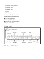
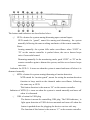
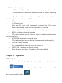
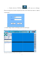
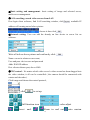
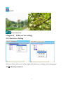
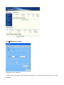
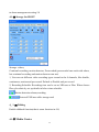
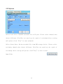
H.264 IP Camera Server
ES-IPS507
User Manual
V1.3
IPS507
Three channels wired and four channels wireless
video input server
IPS507WD
Four channels wired video input server
1
Welcome to use our IPS507 server
Please read the manual carefully before you use it, which will provide you a great
help. We do our best on improving products software, hardware function, and our
service quality.
Please contact the dealer once any doubt on using or product function are not the
same with the manual.
Contents
1.
Introduction
1.1 Usage
1.2 Declaration
2. Product description
2.1 Brief Introduction
2.2 Features
2.3 Packing list
2.4 Network requirements and software operation environment
2.5 Rear Panel
2.6 Keyboard Introduction
3. Operation
3.1 Installation
3.2 Image Window page
2
4.Server Management
4.1 Setup
4.1-⑴ Channel Parameters
4.1-⑵ Network System Settings
4.1-⑶ Hardware Management
4.1-⑷ Alarm Input/Output
4.1-⑸ Storage on IPS507
4.1-⑹ Talkback
4.1-⑺ Media Center
4.1-⑻ User Management
4.1-⑼
3322 DDNS
4.1-⑽
DynDNS
4.1-⑾ Email Notification
4.1-⑿ Monitoring
4.1-⒀ Update
4.2 Disconnect / Connect
4.3 Login Information
4.4 Talkback
4.5 Delete
5.Basic Setting
5.1 PC-Recording
5.2
Playback
3
5.3
Motion Detection
5.4
Alarm Setting
5.5 Format hard disk
Chapter 1
Introduction
IPS507 server uses the latest codec algorithm to transfer the analog AV signal
to digital by H.264 compression algorithm . Using TCP/IP protocol to send
low-bit-rate AV encoded data to remote PC by IP package, achieve the remote
transmission, monitoring and storage of AV signal to digital. It’s built-in Web
server,the users can use the standard IE browser on their PC or use specialized client
access to visit,watch images and control camera’s lens/PTZ from the front
end,achieve the omnibearing real-time surveillance.It can be widely used in building
control,road monitoring,industrial monitoring, large-scale remote monitoring,remote
care,online unicast and so on.
1.1 Usage
Help you correctly use IPS507 series products.
1.2 Declaration
Please setup the IPS507 server according to this manual strictly.The software
and hardware will continue upgrade and update.And the change will not give prior
notice,please take attention on the announcement from our website.
Chapter 2
Product Description
2.1 Brief Introduction
4
PS507 server is designed as an embedded control solutions for IP network
video and data surveillance.Using the faster computing speed DSP chipset and the
latest H.264 codec algorithm, really achieve the low-rate stream high definition.Every
frame on CIF is only 1.0KB to 1.5KB. Specially suitable for network transfer.The
max transmission speed is up 25fps(PAL)/30fps(NTSC)
IPS507 is a multi-use IP camera server. Besides providing 3 channels wired AV
input,4 channels wireless 2.4G AV input and network port, it also have 1 channel
local AV output and RS485 controlling port.
IPS507 has in-built Web server, stable and reliable system operation.Visit remote
images by specialized client port and IE browser.Support multiple network
type,include dynamic IP and static IP/PPPOE,to realize the function of image and
sound transfer on network. It also support the function of talkback, multi-linkage
alarm, motion detection and other advanced function.
5
2.2 Features
Model
3 channel wired channels A/V
4 channel wireless channel
inputs
(2.4GHz) A/V inputs
Yes
Yes
Yes
Yes(4wired)
NO
NO
IPS507
IPS507WD
Local A/V outputs
¾ 3 way audio/video control: front panel, remote controller, remote PC.
¾ Real time remote surveillance of multi audio/video sources.
¾ Support both WAN(via ADSL MODEM) and LAN connection.Note:3G dial-up
connection is under developing.
¾ Real time video recording via local USB port or on remote PC.
¾ Playback history recording and picture on remote PC.
¾ Motion detection: automatic video capture or snap shot when motion is detected.
¾ External alarms input/output function: such as PIR motion detection, smoke
detector, gas alarm.
¾ PTZ remote control(L/R/UP/DOWN/F+/F-) via optional PTZ decoder.
¾ 3-level user management system: operator , administrator and super
administrator with different level of privileges.
¾ Image compression format: H.264
¾ Support DynDNS.org & Oray.net & 3322.org free Dynamic DNS service
¾ Support catalog server to alias a dynamic IP address
2.3 Parameters
Parameters setting
Image
Compression
H.264 format
Image resolution
PAL:D1(704x576)/HalfD1(704x288)/ CIF(352x288)/ QCIF
(176x144)
NTSC:D1(704x576)/HalfD1(704x288)/ CIF(352x288)/
QCIF (176x144)
Image
Transmission Rate
PAL:1-25fps,NTSC:1-30fps
6
Interface
for
Storage devices
Talkback port
AV input
AV output
Recording format
PTZ Control
Network interface
Network Protocol
Dimension
Software upgrade
Video playback
Security
Working
Temperature
Power supply
Power
consumption
1 USB ports(USB2.0 port for storage)
1 USB port ( USB port for audio)
3 channels wired,4 channels wireless at 2.4GHz
PC :4 channels.Local:1 channel
DAT
RS485
RJ-45/10-100 Base T
Support TCP/IP,UDP, ARP, HTTP, DHCP, FTP etc
205×130×47(mm)
Automatic upgrade with the included software
IPSClient software
Access rights setting: Super administrator giving the rights
according to the new user
0 – 50℃
DC 5V/3A
< 10W
2.4 Packing List
Open the package and check the items contained against the following list:
One IP Camera Server
One DC AC110~240 5V/3A Power Supply
One AV cable and one T568B standard network cable
One BNC/ AV adapter
One CD(IPS507 Driver)
One remote controller
One Audio to USB adapter
Contact us immediately in the case of any damaged or short of contents.
2.5 Network requirements and software operation environment
IPS507 series products support 10/100M self-adaptive network port, can connect
to 10/100M or 100/1000M self-adaptive network environment. Due to the 7 channels
video stream, please keep each device’s bandwidth above 2M to ensure the normal
operation.
Related equipment software can be run in the following Windows operation system
7
z Windows XP SP2 or above
z Windows 2000
z Windows 2003
z Vista
z Windows 7
Advise to use IE 6.0 or above browser
System configuration requirements:
●
CPU:2.4GHZ or above
●
Memory:512M or above
●
Network Card: 10-100M or above
●
Display Card: 128M
2.6 Rear Panel
2.7
Keyboard Introduction
8
The buttons and indicators are described as below:
①
GUD: a button for system arming/disarming upon external inputs
GUD stands for “guard”, armed for arming and disarming , the system
manually following the same working mechanics of the remote controller.
Notes:
Arming manually: the system falls under surveillance when “GUD” or
“D” on the remote controller is pushed down; the server buzzer beeps
twice if successful armed.
Disarming manually: In the monitoring mode, push “GUD” or “D” on the
remote controller again to disarm the system; and the server buzzer beeps
twice too.
Indicator for GUD⑾:It turns on when the system is armed and turns off when it is
disarmed manually.
② MTD: a button for system arming/disarming of motion detection
MTD stands for “motion guard”, meant for setting the motion detection
function to keep watch on the channels under surveillance, following
the same way as GUD.
This button function is the same as “B” on the remote controller.
Indicator of MTD ⑩: t turns on when the system is armed manually and turns off
when it is disarmed.
③ USB: a button for USB plug
The button is meant for controlling USB plug. The USB indicator⑨is
light upon detection of USB devices mounted and turns off when the
button is pushed down for plugging the devices out in a safe way.
The function of this button is the same as “C” on the remote controller.
9
CHS: Channel switching button:
CHS stands of “channels”, used to switch the local output channels. The
switch of wireless channels is synchronous with the remote monitoring
channels.
The function of this button is the same as “A” on the remote controller.
Indicator⑧: It turns on when press “CHS”.
④
USB port
USB port: 2 ports
First port: The server will automatically recognizes the USB devices,
lights when plugged in and went out when they are removed.
Second port: Earphone port for audio.Indicator is lighting when talking.
⑤
RUN: an indicator of normal operation
This indicator lights turn on when the system is under normal operation,
went out when reset。
⑥ NETWORK: an indicator of network status
This indicator lights turn on when the system network works normally.
⑦ POWER: a power indicator
It is constantly lights when the system is powered on.
⑧
GUD+USB : a indicator of return to default
Press those two keys above 5 seconds it will return to default.
Chapter 3
Operation
3.1 Installation
First, open the included CD; Second, ① Please double click the
driver
, install to your PC, it will have a icon on your PC
desk after successful installed.
10
② Double click the “IPSClient”
, it will come out a dialogue.
Please entering the user name and password after click. Default user name is “admin”,
no password.
③ Below image window will display upon successful login.
Software interface divides into 4 parts:
11
1
○
Video window
2
○
Basic
setting and management
3
○
LAN searching: search video servers from LAN
4
○
Network setting
3.2 Image Window page
①Video window : video display of the network video server, there shows data of
name, time, frame, server address under each channel.
1)Image function
12
C1 : Channel name, can be changed
Time :2009-9-1 21 :29 :24
IP address : shows WAN/LAN IP address or domain name
Speed : real transferring frames per second
2)Click image via right button to get follow function
Close :close present channel image
Record: record present channel. When recording, it has a red point coming out, but to
choose well saving path, more description in 5.1
Snapshot:Taking picture for present image, manage taken pictures:①text font ②text
position ③text format④text custom ⑤ saving path ⑥picture format and watermark
Audio out: Open audio out, a speaker icon will come out.
13
②Basic setting and management : basic setting of image and selected server,
multi-server management.
③LAN searching: search video servers from LAN
First login client software, find LAN searching window, click
, available IP
address will coming out as below picture:
choose it then click
.
④Network setting: User can add the already on line device to server list on
software.
Write all info as above picture and confirm by click
.
Name: can write whatever user want,
User and pass: device user and password
Addr: WAN IP address
Port: client software port, above 8080
⑤PTZ control:No matter which video server's video screen has been dragged into
the video window, it all can be controlled ( the camera should be connected with
rotator and decorder ).
Click image and choose the control protocol ,
, click
to set up.
full function icon
focus+ and-
color adjust
Zoom in and out
14
auto crusion
default。
Zoom function
Chapter 4
Video server setting
4.1 Video Server Setting
Select a on line video server in list, right click and choose settings, enter setting page.
4.1-⑴ Channel parameters
15
Name: name for each video channel
CBR: fixed stream( the WAN network speed will influence the fixed stream)
Mobile: set to show images in mobile phone or not
Resolution: for video images, there are 4 types:
⒈“D1(704×576)”
⒉“HalfD1(704×288)”
⒊“CIF(352×288)”
⒋“QCIF(176×144)”
Image FPS and quality: It has different quality in different image resolution. User can
adjust it according the video images.
Fixed stream and browse in mobile phone is the factory default setting. In order to get
better quality, please do not mark in each option, and adjust the image resolution,
stream, frame to get better image quality.
Notes: please save as defaulted after changed the settings, otherwise it will recall to
factory default setting when server power off or restart.
4.1-⑵ Network system setting
16
TV systems: PAL/NTSC
Name: name for server
Network type:dynamic IP/static IP/ PPPOE auto dial-up Internet access
Working port: used for remote client software browsing
web port: for web
MAC address: server MAC address
IP address: server address in LAN
Subnet Mask: set up comply with router
Gateway: set the gateway in LAN
DNS: Please fill the correct DNS(different place with different DNS address), please
inquire from local Service providers.
Refer to above information, setting in router, add IP address, setting port range
forward and DNS, then the IP server can be visited in WAN
17
4.1-⑶ Hardware setting
Output to local monitor
Auto: user can select auto-switch in monitor, as well as the switch time for each
channel.
18
Manu: select to display one channel by manual.
Notes: audio will output to monitor follow video(video and audio are in same
channel)
4.1-⑷ Alarm input/output
Input/output link
1、
Input: there are 4groups external sensor signals, with Nopen(Normal open) and
Nclose(Normal close) status.
2、
Relay output link: there are 4groupes Relay output.
For example, External sensor(PIR detectors, Smoke detectors and door magnet), the
default status is Nopen, then it must be Noclose in the software. When alarm sensor is
triggered, the nopen will change to nclose in relay, and send signal to external alarm
like speaker.
Buzzer alarm link: when alarm sensor is triggered, user can choose buzz link to alarm
or not.
Motion detection/relay link: when user need to enable this function, please set
external alarm equipment(ex: speaker). Notes: the motion signals, can be output to
any relay(to any external alarm equipment)
3、Completed all settings, please activate the motion detection setting in 5.3
4、PC audio alarm link, relative reminds in the images of client software, please refer
19
to alarm management setting 5.4
4.1-⑸ Storage On IPS507
Storage: videos,
Continual recording, motion detector, Prerecorded( prerecorded can work with others,
but continual recording and motion detector can not).
1, User can set different video recording types toward to the 4 channels, like disable,
continuous, motion and pre-record. Default to Disable and pre-record.
2, Recording Schedule. Recording time can be set as 24Hours or Plan. When choose
Plan, pls relatively set up details in below time schedule.
Motion detection alarm,recording
Detected USB moveable storage card
4.1-⑹ Talking
Enable talkback function(that is same function in 4.4)
4.1-⑺ Media Center
20
Server connected with media center, it’s easy for controlling. This function will be
update, can not work right now.
4.1-⑻ User management
There are 4 kinds of user
User: normal user, only can browse images.
Power User:can control some function keys
Admin: with all functions(can open or delete user, including power user.)
Default admin: with all functions(it can be revised password, but can't be deleted)
For example:
”user” user can not change the setting no matter Intentionally or unintentionally.
Therefore, “user” can run the files which had be proved, can not run most old edition
Application; For example, the network property and other important option can not
be changed. Even the virus infects computer, it won’t cause great damage to the
system
Power user has most of the management authority, of course it with some restrictions.
21
4.1-⑼ 3322 DNS
3322 DNS: China second level free domain name. Easy for user to apply a free
domain name. Then analyse IP server's IP address and port on router. To realize
internet browsing.
4.1-⑽ DYN DNS
There are many free domain names appliable. User need to apply a domain name, to
setup the ip addrees and port inside router, then it can access to Internet.
4.1-⑾ Email
22
Email receiving:please fill in one available email address.
Email sending:please fill in email address which support SMTP
Sender name:can be any name
SMTP server:sending email address need to support SMTP,and port means the SMTP server
port.
Verify information:please fill in the sender’s account and password
4.1-⑿ System Monitor
System monitor: To reboot the on line device.
4.1-⒀ Update
23
Update: application upgrade.
4.2 Disconnect
Disconnect the device to be on line, disconnected can be click to connect, set it to be
on line again.
4.3 Login Info
Login info, right click to read the server data, but can't be modified.
4.4 Talking
Right click to start talking with local device, same with 4.1-6
4.5 Delete
24
Right click to delete connected on line server on software.
Chapter 5
Basic Setting
To non-fixed device,you can set up the relative setting only if there has video in video
window)
5.1 PC recording
Select recording path: can select recording video in several partitions. After choose
well path, right click video which need to be recorded. A red point comeing out
means recording begins. Recording format is dat, when file is over 32M, it will build
a new file for recording automatically. It will repeat building new file untill the disc is
full.
25
5.2 Playback
Select Local File: Playback recorded file on PC port. Please select channel,then
choose different files(You can speed up the speed of reviewing).After setting
well,please click “Play”to start playback.
Select Server Data: Review recorded file from USB storage device. Please select
reviewing channel,then choose different files(You can speed up the speed of
reviewing).After setting well,please click”Play”to start review.
Demo:Click:
26
Choose recorded file then
press
OK
and
press
,you
can
set
the
reviewing
speed
by
click:
5.3 Motion Detection
Choose a video to set up motion detection first, double click to amplify picture. When
27
picture is amplified to big enough, motion menu will become black color from gray
color, then user can set its sensitive, choose area(can be 2 area in one picture) then
save it. Pls double click picture back to normal picture, motion detection begins.
Available motion detection recording,please refer to 4.1-(5) storage on server.
5.4 Alarm Setting
After set up motion detection and hardware alarm well, relate it to software alarm
setting. User can choose voice file.( can be a song or a word). Note, voice file can be
only .wav file. User also can set up auto re-connection when connection is broken.
5.5 User management and format disk
28
After format the moveable storage disk,it will become a storable video file system.
Steps of format:please format U disk on PC first(Note:please format the file system
of U disk to FAT32),then format again on IPSclient software and it will automatically
become DAT video file. ( Pls don't insert the U disk to server device but only plug
to PC for format)
Support mobile phone monitoring.
Demand:
Most of smart phone with JAVA software are workable.
Below is a list for suggestion:
NOKIA
S60 or above
S60 version , smart phone 3rd version.
Symbian OS v9.1 DP S60 3rd
Models: 3250 5500 N71 N73 N77 N80 N91 N92
E61
E61i
E62
E65
N93 N93i
E50
E60
N95
E51
E70
Symbian OS v9.2 DP S60 3rd FP1
Models:5700
E90
E66
6110N
6120C
6121C
6290
N76
E71
Symbian OS v9.3 DP S60 3rd FP2
Models:6210N 6220C N78 N96 5320xm 6650
Note: S40 2ed are not supportable.
Sony Ericsson
All smart phone like P and G serials, and also W serials.
MOTOROLA
Support WM(windows mobile)serial
HTC
29
N81
N82
windows mobile 5 and 6
Summary: Only if mobile phone support WM 5 or 6, or symbian s60 V2/V3/V5 are
compatible with our device. Relative mobile operation instruction is attached.
30


![Rii Mini [Bluetooth]](http://vs1.manualzilla.com/store/data/005730343_1-53cd9486bcc3b780c33a2a4f5175af21-150x150.png)