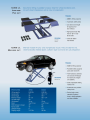
1
SAVE THIS MANUAL: You will need this manual for the safety warning and
precautions,
assembly,
operating,
inspection,
maintenance and cleaning
procedures, parts list and assembly diagram. Keep your invoice with this manual.
Write the invoice number on the inside of the front cover. Keep this manual and
invoice in a safe and dry place for future reference.
GENERAL SAFETY WARNINGS AND PRECAUTIONS
WARNING!
READ AND UNDERSTAND ALL INSTRUCTIONS BEFORE OPERATING
Failure to follow all instructions listed in the following pages may result in electric
shock, fire, and / or serious injury.
SAVE THESE INSTRUCTIONS AND READ THEM ENTIRELY!
1. KEEP WORK AREA CLEAN AND WELL LIGHTED
Cluttered, wet and dark work areas may invite accidents.
2. DO NOT OPERATE POWER EQUIPMENT IN EXPLOSIVE ATMOSPHERES,
SUCH AS IN THE PRESENCE OF FLAMMABLE LIQUIDS, GAS OR DUST.
Power equipment can create sparks which may ignite flammables.
3. KEEP BY STANDERS, CHILDREN, AND VISITORS AWAY WHILE OPERATING
Distractions can cause you to lose control.
4. STAY ALERT. WATCH WHAT YOU ARE DOING, AND USE COMMON SENSE
WHEN OPERATING POWER EQUIPMENT. DO NOT USE POWER EQUIPMENT
WHILE TIRED OR UNDER THE INFLUENCE OF DRUGS, ALCOHOL, OR
MEDICATION.
A moment of inattention while operating may result in serious personal injury.
5. RISK OF ENTANGLEMENT!
Dress properly. Do not wear loose clothing or jewelry. Contain long hair. Keep your hair,
5
clothing, and gloves away from moving parts. Loose clothes, jewelry, or long hair can
be caught in moving parts.
6. AVOID ACCIDENTAL STARTING. BE SURE THE POWER SWITCH IS OFF
BEFORE PLUGGING IN.
7. KEEP HANDS AND FEET CLEAR.
Remove hands and feet from any moving parts. Keep feet clear of lift when lowering.
Avoid pinch points.
8. DO NOT OVERREACH. KEEP PROPER FOOTING AND BALANCE AT ALL
TIMES.
Proper footing and balance enables better control of the lift in unexpected situations.
9. USE SAFETY EQUIPMENT.
Always wear approved safety impact eye goggles underneath a full face shield.
10. ONLY TRAINED PERSONNAL SHOULD OPERATE THIS LIFT.
All non-trained personnel should be kept away from work area. Never let non-trained
personnel come in contact with, or operate lift.
12. DO NOT USE LIFT IF THE POWER SWITCH DOSE NOT WORK PROPERLY.
Any equipment with a broken POWER SWITCH is dangerous and must be
repaired or replaced before operation.
13. DISCONNECT THE POWER CORD PLUG FROM THE POWER SOURCE
BEFORE MAKING ANY ADJUSTMENTS, CHANGING ACCESSORIES, OR
STORING THE LIFT
Such preventive safety steps reduce the risk of starting the equipment accidentally.
14. MAINTAIN POWER EQUIPMENT WITH CARE
Properly maintained equipment is less likely to fail and is easier to control. Do not
6
operate damaged equipment. Tag the damaged equipment “Do not use”
until repaired.
15. CHECK FOR MISALIGNMENT OR BINDING OF MOVING PARTS, BREAKAGE
OF PARTS, AND ANY OTHER CONDITION THAT MAY AFFECT THE
EQUIPMENT’S OPERATION. IF DAMAGED, HAVE THE EQUIPMENT SERVICED
BEFORE OPERATION.
Many accidents are caused by poorly maintained equipment.
16. USE ONLY ACCESSORIES THAT ARE RECOMMENDED BY THE
MANUFACTURER.
Accessories that may be suitable for one piece of equipment may become
hazardous when being used on another piece of equipment.
17. SERVICE MUST BE PERFORMED BY QUALIFIED PERSONNEL.
Service or maintenance performed by unqualified personnel could result in a risk of
injury.
18. WHEN IN SERVICE, USE ONLY IDENTICAL REPLACEMENT PARTS.
Follow instructions in the “INSPECTION, MAINTENANCE, AND CLEANING” section
of this manual. Use of unauthorized parts or failure to follow maintenance instructions
may create a risk of electric shock or injury.
19. GROUNDED TOOLS MUST BE PLUGGED INTO AN OUTLET PROPERLY
INSTALLED AND GROUNDED IN ACCORDANCE WITH ALL CODES AND
ORDINANCES. NEVER REMOVE THE GROUDING PRONG OR MODIFY THE
PLUG IN ANY WAY. DO NOT USE ANY ADAPTER PLUGS. CHECK WITH A
QULIFIED ELECTRICIAN IF YOU ARE IN DOUBT AS TO WHETHER THE
OUTLET IS PROPERLY GROUNDED.
If the tools should electrically malfunction or break down, grounding provides a low
resistance path to carry electricity away from the user.
20. DO NOT CHANGE THE PLUG IN ANY WAY.
7
Double insulated tools are equipped with a polarized plug (one blade is wider than the
other). This plug will fit in a polarized outlet only one way. If the plug does not fit fully in
the outlet, reverse the plug. If it still does not fit. Contact a qualified electrician to install
a polarized outlet. Double insulation eliminates the need for the three wire grounded
Power Cord and grounded power supply system.
21. AVOID BODY CONTACT WITH GROUNDED SURFACES SUCH AS PIPES,
RADIATOR AND RANGES.
There is an increased risk of electric shock if your body is grounded.
22. DO NOT EXPOSE POWER TOOLS TO RAIN OR WET CONDITIONS.
Water entering a power tool will increase the risk of electric shock
23. DO NOT ABUSE THE POWER CORD.
Never use the Power Cord to pull the plug from an outlet. Keep the Power Cord
away from heat, oil, sharp edges, or moving parts. Replace damaged Power
Cords immediately. Damaged Power Cords increase the risk of electric shock.
24. IMPROPERLY CONNECTING THE GROUNDING WIRE CAN RESULT IN THE
RISK OF ELECTRIC SHOCK.
Check with a qualified electrician if you are in doubt as to whether the outlet is properly
grounded. Do not modify the plug provided with the tool. Never remove the grounding
prong form the plug. Do not use the tool if the power cord or plug is damaged. If
damaged, have it repaired by a service facility before use. If the plug will not fit the outlet,
have a proper outlet installed by a qualified electrician.
25. IMPORTANT!
The lift is to be powered by a 110 volt, grounded, electrical outlet, and a 110 volt
grounded power cord. This wiring procedure must only be done by a qualified,
certified electrician.
26. DANGER!
8
Make sure you know the weight of the vehicle you are going to lift before using the Lift.
Do not exceed the maximum lift capacity (6000 pounds) for the Lift. Overloading the
Lift could cause personal injury and / or property damage. Be aware of dynamic
loading! If a weight suddenly falls onto the Lift. It may create for a brief instant an
excess load which may result in personal injury and / or damage to the vehicle and
Lift.
27. USE THE LIFT ONLY IN VENTILATED AREAS.
Carbon monoxide exhausted form running vehicle engines is a colorless, odorless
fume that, if inhaled, can cause serious personal injury.
28. MAKE SURE TO READ AND UNDERSTAND ALL INSTRUCTIONS AND SAFETY
PRECAUTIONS AS OUTLINED IN THE MANUFACTURER’S MANUAL.
All four Rubber Saddles (39B) of the Lift must be used when lifting a vehicle.
Always use the manufacturer's recommended lifting points.
29. DO NOT USE THE LIFT ON ANY ASPHALT SURFACES.
Make sure the Lift is used on a dry, oil/grease free, flat, level, concrete surface
capable of supporting the weight of the Lift. Do not use the Lift on concrete
expansion seams or on cracked, defective concrete.
30. ALWAYS EXAMINE THE LIFT FOR STRUCTURAL CRACKS,
bends, damage to the hydraulic hoses and electrical wiring, and any other condition
that may affect the safe operation of the Lift. Do not use the Lift even if minor damage
is detected.
31. IMPORTANT!
Operation (raising or lowering) of the Lift can be immediately stopped at any time by
releasing pressure on the POWER SWITH located on the Motor.
32. MAKE SURE
the oil tank is completely filled (approx. 2 gal.) with a premium quality hydraulic oil prior
to operation the Lift.
33. ALWAYS
9
allow at least two seconds after the Motor starts to raise or lower the Lift. Failure to do
so may cause the Motor to burn out.
34. PRIOR TO BEGINNING A JOB, MAKE SURE THE SAFETY LOCK ASSEMBLY
(36B) AND ITS SAFETY CATCHES ARE IN THE PROPER POSITION.
Never work underneath a vehicle without using additional safety support devices to
support the vehicle.
35. ALWAYS KEEP HANDS, FINGERS, AND FEET AWAY FROM THE MOVING
PARTS OF THE LIFT WHEN APPLYING OR RELEASING A LOAD.
Remain clear of the Lift when raising or lowering a vehicle.
36. USE EXTREME CAUTION WHEN APPLYING OR RELEASING A LOAD.
Never allow the load to suddenly release. Slowly and carefully apply and release the
load.
37. NEVER LEAVE THE LIFT UNATTENDED WHEN THE LIFT IS UNDER A LOAD.
38. MAKE SURE THE LIFT IS FULLY LOWERED BEFORE DRIVING A VEHICLE
ONTO THE LIFT.
Before driving a vehicle onto the Lift, position the Plates (42B) and Rubber Saddles
(39B) inward. Do not hit or run over the Plates and Rubber Saddles, as this could
damage the vehicle. Make sure the Lift is fully lowered before driving the vehicle off.
39. Should any weight component be removed from, or added to the vehicle,
use a jack stand (not included) to support the over balanced end
during the maintenance procedure.
Do not operate the Lift if the vehicle load tilts or binds during the up or down movement.
Always position the vehicle with the center of gravity midway between the Rubber
Saddles (39B).avoid excessive rocking of the vehicle while it is its raised position.
40. NEVER LIFT A VEHICLE WITH ANYONE INSIDE IT.
Do not allow others in the lift area while operating the Lift. Do not allow anyone
to ride on the Lift while it is being raised or lowered.
41. WHEN LIFTING A VEHICLE, RAISE THE RUBBER SADDLES (39B) SLOWLY
10
UNTIL THE RUBBER SADDLES SECURELY CONTACT THE VEHICLE’S
LIFTING POINTS.
Then, lift the vehicle to the desired working height. Always lift the vehicle high enough
for the Safety Lock Assembly (36B) to operate properly.
42. DO NOT USE THE LIFT AS A PERMANENT STAND FOR A VEHICLE.
Use the Lift only while making repairs. Then, immediately remove the vehicle form the
Lift.
43. BEFORE LOWERING THE LIFT, MAKE SURE TOOL TRAYS, STANDS,
AND ALL OTHER TOOLS OR EQUIPMENT ARE REMOVED FROM UNDER
THE VEHICLE.
44. MAKE SURE
To squeeze and hold in on the Brake Lever (13B) before attempting to lower the
vehicle. Do not release the Brake Lever until the Lift is lowered completely.
45. BEFORE REMOVING A VEHICLE FROM THE LIFT MAKE SURE THE
PLATES(42B) AND RUBBER SADDLES(39B) ARE MOVED INWARD TO
PROVIDE AN UNOBSTRUCTED EXIT.
In the general rated load state of the lift , noises should under 75dB
46. FORBID TEARING UP THE WARNING OR OTHER LABELS OF THE LIFT.
The warnings, precautions, and instructions discussed in this manual cannot cover all
possible conditions and situations that may occur. The operator must understand that
common sense and caution are factors which cannot be built into this product, but
must be supplied by the operator.
11
ASSEMBLY INSTRUCTIONS
DETERMINE THE PROPER LIFT LOCATION:
1. DO not use the Lift on any asphalt surface. Make sure the Lift is used on a dry, oil/
grease free, flat, level, concrete surface capable of supporting the weight of the Lift.
Do not use the Lift on concrete expansion seams or on cracked, defective concrete.
2. Make sure to check the desired location for possible obstructions such as a low ceiling,
overhead lines, adequate working area, access ways, exits, etcetera.
3. Make sure to allow a minimum space of 14 feet in front and behind the Lift to
accommodate all vehicles. Certain allowances should be made for special vehicle
requirements or unusual floor plans.
ATTACH THE POWER UNIT TO THE LIFT:
1. Locate the Hydraulic Pump in an area where it will be out of the way, is safe from
damage and weather, and where it can be easily reached to operate.
2. One end of the General Inlet Pipe (18B) has been pre-attached to the Lift by the
manufacturer. To attach the remaining end of the General Inlet Pipe to the
Hydraulic Pump wrap the male threads of the Oil Pipe Connector (17B) with
pipe thread seal tape (not included). Remove the Oil Filler Nut Cap from the
threaded Hydraulic Oil Delivery Port. Tighten the Oil Pipe Connector into the
Hydraulic Oil Delivery Port.
3. One end of the Brake Steel Cable (10B) has been pre-attached to the Lift by the
manufacturer. The Brake Lever Assembly (13B) is located on the remaining end of the
Brake Steel Cable, and must be attached to the Handle (1B) of the Dolly. To do so,
slide the Brake Lever Assembly onto the Handle. Then, secure the Brake Lever
Assembly by the Handle by tightening the Bolt (14B).
FILL THE OIL TANK WITH HYDRAULIC OIL:
The hydraulic Oil Tank has a holding capacity of 2 gal. To fill the Oil Tank, squeeze and
hold the Brake Lever (13B) to release any load on the Lift. Remove the Oil Tank Fill
12
Cap on the Oil Tank. Add a premium quality hydraulic oil until the level of the oil is even
with the Oil Tank's fill hole. Then, replace the Oil Tank Fill Cap. Before the first use and
before all subsequent uses, check the hydraulic oil tank to make sure the Oil Tank is
properly filled.
OPERATING INSTRUCTIONS
CHECK THE SAFETY LOCK ASSEMBLY:
1. WARNING! Never operate the Lift if the Safety Lock Assembly is not working properly.
2. Plug the Power Cord of the Lift into a properly grounded, 3-hole, electrical receptacle
and allow several seconds for the Motor to warm up.
3. Squeeze and release the Brake lever (13B) several times and, while doing so,
observe that the Safety Lock Assembly operates properly in response to the Brake
Lever. Then, release pressure on the Brake Lever.
4. Press on the POWER SWITCH and hold, and observe that the Safety Lock Assembly
"clicks” into place as the Lift rises. NOTE: there are safety catches on the Safety Lock
Assembly as the Lift rises. Once the Safety Lock Assembly locks into each of these
safety catches, you must squeeze and hold in on the Brake Lever (13B) to lower the
Lift.
5. Once the Lift us fully elevated, release pressure on the POWER SWITCH.
6. Without squeezing the Brake Lever (13B), press in on the Pressure Relief Valve
Handle and hold. Observe that the Lift will not lower, as the Safety Lock Assembly is
engaged.
CAUTION: If the Safety Lock Assembly does not engage, fully lower the Lift and
have a qualified service technician immediately repair the Safety Lock
Assembly.
7. Should the Safety Lock Assembly not operate as described in step #6, raise the Lift
slightly to take pressure off the safety catches. Then, while squeezing the Brake Lever
13
(13B) lower the Lift fully to the floor.
NOTE: When working properly, you must BOTH squeeze in and hold the Brake Lever
and press in and hold the Pressure Relief Valve Handle to lower the Lift.
POSITION, LIFT AND LOWER A VEHICLE ON THE LIFT:
1. Before driving a vehicle onto the Lift make sure that the Lift is fully lowered, and
position the Plates (42B) and Rubber Saddles (39B) inward.
2. Drive the vehicle over the Lift while keeping the vehicle parallel with the Lift and
aligning the center of gravity of the vehicle with the center of the Lift. NOTE: the
“Center Of Gravity” (COG) of the vehicle is the balance point at which there is equal
weight in front of and behind the COG and equal weight on both sides of the COG.
The COG is not necessarily the dimensional center of the vehicle, but is often slightly
toward the engine from the dimensional center of the vehicle.
3. Turn off vehicle's engine and engage the parking brake of the vehicle.
4. Read the vehicle owner's manual to identify the recommended vehicle lifting points.
5. Move the Plates (42B) outward, and position the Rubber Saddles (39B) to contact the
vehicle lifting points.
6. Do not lift the vehicle if you cannot establish secure and level lifting points. Do not use
sub-standard shims or other devices in place of approved and recommended Rubber
Saddles (39B) adapters. Never use the Lift without the Rubber Saddles in place on
each Plate (42B) and in contact with the lifting points of the vehicle.
7. Once the Rubber Saddles (39B) have been positioned under the vehicle lifting points,
operate the POWER SWITCH to lift the vehicle slightly, and test to make sure the
vehicle is well balanced and the contact between the Rubber Saddles and vehicle
lifting points are secure. Then, proceed to lift the vehicle to the desired height.
8. When the vehicle has been lifted to the desired height, and the Safety Lock Assembly
has locked in place, make sure to install proper safety jack stands (not included),
under the vehicle once it is lifted to the desired height, as an additional safety measure.
14
9. Once the repair work to the vehicle is completed make sure to remove all tools, safety
jack stands, and materials form under the vehicle and Lift. Also, make sure the work
area is clear and it is safe to lower the vehicle.
10. To lower the Lift, use the POWER SWITCH and raise the vehicle slightly to take
weight off the Safety Lock Assembly, and then release pressure.
11. Stand well away from the Lift and vehicle. Then squeeze and hold in the Brake Lever
(13B) while at the same time pushing in and holding the Pressure Relief Valve Handle
to slowly lower the Lift all the way down to the floor.
12. Move the Rubber Saddles (39B) and Plates (42B) inward, out of the path of the
vehicle.
13. Disengage the vehicle parking brake. Start the vehicle's engine, and drive the vehicle
off the Lift slowly and carefully.
15
INSPECTION, MAINTENANCE, AND CLEANING
WARNING! Always unplug the Power Cord from its electrical outlet before
performing any inspection, adjustments, maintenance, or cleaning.
1. BEFORE EACH USE, inspect the general condition of the Lift. Check for loose
screws, misalignment or binding of moving parts, checked or broken parts, damaged
electrical wiring and hoses, and any other condition that may affect its safe operation. If
abnormal noise or vibration occurs, have the problem corrected before further
use. Do not use damaged equipment.
2. DAILY: With compressed air or a vacuum, remove all dirt and debris from the Lift. Also,
use a detergent or mild solvent to remove oil and grease from the unit. Then, use a
premium quality, machine oil to lubricate all moving parts.
3. DAILY: Check the level of hydraulic oil in the Oil Tank has a holding capacity
of 2 gal .to fill the Oil Tank, squeeze and hold the Brake lever to release any
load on the Lift. Remove the Oil Tank Fill Cap on the Oil Tank. Add a premium
quality hydraulic oil until the level of oil is even with the Oil Tank's fill hole.
Then, replace the Oil Tank Fill Cap.
16
TROUBLE-SHOOTING GUIDE
PROBLEM
CAUSE
No power supply
Motor dose not run
SOLUTION
Replace the cable, the end of
wire or fuse box
The voltage is incorrect
Apply the correct voltage
The operate button damaged
Replace the operate button
Motor windings burned out
Replace Motor
Change Motor rotation by
Motor runs in reverse rotation
reverse leads
Motor runs but will not
Unload valve stuck
Replace or repair unload
raise lift
open
valve
Pump sucking air
Low oil level
Tighten all suction lines
Fill Tank
Supply correct voltage to
Motor runs and raise
unloaded lift but will
Motor running on low voltage
Motor
Overloading
Check vehicle weight on lift
Unload valve invalidation
Replace unload valve
Unload valve operate Handle is
Replace unload valve operate
damage
Handle
not raise vehicle
Does not lower
Hydraulic oil is dirty
Replace the hydraulic oil
17
IMPORTANT
POWER UNIT PRIMING PROCEDURE
THE PROBLEM: Power unit runs fine but will not pump any fluid.
Step 1 – Locate the check valve, the flush plug to the left of the lowering valve.
(See drawing below.)
Step 2 – Using an Allen wrench and shop towel – with shop towel in place to catch
fluid – loosen the check valve plug 2 ½ turns to allow it to leak.
Step 3 – Push the START button for one second, then release for three seconds.
Repeat these steps until unit starts pumping fluid.
Step 4 – Tighten the check valve plug.
YOUR POWER UNIT SHOULD BE PRIMED