1
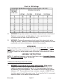
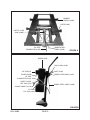
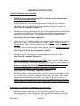
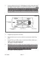
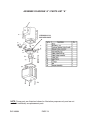
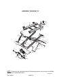
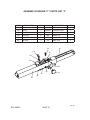
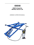
MID-HIGH CAR LIFT
WITH HYDRAULIC PUMP
6,000 POUND CAPACITY
Model 46604
ASSEMBLY and Operating Instructions
Visit our website at: http://www.harborfreight.com
Read this material before using this product.
Failure to do so can result in serious injury.
Save this manual.
Copyright© 2002 by Harbor Freight Tools®. All rights reserved. No portion of this manual or any artwork
contained herein may be reproduced in any shape or form without the express written consent of Harbor
Freight Tools. Diagrams within this manual may not be drawn proportionally. Due to continuing improvements,
actual product may differ slightly from the product described herein. Tools required for assembly and service
may not be included.
For technical questions or replacement parts, please call 1-800-444-3353.
Revised Manual 10f
SPECIFICATIONS TABLE
Maximum Lift Capacity
6,000 Lb. at 19” Elevation
Electrical Requirements
220 V~/60 Hz/4 A/ 1 HP Motor/Single Phase
Motor RPM: 3,450
Pump Maximum PSI
3,200 PSI
Pump Hydraulic Oil Capacity/Type
1.5 Gallons
ISO VG 32 Hydraulic Oil
(Extreme temperature conditions may require an oil with a
different viscosity – consult a qualified technician.)
Maximum Ram Force
25,000 PSI
Minimum Height
3-7/8” at Top of Plate
7” at Top of Rubber Saddle
Maximum Height
39-3/4” at Top of Rubber Saddle
Maximum Width Between Rubber Saddles
53”
Rubber Saddle Dimensions
5-1/8” x 3-1/2”
Ram
1.50” Diameter
Ram Cylinder
2.55” Diameter
Ram Travel
13.5”
Plate Travel
33.5”
Overall Dimensions
79” L x 39-1/2” W x 39-3/4” H (Up)
85-1/2” L x 39-1/2” W x 7” H (Down)
Weight
752 Pounds
SAVE THIS MANUAL
You will need this manual for the safety warnings and precautions, assembly,
operating, inspection, maintenance and cleaning procedures, parts list and assembly
diagram. Keep your invoice with this manual. Write the invoice number on the inside
of the front cover. Keep this manual and invoice in a safe and dry place for future
reference.
GENERAL SAFETY WARNINGS AND PRECAUTIONS
1.
KEEP WORK AREA CLEAN AND DRY. Cluttered, damp, or wet work areas
invite injuries.
2.
KEEP CHILDREN AWAY FROM WORK AREA. Do not allow children to handle
this product.
3.
STORE IDLE EQUIPMENT. When not in use, tools and equipment should be
stored in a dry location to inhibit rust. Always lock up tools and equipment, and
keep out of reach of children.
REV 05l, 06h, 07c, 10f
SKU 46604
PAGE 2
4.
DO NOT USE THIS PRODUCT IF UNDER THE INFLUENCE OF ALCOHOL OR
DRUGS. Read warning labels on prescriptions to determine if your judgement or
reflexes are impaired while taking drugs. If there is any doubt, do not attempt to
use this product.
5.
USE EYE AND HAND PROTECTION. Wear ANSI approved safety impact
eyeglasses and heavy-duty work gloves when using this product. ANSI
approved safety impact eyeglasses and heavy-duty work gloves are available
from Harbor Freight Tools.
6.
DRESS SAFELY. Do not wear loose clothing or jewelry, as they can become
caught in moving parts. Wear a protective hair covering to prevent long hair from
becoming caught in moving parts. If wearing a long-sleeve shirt, roll sleeves up
above elbows.
7.
DO NOT OVERREACH. Keep proper footing and balance at all times to prevent
tripping, falling, back injury, etcetera.
8.
INDUSTRIAL APPLICATIONS MUST FOLLOW OSHA REQUIREMENT.
9.
STAY ALERT. Watch what you are doing at all times. Use common sense. Do
not use this product when you are tired of distracted from the job at hand.
10.
CHECK FOR DAMAGED PARTS. Before using this product, carefully check that
it will operate properly and perform its intended function. Check for damaged
parts and any other conditions that may affect the operation of this product.
Replace or repair damaged or worn parts immediately.
11.
REPLACEMENT PARTS AND ACCESSORIES: When servicing, use only
identical replacement parts. Only use accessories intended for use with this
product. Approved accessories are available from Harbor Freight Tools.
12.
MAINTAIN THIS PRODUCT WITH CARE. Keep this product clean and dry for
better and safer performance.
13.
MAINTENANCE: For your safety, service and maintenance should be performed
regularly by a qualified technician.
14.
USE THE RIGHT PRODUCT FOR THE RIGHT JOB. There are certain
applications for which this product was designed. Do not use small equipment,
tools, or attachments to do the work of larger industrial equipment, tools, or
attachments. Do not use this product for a purpose for which it was not intended.
SKU 46604
PAGE 3
15.
WARNING: The warnings, precautions, and instructions discussed in this
manual cannot cover all possible conditions and situations that may occur. The
operator must understand that common sense and caution are factors, which
cannot be built into this product, but must be supplied by the operator.
SPECIFIC PRODUCT WARNINGS AND PRECAUTIONS
1.
DO NOT EXCEED THE MAXIMUM LIFT CAPACITY (6,000 POUNDS AT 19”
ELEVATION) FOR THE CAR LIFT. Overloading the Car Lift could cause
personal injury and/or property damage. Caution: Be aware of dynamic loading!
If a weight falls onto the Car Lift, it may create for a brief instant an excess load,
which may result in damage to vehicle, Car Lift and/or personal injury.
2.
OPERATION (RAISING OR LOWERING) OF THE CAR LIFT CAN BE
IMMEDIATELY STOPPED AT ANY TIME BY RELEASING PRESSURE ON THE
POWER SWITCH LOCATED ON THE MOTOR (part #1A).
(See Figure B, and Assy. Diagram A.)
3.
DO NOT USE THE CAR LIFT ON ANY ASPHALT SURFACE. Make sure this
equipment is used on a dry, oil/grease free, flat, level, CONCRETE surface
capable of supporting the weight of the Car Lift, the vehicle being lifted, and
any additional tools and equipment. The concrete floor should have a minimum
thickness of 5”. The concrete must have a minimum strength of 4,000 PSI, and
should be aged at least 30 days prior to use. Do not use the Car Lift on concrete
expansion seams or on cracked, defective concrete.
4.
ALWAYS EXAMINE THE CAR LIFT FOR STRUCTURAL CRACKS, BENDS,
DAMAGE TO THE HYDRAULIC HOSES AND ELECTRICAL WIRING, AND ANY
OTHER CONDITION THAT MAY AFFECT THE SAFE OPERATION OF THE
LIFT. Do not use the Car Lift even if minor damage appears.
5.
MAKE SURE THE OIL TANK (part #12A) IS COMPLETELY FILLED WITH A
PREMIUM QUALITY HYDRAULIC OIL PRIOR TO OPERATING THE CAR LIFT.
(See Figure B, Assy. Diagram A, and the “INSPECTION, MAINTENANCE,
AND CLEANING” section.) Note: The hydraulic tank oil capacity is 1.5
gallons.
6.
MAINTAIN A SAFE WORKING ENVIRONMENT. Keep the work area well lit.
Make sure there is adequate surrounding workspace. Always keep the work area
free of obstructions, grease, oil, trash, and other debris. Do not use the Car Lift
in areas near flammable chemicals, dusts, and vapors.
SKU 46604
PAGE 4
REV 04c, 05b, 10f
7.
8.
PRIOR TO BEGINNING A JOB, MAKE SURE THE SAFETY LOCK ASSEMBLY
(part #36B) AND ITS SAFETY CATCHES ARE IN THE PROPER POSITION.
NEVER work underneath a vehicle without using additional safety support
devices (i.e., jack stands) to support the vehicle.
(See Figure A, and Assy. Diagram B.)
ALWAYS KEEP HANDS, FINGERS, AND FEET AWAY FROM THE MOVING
PARTS OF THE CAR LIFT WHEN APPLYING OR RELEASING A LOAD.
Remain clear of the Car Lift when raising or lowering a vehicle.
9.
USE EXTREME CAUTION WHEN APPLYING OR RELEASING A LOAD. Never
allow the load to suddenly release. Slowly and carefully apply and release the
load.
10.
NEVER LEAVE THE CAR LIFT UNATTENDED WHEN THE LIFT IS UNDER
A LOAD. Whenever the Car Lift is under a load there is a very large amount
of force that has been stored in the Outside/Inside Scissors (parts #24B, #25B)
which must be controlled until the load is relaxed. (See Assy. Diagram B.)
11.
BEFORE DRIVING A VEHICLE ONTO THE CAR LIFT, MAKE SURE THE LIFT
IS FULLY LOWERED. Before driving a vehicle onto the Car Lift, position the
Plates (part #42B) and Rubber Saddles (part #39B) inward. Do not hit or run
over the Plates and Rubber Saddles, as this could damage the vehicle. Make
sure the Car Lift is fully lowered before driving the vehicle off.
(See Figure A, and Assy. Diagram B.)
12.
SHOULD ANY WEIGHT COMPONENT BE REMOVED FROM, OR ADDED TO
THE VEHICLE, USE A JACK STAND (not provided) TO SUPPORT THE OVER
BALANCED END DURING THE MAINTENANCE PROCEDURE. Do not
operate the Car Lift if the vehicle load tilts or binds during the up or down
movement. Always position the vehicle with the center of gravity midway
between the Rubber Saddles (part #39B). Avoid excessive rocking of the vehicle
while it is in the raised position. (See Figure A, and Assy. Diagram B.)
13.
MAKE SURE TO READ AND UNDERSTAND ALL INSTRUCTIONS AND
SAFETY PRECAUTIONS AS OUTLINED IN THE MANUFACTURER’S
MANUAL FOR THE VEHICLE YOU ARE LIFTING. All four Rubber Saddles (part
#39B) of the Car Lift must be used when lifting a vehicle. Always use the vehicle
manufacturer’s recommended lifting points.
(See Figure A, and Assy. Diagram B.)
14.
NEVER LIFT A VEHICLE WITH ANYONE INSIDE IT. Do not allow others in the
lift area while operating the Car Lift. Do not allow anyone to ride on the Car Lift
while it is being raised or lowered.
SKU 46604
PAGE 5
REV 05b
15.
WHEN LIFTING A VEHICLE, RAISE THE RUBBER SADDLES (part #39B)
SLOWLY UNTIL THE RUBBER SADDLES SECURELY CONTACT THE
VEHICLE MANUFACTURER’S RECOMMENDED LIFTING POINTS. Then, lift
the vehicle to the desired working height. CAUTION: Always lift the vehicle high
enough for the Safety Lock Assembly (part #36B) to operate properly.
(See Figure A, and Assy. Diagram B.)
16.
DO NOT USE THE CAR LIFT AS A PERMANENT STAND FOR A VEHICLE.
Use the Car Lift only while making repairs. Then, immediately remove the
vehicle from the Lift.
17.
BEFORE LOWERING THE CAR LIFT, MAKE SURE TOOL TRAYS, STANDS,
AND ALL OTHER TOOLS AND EQUIPMENT ARE REMOVED FROM UNDER
THE VEHICLE.
18.
MAKE SURE TO SQUEEZE AND HOLD THE BRAKE LEVER (part #13B) IN
BEFORE ATTEMPTING TO LOWER THE VEHICLE. Do not release pressure on
the Brake Lever until the Car Lift is completely lowered.
(See Figure B, and Assy. Diagram B.)
19.
BEFORE REMOVING THE VEHICLE FROM THE CAR LIFT, MAKE SURE THE
PLATES (part #42B) AND RUBBER SADDLES (part #39B) ARE MOVED IN
TO PROVIDE AN UNOBSTRUCTED EXIT.
(See Figure A, and Assy. Diagram B.)
20.
THERE IS A WARNING LABEL ATTACHED TO THE CAR LIFT. READ AND
FULLY UNDERSTAND THE CONTENTS OF THE WARNING LABEL. DO NOT
REMOVE THE WARNING LABEL FROM THE CAR LIFT.
21.
GROUND THIS PRODUCT. This product requires the use of a UL approved, 220
Volt, grounded, 3-prong Electrical Power Plug (not provided). It is recommended
that only a qualified electrician install the Power Plug. Never remove the
grounding prong or modify the Power Plug in any way. Do not use adapter plugs
with this product. To comply with the National Electric Code, and to provide
additional protection from the risk of electrical shock, this product should only
be connected to a 220 Volt, 3-hole electrical outlet that is protected by a Ground
Fault Circuit Interrupter (GFCI). (See Figure B.)
22.
IF AN EXTENSION CORD (not provided) IS USED, MAKE SURE TO USE
ONLY UL APPROVED CORDS HAVING THE CORRECT GAUGE AND
LENGTH. (See Chart, next page.)
23.
Not to be used for aircraft purposes.
SKU 46604
PAGE 6
REV 04c, 05b
Chart for 220 Voltage
24.
25.
WARNING: This product contains or produces a chemical known to the State of
California to cause cancer and birth defects (or other reproductive harm).
(California Health & Safety Code 25249.5 et seq.)
WARNING: People with pacemakers should consult their physician(s) before
using this product. Operation of electrical equipment in close proximity to a heart
pacemaker could cause interference or failure of the pacemaker.
UNPACKING
When unpacking, check to make sure all the parts shown on Parts List A and Parts
List B (pages 14, and 15) are included. If any parts are missing or broken, please
call Harbor Freight Tools at the number shown on the cover of this manual as soon as
possible.
ASSEMBLY INSTRUCTIONS
NOTE: For additional references to the parts listed below, refer to Assembly Diagram
A and Assembly Diagram B (pages 14, and 15).
To Determine The Proper Car Lift Location:
1.
WARNING: Do not use the Car Lift on any asphalt surface. Make sure this
equipment is used on a dry, oil/grease free, flat, level, CONCRETE surface
capable of supporting the weight of the Car Lift, the vehicle being lifted, and
any additional tools and equipment. The concrete floor should have a minimum
thickness of 5”. The concrete must have a minimum strength of 4,000 PSI, and
should be aged at least 30 days prior to use. Do not use the Car Lift on concrete
expansion seams or on cracked, defective concrete.
SKU 46604
PAGE 7
REV 05b
Assembly Instructions (continued)
2.
Make sure to check the desired location for possible obstructions such as a low
ceiling, overhead lines, adequate working area, access ways, exits, etcetera.
3.
Make sure to allow a minimum space of 14 feet in front and behind the Car Lift to
accommodate all vehicles. Certain allowances should be made for special
vehicle requirements or unusual floor plans.
To Attach The Hydraulic Pump To The Car Lift:
1.
Locate the Hydraulic Pump unit (parts #1A through #14A) in an area where it will
be out of the way, is safe from damage and weather, and where it can be easily
reached to operate. (See Figure B, and Assy. Diagram A.)
2.
One end of the hydraulic Oil Pipe Connector (part #17B) has been pre-attached
to the Car Lift by the manufacturer. To attach the remaining end of the hydraulic
Oil Pipe Connector to the Hydraulic Pump, wrap the male threads of the Oil Pipe
Connector with about 4” of pipe thread seal tape (not provided). Then, wrench
tighten the Oil Pipe Connector into the threaded Hydraulic Oil Delivery Port located on the side of the Safety Valve Nut Cap (part #7A).
(See Figures A, B, and Assy. Diagram A.)
3.
One end of the Brake Steel Cable (part #10B) has been pre-attached to the Car
Lift by the manufacturer. The Brake Lever Assembly (part #13B) is located on
the remaining end of the Brake Steel Cable, and must be attached to the arm of
the Dolly (part #15B). To do so, slide the Brake Lever Assembly onto the arm
of the Dolly. Then, secure the Brake Lever Assembly to the arm of the Dolly by
tightening the Bolt (part #14B). (See Figures A, B, and Assy. Diagram B.)
To Fill The Oil Tank With Hydraulic Oil:
1.
The Hydraulic Oil Tank (part #12A) has a holding capacity of 1.5 gallons of
hydraulic oil. To fill the Oil Tank, squeeze and hold in the Brake Lever (part #13B)
to release any load on the Car Lift. Remove the Oil Fill Cap on the Oil Tank. Add
a premium quality hydraulic oil until the level of the oil is even with the Oil Fill
Hole. Then, replace the Oil Fill Cap. (See Figure B, and Assy. Diagram A.)
REV 10f
SKU 46604
PAGE 8
RUBBER
SADDLE (#39B)
PLATE (#42B)
SAFETY LOCK
ASSY. (#36B)
BRAKE STEEL
CABLE (#10B)
OIL PIPE
CONNECTOR (#17B)
FIGURE A
MOTOR (#1A)
DOLLY ARM (#15B)
BOLT (#14B)
“UP” SWITCH
POWER CORD
BRAKE LEVER ASSY. (#13B)
OIL PIPE
CONNECTOR (#17B)
SAFETY VALVE
NUT CAP (#7A)
BRAKE STEEL CABLE (#10B)
“DOWN” HANDLE (#11B)
OIL TANK
FILL CAP (#12A)
FIGURE B
SKU 46604
PAGE 9
OPERATING INSTRUCTIONS
To Check The Safety Lock Assembly:
1.
WARNING: Never operate the Car Lift if the Safety Lock Assembly (part
#36B) is not working properly.
2.
Plug the Power Cord into a properly grounded, 3-hole, 220 Volt, electrical
receptacle, and allow several seconds for the Motor (part #1A) to warm up.
(See Figure B, and Assy. Diagram A.)
3.
Squeeze and release the Brake Lever (part #13B) several times and, while doing
so, observe that the Safety Lock Assembly (part #36B) operates properly in
response to the Brake Lever. Then, release pressure on the Brake Lever.
(See Figures A, B, and Assy. Diagram B.)
4.
Press in on the “Up” Switch and hold, and observe that the Safety Lock Assembly
(part #36B) “clicks” into place as the Car Lift rises. NOTE: There are safety
catches on the Safety Lock Assembly as the Car Lift rises. Once the Safety Lock
Assembly locks into each of these safety catches, you must squeeze and hold in
on the Brake Lever (part #13B) to lower the Car Lift.
(See Figures A, B, and Assy. Diagrams A, and B.)
5.
Once the Car Lift is fully elevated, release pressure on the “Up” Switch.
(See Figure B, and Assy. Diagram A.)
6.
Without squeezing the Brake Lever (part #13B), press in on the “Down” Handle
(part #11B) and hold. Observe that the Car Lift will not lower, as the Safety Lock
Assembly (part #36B) is engaged. CAUTION: If the Safety Lock Assembly
does not engage, fully lower the Car Lift and have a qualified service
technician immediately repair the Safety Lock Assembly.
(See Figures A, B, and Assy. Diagrams A, and B.)
7.
Should the Safety Lock Assembly (part #36B) not operate as described in Step
#7, raise the Car Lift slightly to take pressure off the safety catch. Then, while
squeezing the Brake Lever (part #13B), lower the Car Lift fully to the floor.
NOTE: When working properly, you must BOTH squeeze in and hold the Brake
Lever and press in and hold the “Down” Handle (part #11B) to lower the Car Lift.
To Position, Lift, and Lower The Vehicle On The Car Lift:
1.
Before driving the vehicle onto the Car Lift, make sure that the Lift is fully
lowered, and position the Plates (part #42B) and Rubber Saddles (part #39B)
inward. (See Figure A, and Assy. Diagram B.)
SKU 46604
PAGE 10
2.
Drive the vehicle over the Car Lift, while keeping the vehicle parallel with the Lift,
and aligning the center of gravity of the vehicle with the center of the Lift. NOTE:
The “Center of Gravity” (COG) of the vehicle is the “balance point” at which there
is equal weight in front of and behind the COG, and equal weight on both sides
of the COG. The COG is not necessarily the dimensional center of the vehicle,
but is often slightly toward the engine from the dimensional center of the vehicle.
(See Figure C.)
FIGURE C
Drive-on Direction
of Vehicle
Dimensional Center
of Vehicle
Center of Gravity
Vehicle Engine
3.
Engage the parking brake of the vehicle.
4.
Read the vehicle owner’s manual to identify the recommended vehicle lifting
points.
5.
Move the Plates (part #42B) outward, and position the Rubber Saddles (part
#39B) to contact the vehicle lifting points.
(See Figure A, and Assy. Diagram B.)
6.
WARNING: Do not lift the vehicle if you cannot establish secure and level
lifting points. Do not use substandard shims or other devices in place of
approved and recommended Rubber Saddle (part #39B) adapters. Never
use the Car Lift without the Rubber Saddles in place on each Plate (part
#42B), and in contact with the lifting points of the vehicle.
(See Figure A, and Assy. Diagram B.)
SKU 46604
PAGE 11
7.
Once the Rubber Saddles (part #39B) have been positioned under the vehicle
lifting points, operate the “Up” Switch to lift the vehicle slightly, and test to make
sure the vehicle is well balanced and the contact between the Rubber Saddles
and vehicle lifting points are secure. Then, proceed to lift the vehicle to the
desired height. (See Figures A, B, and Assy. Diagrams A, and B.)
8.
NOTE: When the vehicle has been lifted to the desired height, and the Safety
Lock Assembly (part #36B) has locked in place, make sure to install proper safety
jack stands (not provided) under the vehicle while it is raised as an additional
safety measure. (See Figure A, and Assy. Diagram B.)
9.
Once the maintenance/repair to the vehicle is completed, make sure to remove
all tools and materials from under the vehicle and Car Lift. Also, make sure the
work area is clear and it is safe to lower the vehicle.
10.
To lower the Car Lift, use the “Up” Switch, and raise the vehicle slightly to take
weight off the Safety Lock Assembly (part #36B). Remove safety jack stands.
Then, release pressure on the “Up” Switch. (See Figures A, B, and Assy.
Diagrams A, and B.)
11.
Stand well away from the Car Lift and vehicle. Then squeeze and hold in the
Brake Lever (part #13B) while, at the same time, pushing in and holding the
“Down” Handle (part #11B) to slowly lower the vehicle to the ground. With the
vehicle securely on the ground, lower the Car Lift all the way to the floor.
(See Figure B, and Assy. Diagram A.)
12.
Move the Plates (part #42B) and Rubber Saddles (part #39B) inward, out of the
path of the vehicle. (See Figure A, and Assy. Diagram B.)
13.
Disengage the vehicle parking brake, and drive the vehicle out slowly and
carefully.
INSPECTION, MAINTENANCE, AND CLEANING
1.
CAUTION: Always release a load from the Car Lift and disconnect the Lift from
its electrical power source before performing any inspection, maintenance, or
cleaning.
BEFORE EACH USE, inspect the general condition of the Car Lift. Check for
loose screws, misalignment or binding of moving parts, cracked or broken parts,
damaged hydraulic hoses or electrical wiring, rusted, bent, or frayed Brake Steel
Cable and any other condition that may affect its safe operation. If abnormal
noise or vibration occurs, have the problem corrected before further use.
Do not use damaged equipment.
SKU 46604
PAGE 12
2.
Bleeding the Hydraulic System. If you notice deteriorating performance of the
Pump, it may be a result of too much air in the system.
To bleed the system:
1. Remove cap from the oil tank.
2. Raise and lower the lift through its full range a few times (air will escape).
3. Add hydraulic oil, if necessary to top off the tank, and replace the oil tank cap.
3.
4.
PRIOR TO OPERATING THE CAR LIFT, inspect the hydraulic oil level in the Oil
Tank (part #12A). To do so, squeeze and hold in the Brake Lever (part #13B) to
release any load on the Car Lift. Remove the Oil Fill Cap on the Oil Tank. Add a
premium quality hydraulic oil until the level of the oil is even with the Oil Fill Hole.
Then, replace the Oil Fill Cap. (See Figure B, and Assy. Diagram A.)
5.
PERIODICALLY, use a premium quality, lightweight oil to lubricate all moving
parts. Use a premium quality, heavy weight grease to lubricate the Cylinder Pins
(part #31B), Scissors Pins (part #23B), Wheel Pins (parts #26B, #29B), Cylinder
Assemblies (part #35B), Saddle Holders (part #38B), and Plates (part #42B).
(See Assy. Diagram B.)
6.
With a soft brush, soft cloth, or vacuum, remove all debris from the Car Lift.
7.
When necessary, wipe with a damp cloth, using a mild detergent or mild solvent.
8.
When storing, keep the Car Lift covered with a clean cloth.
PLEASE READ THE FOLLOWING CAREFULLY
THE MANUFACTURER AND/OR DISTRIBUTOR HAS PROVIDED THE PARTS LIST AND ASSEMBLY
DIAGRAM IN THIS MANUAL AS A REFERENCE TOOL ONLY. NEITHER THE MANUFACTURER OR
DISTRIBUTOR MAKES ANY REPRESENTATION OR WARRANTY OF ANY KIND TO THE BUYER THAT
HE OR SHE IS QUALIFIED TO MAKE ANY REPAIRS TO THE PRODUCT, OR THAT HE OR SHE IS
QUALIFIED TO REPLACE ANY PARTS OF THE PRODUCT. IN FACT, THE MANUFACTURER AND/OR
DISTRIBUTOR EXPRESSLY STATES THAT ALL REPAIRS AND PARTS REPLACEMENTS SHOULD
BE UNDERTAKEN BY CERTIFIED AND LICENSED TECHNICIANS, AND NOT BY THE BUYER. THE
BUYER ASSUMES ALL RISK AND LIABILITY ARISING OUT OF HIS OR HER REPAIRS TO THE
ORIGINAL PRODUCT OR REPLACEMENT PARTS THERETO, OR ARISING OUT OF HIS OR HER
INSTALLATION OF REPLACEMENT PARTS THERETO.
SKU 46604
PAGE 13
REV 05b
ASSEMBLY DIAGRAM “A” / PARTS LIST “A”
HYDRAULIC OIL
DELIVERY PORT
NOTE; Some parts are listed and shown for illustration purposes only, and are not
available individually as replacement parts.
SKU 46604
PAGE 14
PARTS LIST “B”
PART
DESCRIPTION
QTY
PART
DESCRIPTION
QTY
1B
Table
1
24B
Outer Scissor
1
2B
Retaining Ring (18)
6
25B
Inner Scissor
1
3B
Locking Nut (M20)
1
26B
Wheel Pin
2
4B
Oil Pipe Connector (2)
3
27B
Big Wheel
2
5B
Branch Inlet Pipe
2
28B
Small Wheel
2
6B
Oil Pipe Connector (2)
2
29B
Wheel Pin
2
7B
Oil Supply Fitting
1
30B
Connecting Pin
2
8B
Nut (M8)
4
31B
Cylinder Pin
2
9B
Washer (8)
4
32B
Safety Lock Pin
1
10B
Brake Steel Cable
1
35B
Cylinder Assy. (L/R)
2
11B
“Down” Handle
1
36B
Safety Locking Assy
1
12B
Hex Screw (M8)
4
37B
Retaining Ring (24)
2
13B
Brake Lever Assy
1
38B
Saddle Holder
4
14B
Bolt (M8)
4
39B
Rubber Saddle
4
15B
Dolly
1
40B
Locking Nut
4
16B
Rubber Cap
3
41B
Washer (20)
4
17B
Oil Pipe Connector (1)
1
42B
Plate
4
18B
General Inlet Pipe
1
43B
Bolt (M8x20)
4
19B
Check Valve
2
44B
Ring (15)
2
20B
Safety Lock Pin
1
45B
Wheel
2
21B
Retaining Ring (20)
6
46B
Nut
2
23B
Scissor Pin
2
ASSEMBLY DIAGRAM “B”
42b
39b
38b
1b
43b
41b
40b
3b
32b
29b
36b
2b
30b
28b
2b
25b
21b
24b
21b
26b
44b
35b(l)
21b
4b
31b
5b
7b
37b
23b
35b(r)
11b
8b
9b
18b
12b
13b
27b
21b
20b
16b
2b
6b
19b
17b
10b
14b
45b
15b
46b
NOTE: Some parts are listed and shown for illustration purposes only, and are not available
individually as replacement parts.
REV 06h, 07c
SKU 46604
PAGE 15
ASSEMBLY DIAGRAM “C” / PARTS LIST “C”
PART
DESCRIPTION
QTY
PART
1C
Pin
1
7C
2C
Spring
1
8C310B
3C
Lock Block
1
4C
Lock Pole
5C
6C
DESCRIPTION
QTY
Bolt (M8)
1
Brake Wire Cable
1
9C
Lock Sheath
1
3
10C
Washer (12)
1
Lock Wheel
1
11C
Bolt (M12)
1
Nut (M8)
1
12C
Check Valve
1
2C
11C
4C
1C
10C
12C
3C
6C
7C
9C
5C
8C
REV 07c
SKU 46604
PAGE 16
schEMAtic
SKU 46604
PAGE 17
REV 07c
LIMITED 90 DAY WARRANTY
Harbor Freight Tools Co. makes every effort to assure that its products meet high
quality and durability standards, and warrants to the original purchaser that this product
is free from defects in materials and workmanship for the period of 90 days from the date
of purchase. This warranty does not apply to damage due directly or indirectly, to misuse,
abuse, negligence or accidents, repairs or alterations outside our facilities, criminal activity,
improper installation, normal wear and tear, or to lack of maintenance. We shall in no event
be liable for death, injuries to persons or property, or for incidental, contingent, special
or consequential damages arising from the use of our product. Some states do not allow
the exclusion or limitation of incidental or consequential damages, so the above limitation
of exclusion may not apply to you. This warranty is expressly in lieu of all
other warranties, express or implied, including the warranties of
merchantability and fitness.
To take advantage of this warranty, the product or part must be returned to us with
transportation charges prepaid. Proof of purchase date and an explanation of the complaint
must accompany the merchandise. If our inspection verifies the defect, we will either
repair or replace the product at our election or we may elect to refund the purchase price
if we cannot readily and quickly provide you with a replacement. We will return repaired
products at our expense, but if we determine there is no defect, or that the defect resulted
from causes not within the scope of our warranty, then you must bear the cost of returning
the product.
This warranty gives you specific legal rights and you may also have other rights
which vary from state to state.
3491 Mission Oaks Blvd. • PO Box 6009 • Camarillo, CA 93011 • (800) 444-3353
SKU 46604
PAGE 18
REV 07c