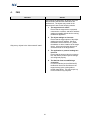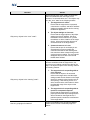
1
Instruction
Manual
October 21, 2014
© 2014 Industrial Control Communications, Inc.
ICC
NetLink
User's Manual
Printed in U.S.A.
©2014 Industrial Control Communications, Inc.
All rights reserved
NOTICE TO USERS
Industrial Control Communications, Inc. reserves the right to make changes and improvements to its
products without providing notice.
Industrial Control Communications, Inc. shall not be liable for technical or editorial omissions or mistakes
in this manual, nor shall it be liable for incidental or consequential damages resulting from the use of
information contained in this manual.
INDUSTRIAL CONTROL COMMUNICATIONS, INC.’S PRODUCTS ARE NOT AUTHORIZED FOR USE
AS CRITICAL COMPONENTS IN LIFE-SUPPORT DEVICES OR SYSTEMS. Life-support devices or
systems are devices or systems intended to sustain life, and whose failure to perform, when properly used
in accordance with instructions for use provided in the labeling and user's manual, can be reasonably
expected to result in significant injury.
No complex software or hardware system is perfect. Bugs may always be present in a system of any size.
In order to prevent danger to life or property, it is the responsibility of the system designer to incorporate
redundant protective mechanisms appropriate to the risk involved.
This user’s manual may not cover all of the variations of interface applications, nor may it provide
information on every possible contingency concerning installation, programming, operation, or
maintenance.
The contents of this user’s manual shall not become a part of or modify any prior agreement, commitment,
or relationship between the customer and Industrial Control Communications, Inc. The sales contract
contains the entire obligation of Industrial Control Communications, Inc. The warranty contained in the
contract between the parties is the sole warranty of Industrial Control Communications, Inc., and any
statements contained herein do not create new warranties or modify the existing warranty.
1
ICC
TABLE OF CONTENTS
1.
Introduction ................................................................................................................................................ 4
2.
Features ...................................................................................................................................................... 5
3.
Using NetLink .............................................................................................................................................. 7
3.1 Object List ........................................................................................................................................................7
3.1.1
Connection Status ....................................................................................................................................8
3.1.1.1
Disconnected.....................................................................................................................................8
3.1.1.2
Connected .........................................................................................................................................8
3.1.1.3
Warning.............................................................................................................................................8
3.1.1.4
Error ..................................................................................................................................................8
3.1.2
Options Menu ...........................................................................................................................................9
3.1.2.1
Import/Export ...................................................................................................................................9
3.1.2.2
Sort By ...............................................................................................................................................9
3.1.2.3
Delete All ...........................................................................................................................................9
3.1.2.4
View Groups ......................................................................................................................................9
3.1.2.5
View Graphs ......................................................................................................................................9
3.1.2.6
Browse Network................................................................................................................................9
3.1.2.7
Settings............................................................................................................................................10
3.1.2.8
Online Help .....................................................................................................................................10
3.1.2.9
About ..............................................................................................................................................10
3.1.3
Creating/Editing an Object (Object Settings) .........................................................................................11
3.1.3.1
Demo Object Settings......................................................................................................................11
3.1.3.2
Modbus/TCP Object Settings ..........................................................................................................12
3.1.3.3
BACnet/IP Object Settings ...............................................................................................................14
3.1.4
Commanding an Object’s Value .............................................................................................................16
3.1.4.1
Entering a New Value ......................................................................................................................16
3.1.4.2
Selecting a New Value .....................................................................................................................17
3.1.4.3
Relinquishing a Value (BACnet only) ...............................................................................................18
3.1.5
Object Options ........................................................................................................................................19
3.1.5.1
Edit ..................................................................................................................................................19
3.1.5.2
Delete ..............................................................................................................................................19
3.2 Groups ...........................................................................................................................................................20
3.2.1
Options Menu .........................................................................................................................................21
3.2.1.1
Add New Group ...............................................................................................................................21
3.2.1.2
Delete All Groups ............................................................................................................................21
3.2.2
Group Options ........................................................................................................................................22
3.2.2.1
Command All Objects ......................................................................................................................22
3.2.2.2
Select Objects ..................................................................................................................................22
3.2.2.3
Edit Group Name.............................................................................................................................22
3.2.2.4
Delete Group ...................................................................................................................................22
3.3 Graphs ...........................................................................................................................................................23
3.3.1
Options Menu .........................................................................................................................................24
3.3.1.1
Add New Graph ...............................................................................................................................24
3.3.1.2
Graph Zoom Method ......................................................................................................................24
3.3.1.3
Reset All Zooming............................................................................................................................24
3.3.1.4
Reset All Sizes ..................................................................................................................................24
3.3.1.5
Delete All Graphs ............................................................................................................................24
3.3.2
Creating/Editing a Graph (Graph Settings) ............................................................................................25
3.3.2.1
Title .................................................................................................................................................25
3.3.2.2
Type.................................................................................................................................................25
2
ICC
3.3.2.3
Size ..................................................................................................................................................25
3.3.2.4
Min Value ........................................................................................................................................25
3.3.2.5
Max Value .......................................................................................................................................25
3.3.2.6
Sample Rate (Secs) ..........................................................................................................................25
3.3.3
Graph Options ........................................................................................................................................26
3.3.3.1
Select Graph Data ...........................................................................................................................26
3.3.3.2
Edit Graph .......................................................................................................................................26
3.3.3.3
Delete Graph ...................................................................................................................................26
3.4 Object Discovery............................................................................................................................................27
3.4.1
Device Scan Range .................................................................................................................................27
3.4.1.1
Start Device .....................................................................................................................................27
3.4.1.2
End Device .......................................................................................................................................27
3.4.1.3
Start IP .............................................................................................................................................27
3.4.1.4
End IP ..............................................................................................................................................27
3.4.2
Additional Discovery Settings .................................................................................................................27
3.5 Settings ..........................................................................................................................................................28
3.5.1
Protocol ..................................................................................................................................................28
3.5.2
Protocol Settings ....................................................................................................................................28
3.5.2.1
Demo Mode Settings.......................................................................................................................28
3.5.2.2
Modbus/TCP Settings ......................................................................................................................28
3.5.2.3
BACnet/IP Settings ..........................................................................................................................28
3.5.3
Demo Mode Settings ..............................................................................................................................29
3.5.3.1
Scan Rate .........................................................................................................................................29
3.5.4
Modbus/TCP Settings .............................................................................................................................30
3.5.4.1
Scan Rate .........................................................................................................................................30
3.5.4.2
Timeout ...........................................................................................................................................30
3.5.4.3
Port..................................................................................................................................................30
3.5.4.4
Modbus Over TCP............................................................................................................................30
3.5.4.5
Device Discovery Settings................................................................................................................30
3.5.4.6
Holding Register Discovery Settings ................................................................................................31
3.5.4.7
Input Register Discovery Settings ....................................................................................................32
3.5.4.8
Coil Discovery Settings ....................................................................................................................33
3.5.4.9
Discrete Input Discovery Settings....................................................................................................34
3.5.5
BACnet/IP Settings .................................................................................................................................35
3.5.5.1
Scan Rate .........................................................................................................................................35
3.5.5.2
Timeout ...........................................................................................................................................35
3.5.5.3
Port..................................................................................................................................................35
3.5.5.4
Device Object Configuration ...........................................................................................................35
3.5.5.5
BBMD Configuration .......................................................................................................................35
3.5.5.6
Foreign Device (FD) Configuration ..................................................................................................36
3.5.5.7
Broadcast Distribution Table ...........................................................................................................37
3.5.5.8
Foreign Device Registration Table ...................................................................................................39
4.
FAQ ........................................................................................................................................................... 41
3
ICC
1.
Introduction
NetLink is an Android-based communications client that enables data access to a variety of remote server
devices. Using NetLink, technicians and maintenance personnel have the ability to conveniently interact
with building automation systems and factory controls from on-site or around the globe with any Android
smartphone or tablet.
Individual network drivers are installed as plugins to the NetLink Application, thereby allowing expandable
access to a variety of popular networking protocols, such as Modbus and BACnet. This commonality
provides a uniform interface, configuration and application experience, thereby reducing the user's
learning curve and commissioning time.
NetLink is a free download and comes packaged with a demo mode plugin that generates random data
values for evaluation purposes.
4
ICC
2.
Features
NetLink Features
• Multiprotocol support via independently-installed plugins
• Select desired protocol and configure data access definitions
• Monitor and command data values
• Add data access definitions from discovered objects on the network
• Import and Export configuration settings
• Supports three types of user-configurable graphs for data visualization:
o Bar graph
o Line graph
o Step graph
• Supports organizing data items into commandable groups
• Allows a variety of data item sorting options
• Supports configuration of an unlimited number of data items
• Both portrait and landscape view modes are fully supported
• Compatible with phones and tablets running Android 2.2 and higher
• Supports data value scaling, units text, and decimal or hexadecimal values
• Real-time connection status feedback for all objects
• Free download, includes demo mode plugin
Modbus/TCP Plugin Features
• Access Modbus server devices over local networks or the internet
• Supports access to holding register, input register, coil and discrete input elements
• Configurable destination port, scan rate and timeout
• Supports Modbus RTU over TCP
• Discover Modbus devices on the local network or over the internet
• Configurable device and object discovery ranges
• Select between different write functions for registers and coils
• Supports data value scaling, units text, signed and unsigned data types, and decimal or
hexadecimal values
• 32-bit registers are fully supported, including floating point values
• The communication to each target device is handled independently, resulting in increased
performance
BACnet/IP Plugin Features
• Access BACnet server devices over local networks or the internet
• Supports access to analog input, analog output, analog value, binary input, binary output, binary
value, multi-state input, multi-state output, and multi-state value object types
• Configurable destination port, scan rate and timeout
• Write priority can be selected for each object
• Discover BACnet devices on the local network or over the internet
• Supports data value scaling, units text, and decimal or hexadecimal values
• Supports BBMD and foreign device registration functionality for accessing BACnet devices across
subnet boundaries and throughout the internet
• Configurable device name and device instance
5
ICC
OEM Customer Features
rd
• 3 -party project-specific licensing options available
• Ability to embed any of the NetLink Application and plugin screens as components of other
Android applications
• Access plugin services independent of the NetLink application via standard Android APIs
6
ICC
3.
Using NetLink
3.1 Object List
The object list displays all created objects and their
values for the selected protocol. The object values are
updated in real time. Each object is displayed with a
connection status icon and corresponding color which
indicates the current connection status of the object
(refer to section 3.1.1 for more details). To create a new
object, tap the button at the top of the list (refer to section
3.1.3). To access the options menu, tap the menu button
on your device (refer to section 3.1.1). To view individual
object options, tap and hold on an item in the list (refer to
section 3.1.5).
7
ICC
3.1.1 Connection Status
The connection status of an object is reflected by the icon shown and the coloring of the text. The different
connection states are detailed below.
3.1.1.1 Disconnected
This icon is displayed with the text colored white
to indicate that a connection is not established for the
object. An object will be in this state initially before
establishing a connection. An object will also be in this
state if a request times out, or the application cannot
establish a connection with the target device.
3.1.1.2 Connected
This icon is displayed with the text colored green
to indicate that a connection is established for an object.
An object will always be in this state during error-free
communication. While an object is connected, its value
can be regarded as valid and up-to-date.
3.1.1.3 Warning
This icon is displayed with the text colored yellow
to indicate that a connection is established for an object,
but the value cannot be read due to an error. An object
will be in this state if it receives an exception or error
response from the target device. For example, an object
will be in this state if the object does not exist on the
target device.
3.1.1.4 Error
This icon is displayed with the text colored red to
indicate that a connection error has occurred for an
object. A connection error occurs if a connection cannot
be established with the target device, or an internal
connection error has occurred such as the port being in
use.
8
ICC
3.1.2 Options Menu
To access the options menu, tap the menu button on your device. Depending on the device, some menu
options may reside under a “More” selection in the menu.
3.1.2.1 Import/Export
This allows a user to either import or export an entire
configuration, which includes all objects, graphs, and
settings for all available protocols, from or to a file
located on the SD card. When exporting a file, the user
may enter a name to save the file as, or simply use the
default name. The location on the SD card where the
files are stored is the directory entitled “NetLink”. Note
that when a configuration is imported, this clears all the
currently-configured objects, graphs, and settings for all
protocols.
3.1.2.2 Sort By
This allows the user to sort the object list. The available
options are created, connection status, description, type,
value, and units. To toggle between ascending and
descending ordering simply select the currently selected
sorting option again.
3.1.2.3 Delete All
This deletes all the objects in the object list. Use caution
when executing this, as this operation cannot be undone.
3.1.2.4 View Groups
Select this to view the group screen. The group screen
displays all configured groups for the selected protocol.
For more information on the group screen, refer to
section 3.2.
3.1.2.5 View Graphs
Select this to view the graph screen. The graph screen
displays all configured graphs for the selected protocol.
For more information on the graph screen, refer to
section 3.3.
3.1.2.6 Browse Network
Select this to view the object discovery screen. The
object discovery screen allows a user to browse for
objects on the currently connected network. Discovered
objects can then be added to the object list.
9
ICC
3.1.2.7 Settings
Select this to view the settings for the application and
installed protocol plugins.
3.1.2.8 Online Help
Select this to go to the online support page where this
manual may be downloaded.
3.1.2.9 About
Select this to view information about the application such
as the application version.
10
ICC
3.1.3 Creating/Editing an Object (Object Settings)
The object settings screen allows a user to edit an existing object or create a new one. The options
available depend on the selected protocol.
3.1.3.1 Demo Object Settings
3.1.3.1.1 Description
This is the name displayed in the object list.
3.1.3.1.2 Type
Select a type for the object. The available types are
described below:
•
Analog Input
This object simulates an integer value from 0 to
100 that is read-only.
•
Analog Output
This object simulates an integer value from 0 to
100 that is both readable and writeable.
•
Digital Input
This object simulates a binary, on-off, value from
0 to 1 that is read-only.
•
Digital Output
This object simulates a binary, on-off, value from
0 to 1 that is both readable and writeable.
3.1.3.1.3 Inst Num
This is the instance number for the object. This is used
to reference the specific simulated object to read and (if
the object type allows) write values.
3.1.3.1.4 Multiplier and Offset
These fields are used for scaling the value of the object.
The scaling equation used is y = mx + b, where y is the
value displayed in the object list, m is the multiplier, x is
the network value of the object, and b is the offset.
3.1.3.1.5 Units
This is the units displayed beside the value in the object
list.
3.1.3.1.6 Radix
Select whether this object’s value should be displayed
and modified in decimal or hexadecimal.
11
ICC
3.1.3.2 Modbus/TCP Object Settings
3.1.3.2.1 Description
This is the name displayed in the object list.
3.1.3.2.2 IP Address
This is the IP Address to target for the Modbus/TCP
server. Enter an IP Address or hostname in this field.
3.1.3.2.3 Unit ID
The implementation of the unit ID is defined by the
Modbus/TCP server. Typically, it is used as the device ID
field for addressing multiple devices with the same IP
address.
3.1.3.2.4 Type
Select a type for the object. The available types are
described below:
•
Holding Register
This object is a Modbus holding register which
has an integer value from 0 to 65535 and is both
readable and writeable.
•
Input Register
This object is a Modbus input register which has
an integer value from 0 to 65535 and is readonly.
•
Coil
This object is a Modbus coil which has a binary
(on/off) value of 0 or 1 that is both readable and
writeable.
•
Discrete Input
This object is a Modbus discrete input which has
a binary (on/off) value of 0 or 1 that is read-only.
3.1.3.2.5 Reg Num / Coil Num / Input Num
This is the register number for holding or input registers,
the coil number for coils, or the input number for discrete
inputs. This is used to target the specific object to read
and (if the object type allows) write values.
3.1.3.2.6 Multiplier and Offset
See section 3.1.3.1.4.
3.1.3.2.7 Units
See section 3.1.3.1.5.
12
ICC
3.1.3.2.8 Radix
See section 3.1.3.1.6.
3.1.3.2.9 Write Func
Select the write function code to use. Note that this
option is only available for Holding Register and Coil
Status types.
3.1.3.2.10 Data Type
Select a data type for the object. This selection will affect
how the value for this object is interpreted when
displayed in the object list and when written to the target
device. Note that the data type selection is only available
for Holding Register and Input Register types. The
available types are listed below:
•
16-bit Unsigned
•
16-bit Signed
•
32-bit Unsigned
•
32-bit Signed
•
32-bit Floating Point
3.1.3.2.11 32-bit Options
The 32-bit options allows advanced configuration of 32bit data types.
3.1.3.2.11.1 Word Swap
Check this to swap the 16-bit words which comprise the
32-bit register.
3.1.3.2.11.2 Word Addressing
Check this if a 32-bit register is composed of two
Modbus register addresses (two 16-bit Modbus registers)
on the target device.
13
ICC
3.1.3.3 BACnet/IP Object Settings
3.1.3.3.1 Description
This is the name displayed in the object list.
3.1.3.3.2 Dest Dev Inst
This is the destination device instance to target for this
object. Each device on the BACnet/IP network will have
a unique device instance associated with it.
3.1.3.3.3 Type
Select a type for the object. The available types are
described below:
•
Analog Input
This object represents a physical analog real
(32-bit floating point) value that is read-only.
•
Analog Output
This object represents a physical analog real
(32-bit floating point) value that is both readable
and writeable.
•
Analog Value
This object represents a virtual analog real (32bit floating point) value that is both readable and
writeable.
•
Binary Input
This object represents a physical digital (on/off)
value of 0 or 1 that is read-only.
•
Binary Output
This object represents a physical digital (on/off)
value of 0 or 1 that is both readable and
writeable.
•
Binary Value
This object represents a virtual digital (on/off)
value of 0 or 1 that is both readable and
writeable.
•
Multi-state Input
This object represents a physical state (32-bit
unsigned integer) that is read-only.
•
Multi-state Output
This object represents a physical state (32-bit
unsigned integer) that is both readable and
writeable.
•
Multi-state Value
This object represents a virtual state (32-bit
unsigned integer) that is both readable and
writeable.
14
ICC
3.1.3.3.4 Inst Num
This is the instance number for the object. This is used
to reference the specific object on the target device to
read and (if the object type allows) write values.
3.1.3.3.5 Multiplier and Offset
See section 3.1.3.1.4.
3.1.3.3.6 Units
See section 3.1.3.1.5.
3.1.3.3.7 Radix
See section 3.1.3.1.6.
3.1.3.3.8 Write Priority
Select the priority to assign to writes for this object.
BACnet write priorities may have a value from 1 to 16,
where 16 is the lowest priority. Selecting “None” will use
a write priority of 16, but will not allow the ability to
relinquish values. Note that the write priority setting is
only available for writeable objects (Output and Value
objects).
15
ICC
3.1.4 Commanding an Object’s Value
Writeable objects can be command from the object list by tapping on the list item.
3.1.4.1 Entering a New Value
For object types that have an adjustment range larger
than 0 to 1, any decimal or hexadecimal value
(depending on the radix selected for the object) within
the allowable range of the object may be entered into the
edit box. Note that because some protocols use integer
values instead of real (floating point) values, digits after
the decimal place may be dropped.
16
ICC
3.1.4.2 Selecting a New Value
For binary (on/off) object types that have a range of 0 to
1, either a value of Off (corresponding to 0) or On may
be selected.
17
ICC
3.1.4.3 Relinquishing a Value (BACnet only)
For BACnet object types configured with a write priority
other than “None”, the value written at the configured
priority may be relinquished by checking the “Relinquish
Value” check box. Relinquishing a value writes a NULL
to the object’s value at the assigned priority. This option
is available regardless of whether a new value is being
entered or selected.
18
ICC
3.1.5 Object Options
Tap and hold on an item in the object list to access the object options menu.
3.1.5.1 Edit
Select this option to edit the object settings. Refer to
section 3.1.3 for details.
3.1.5.2 Delete
Select this option to delete the selected object. Note that
this action cannot be undone.
19
ICC
3.2 Groups
The group screen allows selected objects from the
Object List to be grouped under a common heading. This
can be useful for organizing objects that share common
attributes (floors in a building, for example) as well as
grouping commandable objects to write a value to all
objects simultaneously. To create a new group, tap the
“Add New Group” button in the options menu (refer to
section 3.2.1). To select data items to be members of a
group, tap and hold a group heading to display the group
options (refer to section 3.2.2).
20
ICC
3.2.1 Options Menu
To access the options menu, tap the menu button on your device.
3.2.1.1 Add New Group
Select this to append a new group to the end of the
group screen.
3.2.1.2 Delete All Groups
This deletes all the groups from the group screen. Use
caution when performing this operation as it cannot be
undone.
21
ICC
3.2.2 Group Options
To access the options menu of a particular group, tap and hold on a group heading to bring up the Group
Options menu.
3.2.2.1 Command All Objects
Select this option to simultaneously write a value to all of
the objects in the selected group. Note that this option is
only available for groups composed of writable objects
that have the same scaled range for their values. For
BACnet objects, the “Relinquish Value” option will be
available when entering or selecting a new value if all
objects in the group are configured with a write priority
other than “None”.
3.2.2.2 Select Objects
Select this option to choose which objects are to be
members of the selected group. Note that individual
objects may be members of more than one group if
desired.
3.2.2.3 Edit Group Name
Select this option to edit the name of the group.
3.2.2.4 Delete Group
Select this option to delete the selected group. Note that
this action cannot be undone.
22
ICC
3.3 Graphs
The graph screen displays all created graphs and their
associated data for the selected protocol. The object
values are updated periodically depending on the sample
rate configured (refer to section 3.3.2). To create a new
graph, tap the “Add New Graph” button in the options
menu (refer to section 3.3.1). To configure the data
displayed in the graph, tap and hold a graph to display
the graph options (refer to section 3.3.3).
All graphs can be zoomed in and out using pinch-tozoom, two finger gestures. The graphs can also be
scrolled, or panned, when zoomed. Two different zoom
methods are supported. These methods are described in
section 3.3.1.2.
23
ICC
3.3.1 Options Menu
To access the options menu, tap the menu button on your device.
3.3.1.1 Add New Graph
Select this to append a new graph to the end of the
graphs screen. Refer to section 3.3.2 for details on
creating graphs.
3.3.1.2 Graph Zoom Method
Select the zoom method to use when using pinch-tozoom gestures on graphs. Image Zoom allows you to
zoom in or out on a particular are of the graph, as if you
were scaling an image. Data Zoom allows you to
increase or decrease the range shown on each of the
graph’s axes.
3.3.1.3 Reset All Zooming
This resets all graphs to their default zooms.
3.3.1.4 Reset All Sizes
This resets all graphs to their default sizes.
3.3.1.5 Delete All Graphs
This deletes all the graphs from the graph screen. Use
caution when executing this, as this operation cannot be
undone.
24
ICC
3.3.2 Creating/Editing a Graph (Graph Settings)
The graph settings screen allows a user to edit an existing graph or create a new one.
3.3.2.1 Title
Enter the title to display at the top of the graph.
3.3.2.2 Type
Select a type for the object. Note that the type cannot be
modified when editing graph settings of an existing
graph. The available types are described below:
•
Bar Graph
This graph displays bars which grow and shrink
vertically to indicate the current value of the data
displayed. A new bar is drawn for each data
item selected.
•
Line Graph
This graph displays a moving line with 30 history
samples. A new line is drawn for each data item
selected.
•
Step Graph
This graph displays a block which moves with a
30-sample history as well as grows and shrinks
vertically to indicate the sampled value of the
data displayed.
3.3.2.3 Size
Move this slider to configure the percentage of the
screen this graph will occupy. To reset the size of this
graph to the default size, click on the reset button on the
right of the slider.
3.3.2.4 Min Value
Enter the minimum value to display on the Y axis of the
graph.
3.3.2.5 Max Value
Enter the maximum value to display on the Y axis of the
graph.
3.3.2.6 Sample Rate (Secs)
This is the rate at which data points are drawn on the
graph, in seconds. For line and step graphs, the X axis
will be scaled by this value. For example, a line graph
with a sample rate of 10 seconds will display values from
now until 300 seconds ago, while one with a sample rate
of 2 seconds will display values from now until 60
seconds ago (30 history samples total in each case).
25
ICC
3.3.3 Graph Options
To access the options menu of a particular graph, tap and hold on a graph to bring up the Graph Options
menu.
3.3.3.1 Select Graph Data
Select this option to choose which data items to display
in the selected graph.
3.3.3.2 Edit Graph
Select this option to edit the graph settings. Refer to
section 3.3.2 for details.
3.3.3.3 Delete Graph
Select this option to delete the selected graph. Note that
this action cannot be undone.
26
ICC
3.4 Object Discovery
The object discovery screen enables browsing for
objects on the currently connected network or over the
internet. To search for devices in a specific range, enter
the desired start and end device instance or IP address
limits and click the scan button. Once a device is
discovered, tap on the device entry to discover its
objects. To add objects to the object list, check the
checkbox next to an object, or check the checkbox next
to a device itself to select all objects on that device.
Then click the “Add Objects button” to add the objects to
the Object List (refer to section 3.1).
3.4.1 Device Scan Range
By default, the object discovery will scan for all devices
on the network. To restrict either the start device, end
device, or both, enter limits in these fields. Depending on
the protocol, the start device and end device are
specified by either an instance number or an IP address.
3.4.1.1 Start Device
Enter the lowest device instance to scan for. This field
may be left blank.
3.4.1.2 End Device
Enter the highest device instance to scan for. This field
may be left blank.
3.4.1.3 Start IP
Enter the lowest IP address or hostname to scan for.
This field must contain a valid IP address or hostname.
3.4.1.4 End IP
Enter the highest IP address or hostname to scan for.
This field must contain a valid IP address or hostname.
3.4.2 Additional Discovery Settings
Some protocols (such as Modbus/TCP) may require
additional discovery settings. These settings can be
found in the protocol settings for each plugin. Refer to
section 3.5.4 for details on the discovery settings for the
Modbus/TCP plugin.
27
ICC
3.5 Settings
To access the application’s settings, select Settings from the options menu on the object list screen.
3.5.1 Protocol
Select the desired protocol that the application will use.
This will change the objects displayed in the object list
and the graphs that are displayed. When changing
protocols, no configuration data is lost. For example,
objects and graphs for the Modbus/TCP protocol can be
created, then BACnet/IP may be selected and objects
and graphs for the BACnet/IP protocol can be created.
Switching between these two configurations can then be
accomplished by selecting the corresponding protocol
from this menu.
3.5.2 Protocol Settings
These settings are specific to each individual plugin.
Note that some installed plugins may not require these
settings, and therefore will not appear in this list.
Only the settings for the currently-selected protocol are
enabled: all other available (but not selected) Protocol
Setting selections are greyed out. Refer to section 3.5.1
for information on changing the currently-selected
protocol.
3.5.2.1 Demo Mode Settings
Select this to access the settings for the Demo Mode
plugin included with NetLink. Refer to section 3.5.3 for
details.
3.5.2.2 Modbus/TCP Settings
Select this to access the settings for the Modbus/TCP
plugin. Refer to section 3.5.4 for details.
3.5.2.3 BACnet/IP Settings
Select this to access the settings for the BACnet/IP
plugin. Refer to section 3.5.5 for details.
28
ICC
3.5.3 Demo Mode Settings
3.5.3.1 Scan Rate
Enter the time in milliseconds that the Demo Mode plugin
should delay between generating values for consecutive
objects. The default value is 1000 (1 second).
29
ICC
3.5.4 Modbus/TCP Settings
3.5.4.1 Scan Rate
Enter the time in milliseconds that the Modbus plugin
should delay between network requests. The default
value is 1000 (1 second).
3.5.4.2 Timeout
Enter the time in milliseconds that the Modbus plugin will
wait for a response after sending a network request. The
default value is 10000 (10 seconds).
3.5.4.3 Port
Enter the desired TCP/IP port to use for Modbus/TCP
communications. The default value is 502.
3.5.4.4 Modbus Over TCP
When checked, Modbus communications will use the
Modbus RTU over TCP protocol instead of the standard
Modbus/TCP protocol.
3.5.4.5 Device Discovery Settings
This section specifies the settings used when
discovering devices on a Modbus/TCP network (refer to
section 3.4 for further details regarding device
discovery). Independent settings exist for discovery of
holding registers, input registers, coils and discrete
inputs. This flexibility enhances discovery optimization
by allowing the ability to target only the elements and
ranges that are applicable for the devices on a given
network.
3.5.4.5.1 Start Unit ID
Enter the lowest unit ID to discover on the network. The
default value is 1.
3.5.4.5.2 End Unit ID
Enter the highest unit ID to discover on the network. The
default value is 1.
30
ICC
3.5.4.6 Holding Register Discovery Settings
This section specifies the settings used when
discovering holding register object types on a
Modbus/TCP device.
3.5.4.6.1 Discover Holding Registers
Check this box to enable the discovery of holding
registers. This is enabled by default.
3.5.4.6.2 Start Holding Register
Enter the lowest holding register index to discover on a
device. The default value is 1.
3.5.4.6.3 End Holding Register
Enter the highest holding register index to discover on a
device. The default value is 100.
3.5.4.6.4 Write Function
Select the write function to use for all discovered holding
registers that are added to the object list.
3.5.4.6.5 Type
Select the data type to use for all discovered holding
registers that are added to the object list.
3.5.4.6.6 Word Swap
Check this box to swap the 16-bit words which comprise
a 32-bit register for all discovered holding registers that
are added to the object list. Note that this setting is
available only if a 32-bit data type is selected.
3.5.4.6.7 Word Addressing
Check this box if a 32-bit register is comprised of two 16bit register addresses for all discovered holding registers
that are added to the object list. Note that this setting is
available only if a 32-bit data type is selected.
31
ICC
3.5.4.7 Input Register Discovery Settings
This section specifies the settings used when
discovering input register object types on a Modbus/TCP
device.
3.5.4.7.1 Discover Input Registers
Check this box to enable the discovery of input registers.
This is enabled by default.
3.5.4.7.2 Start Input Register
Enter the lowest input register index to discover on a
device. The default value is 1.
3.5.4.7.3 End Input Register
Enter the highest input register index to discover on a
device. The default value is 100.
3.5.4.7.4 Type
Select the data type to use for all discovered input
registers that are added to the object list.
3.5.4.7.5 Word Swap
Check this box to swap the 16-bit words which comprise
a 32-bit register for all discovered input registers that are
added to the object list. Note that this setting is available
only if a 32-bit data type is selected.
3.5.4.7.6 Word Addressing
Check this box if a 32-bit register is comprised of two 16bit register addresses for all discovered input registers
that are added to the object list. Note that this setting is
available only if a 32-bit data type is selected.
32
ICC
3.5.4.8 Coil Discovery Settings
This section specifies the settings used when
discovering coil object types on a Modbus/TCP device.
3.5.4.8.1 Discover Coils
Check this box to enable the discovery of coils. This is
enabled by default.
3.5.4.8.2 Start Coil
Enter the lowest coil index to discover on a device. The
default value is 1.
3.5.4.8.3 End Coil
Enter the highest coil index to discover on a device. The
default value is 100.
3.5.4.8.4 Write Function
Select the write function to use for all discovered coils
that are added to the object list.
33
ICC
3.5.4.9 Discrete Input Discovery Settings
This section specifies the settings used when
discovering discrete input object types on a Modbus/TCP
device.
3.5.4.9.1 Discover Discrete Inputs
Check this box to enable the discovery of discrete inputs.
This is enabled by default.
3.5.4.9.2 Start Input
Enter the lowest discrete input index to discover on a
device. The default value is 1.
3.5.4.9.3 End Input
Enter the highest discrete input index to discover on a
device. The default value is 100.
34
ICC
3.5.5 BACnet/IP Settings
3.5.5.1 Scan Rate
Enter the time in milliseconds that the BACnet plugin
should delay between network requests. The default
value is 1000 (1 second).
3.5.5.2 Timeout
Enter the time in milliseconds that the BACnet plugin will
wait for a response after sending a network request. The
default value is 10000 (10 seconds).
3.5.5.3 Port
Enter the desired UDP port to use for BACnet/IP
communications. The default value is 47808.
3.5.5.4 Device Object Configuration
3.5.5.4.1 Device Name
Enter the name for the NetLink client device that will
appear on the BACnet/IP network. This name must be
unique on the BACnet/IP network.
3.5.5.4.2 Device Instance
Enter the device instance for the NetLink client device.
This device instance must be unique on the BACnet/IP
network.
3.5.5.5 BBMD Configuration
These settings are used to configure the NetLink client
as a BBMD device (BACnet Broadcast Management
Device).
3.5.5.5.1 Enable BBMD
Check this box to enable BBMD support and enable
configuration of the broadcast distribution table. BBMD
support includes the ability to distribute broadcasts to the
configured broadcast distribution table, as well as to any
foreign devices that have registered with the NetLink
client.
3.5.5.5.2 Broadcast Distribution Table
Select this to view and edit the broadcast distribution
table. To configure the broadcast distribution table, make
sure that “Enable BBMD” is checked. Refer to section
3.5.5.7 for details.
35
ICC
3.5.5.6 Foreign Device (FD) Configuration
These settings are used to allow the NetLink client to
register with remote BBMD devices as a foreign device.
3.5.5.6.1 Enable FD Registration
Check this box to enable registration as a foreign device
with remote BBMD devices, and to enable configuration
of the foreign device registration table.
3.5.5.6.2 Foreign Device Reg Table
Select this to view and edit the foreign device registration
table. To configure this table, ensure that “Enable FD
Registration” is checked.
36
ICC
3.5.5.7 Broadcast Distribution Table
3.5.5.7.1 Overview
The broadcast distribution table displays a list of BBMD
devices that will distribute broadcasts with each other.
The NetLink client will distribute broadcast packets to
each device defined in this table, excluding itself. Note
that this table will always contain a non-editable entry for
the host device’s own IP address. Also note that this
table must be identical to that entered into the other
BBMD devices.
To create a new entry, tap “Add new entry” at the top of
the screen. To edit an existing entry, tap on the entry in
the list. Refer to section 3.5.5.7.2 for details.
37
ICC
3.5.5.7.2 Creating/Editing a Broadcast Distribution Table Entry
3.5.5.7.2.1 IP Address
Enter the IP address of the remote BBMD device.
3.5.5.7.2.2 Port
Enter the port to use when communicating with the
remote BBMD device. The default value is 47808.
3.5.5.7.2.3 Distribution Mask
Enter the mask to use to distribute broadcasts on the
remote BBMD’s network. The default value of
255.255.255.255 will result in a point-to-point connection
between the NetLink client and remote BBMD device.
38
ICC
3.5.5.8 Foreign Device Registration Table
3.5.5.8.1 Overview
The foreign device registration table displays a list of
BBMD devices that the NetLink client will register itself
to. The NetLink client will register as a foreign device to
each device defined in this table.
To create a new entry, tap “Add new entry” at the top of
the screen. To edit an existing entry, tap on the entry in
the list. Refer to section 3.5.5.8.2 for details.
39
ICC
3.5.5.8.2 Creating/Editing a Foreign Device Registration Table Entry
3.5.5.8.2.1 IP Address
Enter the IP address of the remote BBMD device.
3.5.5.8.2.2 Port
Enter the port to use when communicating with the
remote BBMD device. The default value is 47808.
40
ICC
4.
FAQ
Question
Answer
Upon starting the application, all objects are in the
“disconnected” state and their data values are
initialized to 0. The objects may remain in the
“disconnected” state for the following reasons:
1. The target device is offline
Ensure that the target device is powered,
connected to a network, and has IP address
settings compatible with the device running
the NetLink application.
2. The object settings are incorrect
Ensure that the target options of the object
settings (such as IP address, Unit ID or
Destination Device Instance, etc.) match
the address or device instance of the target
device. Also ensure that the object to be
accessed exists on the target device.
Why are my objects in the “disconnected” state?
3. The application or protocol settings are
incorrect
Ensure that the timeout value is not set too
low, and that the protocol-specific settings
are configured properly.
4. The NetLink client is establishing a
connection
For some networks (such as BACnet/IP)
the NetLink client must first discover the
target device(s) prior to being able to
transfer data values. This may require up
to 30 seconds to fully complete.
41
ICC
Question
Answer
Objects are set to the “error” state if a connection
cannot be established with the target device
because of a communication error. The objects may
be in the “error” state for the following reasons:
1. The target device is offline
Ensure that the target device is powered,
connected to a network, and has IP address
settings compatible with the device running
the NetLink application.
2. The object settings are incorrect
Ensure that the target options of the object
settings (such as IP address, Unit ID or
Destination Device Instance, etc.) match
the address or device instance of the target
device. Also ensure that the object to be
accessed exists on the target device.
Why are my objects in the “error” state?
3. A network resource is in use
Ensure that the port is not already in use.
Sometimes this may occur while old
connection threads are still finishing after
new ones have been created during events
such as a screen rotation. The error should
disappear after some time once the old
threads have finished.
Objects are set to the “warning” state if a connection
has been established with the target device, but
there is an error reading or writing the value of the
object. The objects may be in the “warning” state for
the following reasons:
1. The target device is responding with an
error response
Ensure that the object to be accessed
exists on the target device and the object
settings match what is allowed on the target
device (for example, write function code or
write priority). If the warning occurs on a
write, ensure that the value written is within
the allowable range of the object on the
target device.
Why are my objects in the “warning” state?
2. The target device is responding with an
invalid or unexpected response
Ensure that the target device is configured
properly and that the object settings match
what is allowed on the target device. If
problems persist, contact the manufacturer
of the target device.
How do I get plugins for NetLink?
Plugins are available on the Google Play Market.
Please visit the market to download plugins for
NetLink.
42
ICC
Question
Answer
I downloaded a NetLink plugin, now what?
NetLink plugins will be installed on your device, but
will not appear in the application launcher list. To
start using a new plugin, open the NetLink
application, tap the “menu” button on your device,
go to “Settings…Protocol” and select the protocol
supported by the new plugin.
How do I configure the rate that my objects’ values
update?
This can be configured by changing the “Scan Rate”
in the application settings. Refer to section 3.4 for
details.
Can I toggle the sort order of my objects in the
object list between ascending and descending?
Yes. To toggle the sort order from ascending to
descending, tap the device’s menu button, select
“Sort By”, and tap the currently selected option.
I just exported my configuration. Where is the
configuration file saved?
The configuration file will be saved in a folder titled
“NetLink” on the device’s SD card.
I tapped on “View Graphs”, but all I see is a blank
screen. What should I do?
A blank screen will appear if there are no graphs
added to the screen. To add a graph, tap the menu
button on your device and select “Add New Graph”.
Refer to section 3.3.1 for details.
Why isn’t my graph displaying anything?
Make sure that data has been selected for the
graph to use (refer to section 3.3.3.1) and that the
data values of the objects are within the “Min Value”
to “Max Value” range specified in the graph settings
(refer to sections 3.3.2.4 and 3.3.2.5). If the graph is
a line or step graph, make sure that at least two
sample rate time periods have elapsed (refer to
section 3.3.2.6).
Can I request new features or plugins for NetLink?
Yes, please contact us at [email protected] or
by telephone at +1-608-831-1255.
I’m still having problems. What should I do?
Please contact ICC either by email at
[email protected] or by telephone at +1608-831-1255.
43
1600 Aspen Commons, Suite 210
Middleton, WI USA 53562-4720
Tel: [608] 831-1255 Fax: [608] 831-2045
http://www.iccdesigns.com
Printed in U.S.A