1
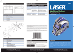
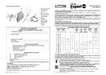
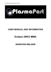
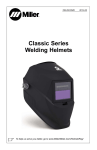
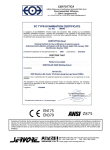
Parts
PROBLEM(S)
POSSIBLE CAUSE(S)
SUGGESTED SOLUTION(S)
Difficult to see through
filter
Front cover lens dirty
Clean or replace front cover lens
Filter cover lens dirty
Clean filter cover lens
Grind Mode Selected
Adjust Shade from 9 to 13
Sensors or Solar Panel
blocked
Make sure sensors or solar panel are
exposed to weld arc without blocking
Set Sensitivity to LOW
Adjust sensitivity to required level
Filter darkens without arc
Set Sensitivity to HIGH
Adjust sensitivity to required level
Filter remains dark
after welding
Set Delay to MAX
Adjust sensitivity to required level
Filter does not darken
when arc is struck
Part
1
2
3
4
5
6
7
8
9
10
6095
Trouble Shooting
Description
Delay Control Knob
Sensitivity Control Knob
Weld/Grind Switch Knob
Self-test Button
Low Voltage Indicator
Shade Number Control Knob
Lithium Batteries
Solar Panel
UV/IR Filter
Arc Sensors
Instructions
Welding Helmet
Auto Darkening
User Manual
Our products are designed to be used correctly and with care for the purpose for which they are intended. No
liability is accepted by the Tool Connection for incorrect use of any of our products, and the Tool Connection
cannot be held responsible for any damage to personnel, property or equipment when using the tools. Incorrect
use will also invalidate the warranty.
If applicable, the applications database and any instructional information provided has been designed to offer
general guidance for a particular tool’s use and while all attention is given to the accuracy of the data no
project should be attempted without referring first to the manufacturer’s technical documentation (workshop or
instruction manual) or the use of a recognised authority such as Autodata.
It is our policy to continually improve our products and thus we reserve the right to alter specifications and
components without prior notice. It is the responsibility of the user to ensure the suitability of the tools and
information prior to their use.
Part
1
2
3
4
5
6
7
8
Description
Helmet Shell
Rubber Gasket
Front Cover Lens
ADF
Cartridge Frame
Headgear Angle Adjusting Knobs
Headgear Height Adjusting Pin
Headgear Diameter Adjusting Knob
www.lasertools.co.uk
Warning!
Guarantee
If this product fails through faulty materials or workmanship, contact our service
department direct on: +44 (0) 1926 818186. Normal wear and tear are excluded
as are consumable items and abuse.
Distributed by The Tool Connection Ltd
Kineton Road, Southam, Warwickshire CV47 0DR
T +44 (0) 1926 815000 F +44 (0) 1926 815888
[email protected] www.toolconnection.co.uk
www.lasertools.co.uk
The Solar-Powered Auto-Darkening Welding Helmet is
suitable for most welding applications. This helmet’s
1/25,000-second switch time automatically darkens
the lens the moment you start welding. No matter what
shade the filter is set to, the UV/IR protection is always
present.
www.lasertools.co.uk
Safety
Operation
ARC Rays can injure eyes
and burn skin
• Before welding, always
inspect helmet and autodarkening filter (ADF) to be
sure they are fitted properly
and in good condition.
• Keep the sensors, solar
cell and filter lens clean. Clean the filter cartridge using a
soapy water solution and soft cloth. Do not use solvents or
abrasive cleaning detergent.
• Do not weld in the overhead position while using this helmet.
• Inspect the filter lens frequently and immediately replace
any scratched, cracked, or pitted filter lens or cover lenses.
• Always wear safety glasses or goggles under the welding
helmet, and protective clothing to protect your skin from
radiation, burns and spatter.
Specifications
Viewing Area
98×62mm
Cartridge Size
133×115mm
UV/IR Protection
UP to shade DIN 16 at all times
Light State/Grind Mode
DIN 4
Dark State
Variable shade, DIN 9 ~ 13
Switch Time
1/25,000S, from Light to Dark
Headgear Adjustment
1.
Adjust the headgear diameter
with the twist knob on the back.
Twist clockwise to tighten and
counterclockwise to loosen.
2.Adjust the height by snapping the
pin into the hole to lock securely in
place.
3.To adjust the viewing angle, loosen
the knob and push the helmet
forward and back to the desired
tilt position. Once the angle is
correct, tighten the knobs until snug. The helmet should still
swing up, but it should not drift downward when in place for
welding.
4.To adjust the distance between the user’s face and ADF,
loosen the outside tension knobs to allow for headgear to
be repositioned to a different location. This should be done
only on right side.
Low - High, by infinitely dial knob
Power Supply
Solar cell and replaceable lithium batteries
Power On/Off
Fully automatic
Arc Sensor
2
TIG AMP Rating
DC≥5, AC≥5
Operating Temperature
-5°C to +55°C
Storing Temperature
-20°C to +70°C
Self-check
ADF Self-test Button and Low Voltage Indicator
Compliance
DIN EN 379:2009-07, DIN EN 175:1997-08
Maintenance
Front Cover Lens Replacement
Self-check
Press the TEST Button anywhere to see if it automatically
switches to dark state and release it to check that the filter
returns to the light state.
Shade Control/Grind Mode
Select the shade 9 to 13 based upon the welding process you
will use by consulting the “Shade Guide Table”. The variable
shade control knob is near inside cover lens for internal
adjustment. The welding helmet can also be used to protect
the face when grinding. Grind mode prevents filter lens from
auto-darkening.
Replace the inside cover lens if it is damaged (cracked,
scratched, pitted or dirty). Remove the old front cover lens
by pressing two Lock Switches at the bottom of the Retaining
Frame and pull the frame and ADF out. Take the old front cover
lens out, and remove any protective film before installing the
new one.
Inside Cover Lens Replacement
Replace the inside cover lens if it is damaged (cracked,
scratched, pitted or dirty). Place your finger or thumb into
the recess as marked above and flex the inside cover lens
upwards until it releases from one edge. Then remove any
protective film before installing the new one.
Dark to Light Time/Delay Control 0.1-1.0S, by infinitely dial knob
Sensitivity Control
Sensitivity Control
The sensitivity can be set to LOW or HIGH by using the infinitely
dial knob on the back of the cartridge. The LOW setting suits
excess ambient light or with another welding machine close
by. The HIGH setting suits low amperage welding and welding
in areas with low light conditions, especially low amperage
argon arc welding. Selections between LOW and HIGH are
suitable for most of indoor and outdoor welding operations.
Delay Control
When welding ceases, the viewing window automatically
changes from dark back to light but with a pre-set delay to
compensate. The delay time can be set to MIN (0.1 sec) or
MAM (1.0 sec), by infinitely dial knob inside the cartridge. The
minimum delay suits spot or short welds. The maximum delay
suits heavy current welding and reduces eye fatigue from the
arc. Selections between MIN and MAX are suitable for most of
indoor and outdoor welding operations.
Batteries Replacement
When low voltage indicator turns red, you have to change
batteries. Replace batteries by removing ADF from the
retaining frame. Slide cover plates on the bottom left and right,
and replace the old batteries by CR2450 lithium batteries.
After that, put on cover plates of batteries and install ADF
back to frame.
Cleaning and Storing
Keep the sensors, solar cell and filter lens clean. Clean filter
cartridge and helmet shell by using a soapy water solution and
soft cloth. Do not use solvents or abrasive cleaning detergent.
Switch the product to Grind Mode and put it in a clean, dry
location for storage.