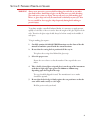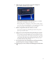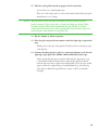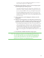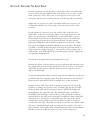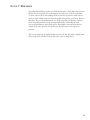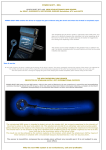
1
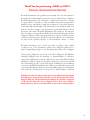
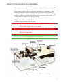
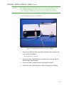
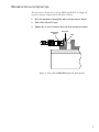
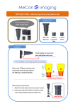
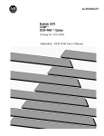
GKM and GKM-2 Glass Knife Maker Instruction Manual April, 2010 Boeckeler Inst r ument s, Inc. 4 650 S But t er field D r ive Tucso n, AZ 85714-3403 520-745-0001 800-552-2262 F ax: 520-745-0004 w ww.r mcpro duct s.co m www.bo eckeler.co m info @bo eckeler.co m Part No. 0209 Thank You for purchasing a GKM or GKM-2 Boeckeler Instruments Product Warranty Boeckeler Instruments, Inc. products are warranted to be free from defects in materials and workmanship for a period of one year from the date of delivery. Boeckeler Instruments, Inc. will repair or replace and return free of charge any part which is returned to its factory within said period, transportation prepaid by user, and which is found upon inspection to have been defective in materials and workmanship. This warranty does not include normal wear from use, nor does it apply to any instrument or part which has been altered by anyone other than a Boeckeler Instruments, Inc. employee. The warranty does not apply to any instrument which has been damaged through accident, negligence, failure to follow operating instructions, the use of electric currents or circuits other than those specified on the plate affixed to the instrument, use beyond the specified capacity of the instrument, misuse or abuse. Boeckeler Instruments, Inc. reserves the right to change, alter, modify or improve any of its instruments without any obligation whatsoever to make corresponding changes to any instrument previously sold or shipped. The foregoing obligations are in lieu of all other obligations and liabilities including negligence and all warranties of merchantability or otherwise, expressed or implied in fact or by law, and state our entire and exclusive liability and buyer’s exclusive remedy for any claim or damages in connection with the sale or furnishing of goods or parts, their design, suitability for use, installation or operation. Boeckeler Instruments, Inc. will in no event be liable for any special or consequential damages whatsoever, and our liability under no circumstances will exceed the contract price for the goods for which liability is claimed. Should you need service for your unit, please contact Boeckeler Instruments through any of the means listed on the cover of this manual. We will be happy to help you. The model and serial number of each unit is registered at the factory when the unit is shipped. Please have these numbers handy when you call us, or include them in any written correspondence. 2 Before You Start Using Your Glass Knife Maker The information contained in this manual has been verified and validated and is believed to be accurate for the intended use of the instrument. If the instrument or procedures are used for purposes different than the capabilities specified herein, confirmation of their validity and suitability should be obtained from an appropriate product specialist at Boeckeler Instruments. Otherwise, Boeckeler Instruments does not guarantee results and assumes no obligation or liability. This publication is not a license to operate under, nor a recommendation to infinge upon any process patents. NOTES, CAUTIONS, and WARNINGS within the text of this manual are used to emphasize important and critical instructions. WARNING A warning informs you of a hazard or an unsafe practice that could result in personal injury or effect the operators health. CAUTION A caution informs the operator of an unsafe practice that could result in the damage of the equipment. NOTE Notes are used to highlight essential information. Figure 1: Diagram of the GKM Glass Knife Maker 3 Attaching the Digital Readout (GKM-2 Only) NOTE The GKM model glass knife maker does not have a digital readout. If you have a GKM, simply ignore all references in this manual to the digital readout. The glass knife maker unit functions identically in both models. To attach the digital readout to the GKM-2: Figure 2: Digital Readout Connections for the GKM-2 1. Connect one end of the db-9 serial cable(included) to the serial port (A) on the back of the GKM-2. Hand tighten the connector. 2. Connect the other end of the db-9 serial cable to the serial port (B) on the back of the digital readout. 3. Connect the power cord to the back of the digital readout(C). 4. Connect the other end of the power cord to an appropriate wall plug. 4 Micrometer Installation Instructions The micrometers, identical for both the GKM and GKM-2, are shipped in separate containers. Unpack and install them as follows: 1. Insert the micrometer through the hole in the micrometer mount. 2. Push it forward until it stops. 3. Tighten the set screw. Found on the back of the micrometer holder. Set Screw Micrometer Scale 45 Hole 0 0 5 Figure 3: View of the GKM/GKM-2 from the front left side. 5 Section 1: Description Of The Instrument Glass knives for Ultramicrotomy and Cryoultramicrotomy are made from special process glass strips which may be purchased from Boeckeler Instruments in three thicknesses: 6mm, 8mm and 12mm. The strips are supplied in nominal lengths of 200mm and 400mm. The glass strips should be first cleaned with detergent, rinsed and then dried. The strips are then placed on the top of the instrument, scored and then broken so as to yield 25mm glass squares. The squares are then scored diagonally to just slightly to the sides of opposite corners and then broken so as to produce two glass triangles with 45° angle cutting edges. This instrument is designed to produce glass knives by an adaptation of the new Balanced Break method of Griffiths, et al. With this method, glass squares are first produced from glass strips by breaking the strip in half and each succesive strip in half until glass squares are produced. In this manner, each break is as nearly per pendicular as possible. Using older methods with other instruments, the squares were broken off the end of a longer strip. This resulted in unequal pressure being applied on each side of the score, due to the greater weight of the longer side of the strip. Consequently the edges were not always perpendicular. To make knives, the squares are scored nearly exactly diagonally such that the score lines are pointing only slightly to the right of one corner and to the left of the opposite corner. This method produces knives with an included angle as close to 45° as possible. This gives knives of maximum sharpness. If the score is pointing too far to the left or right of the opposite corners, the final break will go to the nearest edge, rather than towards the corner, and the real included angle will be significantly greater than 45°. This would produce a knife edge which is too blunt, especially for cryoultramicrotomy. The digital readout included with the GKM-2 makes it much easier to get consistently high-quality glass knives from all your breaks. The readout indicates the "load" (Mechanical engineering term meaning force or weight on a structure.) on the glass strip or square at any particular time. By noting the readout numbers as you start using the GKM-2, you will soon have consistently high-quality, repeatable breaks. With the GKM model, it is necessary to estimate the pressure applied. 6 Section 2: Cleaning The Glass Strips The glass strips should be carefully cleaned with a good quality mild detergent such as used for cleaning fine crystal glassware. Wear rubber gloves and be careful handling the glass to avoid cutting your hands with the sharp edges. Use a soft sponge to clean off any residue. Rinse with distilled water and dry with a good quality lint-free laboratory tissue. 7 Section 3: Preparing 25mm Glass Squares WARNING Always wear protective eyewear while breaking glass with this or any other glass knife maker. Small chips of glass can fly into your eyes while breaking glass and cause serious eye injury. Do not rub your eyes while making glass knives, as glass chips can easily be transferred accidentally to your eyes. Also be very carefull to clean up glass chips frequently during knife making to prevent injury. To produce straight, controlled, balanced breaks, it is necessary to apply pressure equally to both sides of the score and to have the weight of the glass equal on both sides. Therefore the glass strips should always be broken exactly in the middle of each piece. To begin making glass squares: 1. Carefully examine the labeled GKM illustration near the front of the this manual to familarize yourself with the control locations. 2. Be sure that the scoring shaft is positioned all the way in. This places the scoring wheel behind the glass strip. 3. Select the proper score. Rotate the score selector so that the number 1 lines up with the score index. 4. Take a freshly cleaned glass strip and place it on the top of the instrument such that its right edge stops against the 200mm or 100mm stop, depending upon the length of the strip. The stop should be flipped forward. The manufacturer’s score marks should face upward. 5. Be sure that the back edge is firmly against the rear positioner so that the score will be made exactly at a 90° angle. Hold in postion with your hand. 8 6. Tighten the glass strip in position by rotating the clamping lever counterclockwise until firm contact is made. On the GKM-2, the numbers on the readout will begin to rise slightly, indicating the load being placed on the glass strip. When breaking 8mm or 12mm glass, you may wish to produce a deeper score. To do this, raise the breaking lever to a point approximately 10 mm above the top surface of the instrument to pre-stress the glass. 7. Pull the scoring shaft forward with a smooth, even stroke. Leave in the forward position. Should the glass break at this point the glass was pre-stressed too hard. 8. Apply pressure to the anvil by slowly moving the breaking lever upward. As “slow breaks” often yield straighter, more stress-free breaks, move the lever up only until resistance is felt and then watch until the score begins to spread upward through the glass and the glass breaks. This will require some practice until you have acquired the right “feel”. However, even faster breaks will often yield good edges. 9. Once the glass breaks, lower the breaking lever and lift up the breaking arm from the glass by rotating the clamping lever clockwise. 10. Pull the glass pieces away carefully to avoid damaging the freshly broken edge. 9 11. Push the scoring shaft inwards to prepare for the next break. You now have two equal length strips. Place one of the strips aside on a clean cloth until needed. Always keep the manufacturer’s score sideup. NOTE The top surface of the instrument should be brushed off with the paint brush to remove all glass chips after each glass breaking operation. Failure to remove all glass chips before positioning the glass for the next break could result in uneven pressure and a poor quality break (fracture edge). Do not brush glass chips into the scoring shaft slot. 12. Flip the 100mm or 50mm stop down. 13. Place the glass strip on the instrument so that the right edge is against the stop. Firmly position the glass strip against the back positioner and repeat steps 5 through 10. 14. Continue breaking the glass strips in a symmetrical manner, such that the right edge stops against the 100mm, 50mm and finally 25mm stops. Always break each glass piece exactly in half using the appropriate stop, so that all the breaks are balanced. Note that the last square produced from the left end of the original strip will probably not be an exact, usable square, unless the original strip was exactly 400mm long. 16-inch long glass strips are 406mm long and the last “square” will be an unusable rectangle. 10 Section 4: Making Knives From The Squares The glass squares are scored nearly exactly diagonally to produce two glass knives from each square. The glass squares are positioned diagonally in the knifemaker. A knife edge should be produced just to one side of the top corner and just to the other side of the bottom corner. If the score were exactly diagonal, the break would occur right through the top and bottom corners of the square and no useful cutting edges would be produced. Since the glass knife maker scores and breaks symmetrically, it may be adjusted to form knife edges in either the upper left and the lower right corners, for example, or the upper right and lower left. Just be consistent in order to simplify adjustments. 1. Be sure the scoring shaft is pushed all the way in. This places the scoring wheel behind the glass. 2. Rotate the score selector to number 2. 3. Examine the glass square and determine which sides were freshly broken and which were broken by the manufacturer. Most microtomists prefer to make the knife edges on the edges which were produced by the manufacturer, since these edges are very nearly perpendicular and have minimal stress lines. 4. Position the glass square so the edges are oriented to become the side where the knife edge will be formed and the manufacturer’s scored edges face upward. 5. Pull back on the front positioner retract knob and flip over the catch (located to the left of this knob). 6. Insert the glass square. The far corner of the glass square should be placed in the notched space of the rear positioner. The corner nearest the operator should be held in position by the notch on the front positioner. 7. Flip back the catch and release the spring-loaded retract knob to secure the glass square between the notches of the front and rear positioners. This gives a positive and reproducible alignment of the squares. 8. Lower the breaking anvil over the glass by rotating the clamping lever counterclockwise. The digital readout numbers will begin to rise on the GKM-2. 9. Pull the scoring shaft towards you with a smooth motion to produce an even score. 11 You may pre-stress the glass by lifting the breaking lever (see Section 3 #6) if you need a deeper score for thicker glass. 10. Slowly lift on the breaking lever until you see the score begin to spread upward through the glass, forming a fracture. Stop and let the glass break by itself. This produces a break by the “slow break method”, which is generally regarded as producing the best knives. If you are using the GKM-2, make a note of the digital readout number. The readout typically indicates around "60" for the correct load. Some initial testing will help you find the best load for your instrument. Once you discover it, you will be able to make consistent high-quality breaks on all your glass strips. 11. After the glass breaks, turn the clamping lever clockwise to raise the breaking anvil. 12. Pull back on the front positioner retract knob with one hand and secure it with the catch, carefully rotating the two halves of the glass square with the other hand until they can be slid out from under the breaking arm. The actual knife edge should be about 1 mm or less away from the corner of the original glass square. This distance can be evaluated by examining the opposing edge of the opposite piece of glass. The opposing edge has a “shelf ” rather than a knife edge, since only one knife edge can be formed at each corner. The width of this shelf should be carefully evaluated. Knives for sectioning plastic resins should have shelves about 0.5 to 1 mm wide. 13. Two usable knives should be formed from each glass square. Note For cryoultramicrotomy knives the shelf should be only 0.2 mm or less, since the smaller the shelf is, the more closely the knife edge approaches a true 45° angle. This will produce a knife which is maximally sharp for cryoultramicrotomy of frozen tissue, but such a knife might dull too quickly for use with plastic resin embedded specimens. 12 Section 5: Evaluating The Glass Knives Examine the shelves on both glass pieces to determine if the correct shelf width was formed for each opposing knife edge. If the shelves were too wide, or if the break occurred too close to the corner, or even right across the corner, or the wrong side, then the front or back positioners or both may need to be adjusted. Adjust only one positioner at a time. Determine which corner was most out of alignment, and take note of the setting on the micrometer scale for that positioner. Decide which way you want to move the notch in order to shift the score mark relative to the corner of the glass square. To move the positioner to the right, rotate the micrometer knob clockwise. You should be able to observe the movement of the micrometer shaft and the positioner to determine that you are moving the positioner in the direction desired. The micrometer is calibrated in millimeters and the smallest graduations are 0.01 mm = 1 0um. Very precise and highly reproducible adjustments are easily made. This makes it possible to carefully monitor the effects of moving the positioner and also to return to previous settings if desired. To start with, move the positioner only a small amount, as the shelf will shift by a somewhat greater amount. Tighten the corresponding clamping knob. Now break another glass knife by repeating the above steps. Examine the shelves of the new knives you have just broken and determine if you have adjusted the positioner in the right direction. If you are close to the desired shelf width, you may want to adjust the positioner for the opposite corner to improve its shelf width. Continue breaking knives until you have both positioners adjusted to produce two good knife edges from each glass square. Record the micrometer scale settings for future reference, particularly if there are multiple users of this instrument. Examine both the knife edge and the counterpiece shelf from each corner. Be careful not to damage the opposite corner, as its knife edge may also be usable. Ideally the knife edge and its counterpiece edge should be both straight and perpendicular to the edge of the glass. The usable knife edge is generally in the middle of the knife edge or towards the top of the curved stress mark. As mentioned above, the shelf on the counterpiece should be less than 0.2mm wide if the knives are to be used for cryoultramicrotomy. If it is larger, the “break” (fracture line) tends to wander away from the direction of the score and goes towards the nearest edge, rather than towards the corner. This can result in a knife edge whose real included angle at the very edge may be as much as 10° or more greater than 45°. Such a knife will be relatively blunt and will not cut the thinnest ultrathin sections. It would also be prone to cause section compression. 13 Section 6: Troubleshooting Problem: Slanted or curved breaks (edges not perpendicular to the flat surface). Solutions: May be due to dirty glass, or glass chips on the surface of the instru ment. This surface should be brushed clean with a small paint brush after each break to clean away any glass chips which may have been left from the previous break. This problem could also be due to poor quality glass, which has internal stresses. Use quality Ultramicrotomy Glass, see Ordering Information. 14 Section 7: Maintenance Your Glass Knife Maker requires very little maintenance. Glass chips may however fall into the scoring shaft groove and impair smooth action of the scoring shaft. To clean, remove the screws holding the front and rear positioners, then remove the four screws which secure the slotted top plate beneath the positioners. Remove this plate. The scoring mechanism is now easily accessible for cleaning. Unscrew the scoring shaft and remove the scoring wheel holder. Clean all parts with acetone and relubricate with a light grease. Reassemble. Since the micrometers remain in the same position, the positioners should return to their previous position. The scoring wheel can be replaced when necessary by this procedure. Simply push the scoring wheel axle thru its hole and insert a new scoring wheel. 15 Section 8: References 1 Griffiths, G., Simons, K., Warren, G. and Tokuyasu, K.T. (1983). Immunoelectron microscopy using thin, frozen sections: application to studies of the intracellular transport of Semliki Forest virus spike glycoproteins. Methods Enzymol. 96, 435-450. 16 Section 9: Ordering Information Ultramicrotomy Glass Strips: Part No. 315626 12mm x 1" x 8" (25.4 x 203mm), package of 16 pieces Part No. 316995 6mm x 1" x 16" (25.4 x 406mm), package of 30 pieces Part No. 316996 8mm x 1" x 16" (25.4 x 406mm), package of 24 pieces 17