1
®
Pointmaker PVI-X90
Presentation System
User’s Manual
®
™
Pointmaker PVI - X90
Presentation System
User’s Manual
Copyright
© 2007 by Boeckeler Instruments, Inc.,
4650 S. Butter field Drive, Tucson, AZ 85714; (520)745-0001
No par t of this publication may be reproduced, transmitted, transcribed, stored in a retrieval
system or translated into any language in any form by any means without the expressed written
permission of Boeckeler Instruments, Inc.
Pointmaker® and Boeckeler® are registered trademarks of Boeckeler Instruments, Inc., of
Tucson, Arizona. All other trademarks and registered trademarks are the property of their
respective companies.
P/N 100207
CONTENTS
SECTION ONE:
GETTING STARTED . . . . . . . . . . . . . . . . . . . . . . . . . . . . . . . . . . . . . . . . . . . . . . . . . . 1
Introduction. . . . . . . . . . . . . . . . . . . . . . . . . . . . . . . . . . . . . . . . . . . . . . . . . . . . . . . . . . . . . . . . . . . . 3
A Very Flexible Pointmaker . . . . . . . . . . . . . . . . . . . . . . . . . . . . . . . . . . . . . . . . . . . . . . . . . . . . . 3
Features . . . . . . . . . . . . . . . . . . . . . . . . . . . . . . . . . . . . . . . . . . . . . . . . . . . . . . . . . . . . . . . . . . . . . . . 9
Peripheral Devices . . . . . . . . . . . . . . . . . . . . . . . . . . . . . . . . . . . . . . . . . . . . . . . . . . . . . . . . . . . . . 11
Digitizing Tablet . . . . . . . . . . . . . . . . . . . . . . . . . . . . . . . . . . . . . . . . . . . . . . . . . . . . . . . . . . . . . 12
Light Pen . . . . . . . . . . . . . . . . . . . . . . . . . . . . . . . . . . . . . . . . . . . . . . . . . . . . . . . . . . . . . . . . . . . 15
Keyboard Controller . . . . . . . . . . . . . . . . . . . . . . . . . . . . . . . . . . . . . . . . . . . . . . . . . . . . . . . . . . 17
Touch Screen . . . . . . . . . . . . . . . . . . . . . . . . . . . . . . . . . . . . . . . . . . . . . . . . . . . . . . . . . . . . . . . 20
Mouse-type Devices . . . . . . . . . . . . . . . . . . . . . . . . . . . . . . . . . . . . . . . . . . . . . . . . . . . . . . . . . . 22
Installation. . . . . . . . . . . . . . . . . . . . . . . . . . . . . . . . . . . . . . . . . . . . . . . . . . . . . . . . . . . . . . . . . . . . 25
Connecting Video Sources . . . . . . . . . . . . . . . . . . . . . . . . . . . . . . . . . . . . . . . . . . . . . . . . . . . . . 25
Connecting Audio (requires COMM-4(A) board) . . . . . . . . . . . . . . . . . . . . . . . . . . . . . . . . . . . 26
Connecting Control Devices . . . . . . . . . . . . . . . . . . . . . . . . . . . . . . . . . . . . . . . . . . . . . . . . . . . . 27
Connecting Displays . . . . . . . . . . . . . . . . . . . . . . . . . . . . . . . . . . . . . . . . . . . . . . . . . . . . . . . . . . 31
Activation. . . . . . . . . . . . . . . . . . . . . . . . . . . . . . . . . . . . . . . . . . . . . . . . . . . . . . . . . . . . . . . . . . . . . 33
Power Up . . . . . . . . . . . . . . . . . . . . . . . . . . . . . . . . . . . . . . . . . . . . . . . . . . . . . . . . . . . . . . . . . . 33
Menu Basics . . . . . . . . . . . . . . . . . . . . . . . . . . . . . . . . . . . . . . . . . . . . . . . . . . . . . . . . . . . . . . . . 33
Built-in Help Messages. . . . . . . . . . . . . . . . . . . . . . . . . . . . . . . . . . . . . . . . . . . . . . . . . . . . . . . . 36
PVI-PC20 Software Installation (PC only). . . . . . . . . . . . . . . . . . . . . . . . . . . . . . . . . . . . . . . . . 37
SECTION TWO:
ANNOTATION MENU . . . . . . . . . . . . . . . . . . . . . . . . . . . . . . . . . . . . . . . . . . . . . . . . 39
Annotation Settings . . . . . . . . . . . . . . . . . . . . . . . . . . . . . . . . . . . . . . . . . . . . . . . . . . . . . . . . . . . . 41
Pointers . . . . . . . . . . . . . . . . . . . . . . . . . . . . . . . . . . . . . . . . . . . . . . . . . . . . . . . . . . . . . . . . . . . . 41
Selecting an Erase Method . . . . . . . . . . . . . . . . . . . . . . . . . . . . . . . . . . . . . . . . . . . . . . . . . . . . . 42
Selecting a Line Style . . . . . . . . . . . . . . . . . . . . . . . . . . . . . . . . . . . . . . . . . . . . . . . . . . . . . . . . . 43
Customizing the Color Palette . . . . . . . . . . . . . . . . . . . . . . . . . . . . . . . . . . . . . . . . . . . . . . . . . . 44
Setting an Overlay Brightness Level . . . . . . . . . . . . . . . . . . . . . . . . . . . . . . . . . . . . . . . . . . . . . 46
Changing Pen Proximity . . . . . . . . . . . . . . . . . . . . . . . . . . . . . . . . . . . . . . . . . . . . . . . . . . . . . . . 48
Pointer Toggle. . . . . . . . . . . . . . . . . . . . . . . . . . . . . . . . . . . . . . . . . . . . . . . . . . . . . . . . . . . . . . . 48
Contents
SECTION THREE:
DISPLAY AND AUDIO MENUS . . . . . . . . . . . . . . . . . . . . . . . . . . . . . . . . . . . . . . . . . 51
The Display Menu . . . . . . . . . . . . . . . . . . . . . . . . . . . . . . . . . . . . . . . . . . . . . . . . . . . . . . . . . . . . . 53
Selecting a Marking Background . . . . . . . . . . . . . . . . . . . . . . . . . . . . . . . . . . . . . . . . . . . . . . . . 53
Video Setup . . . . . . . . . . . . . . . . . . . . . . . . . . . . . . . . . . . . . . . . . . . . . . . . . . . . . . . . . . . . . . . . 54
Turning Zap Icon On/Off . . . . . . . . . . . . . . . . . . . . . . . . . . . . . . . . . . . . . . . . . . . . . . . . . . . . . . 63
Turning Touch Screen Function Areas On/Off . . . . . . . . . . . . . . . . . . . . . . . . . . . . . . . . . . . . . 64
Control Panels (UTROL Option) . . . . . . . . . . . . . . . . . . . . . . . . . . . . . . . . . . . . . . . . . . . . . . . . 65
The Audio Menu. . . . . . . . . . . . . . . . . . . . . . . . . . . . . . . . . . . . . . . . . . . . . . . . . . . . . . . . . . . . . . . 67
Adjusting Gain . . . . . . . . . . . . . . . . . . . . . . . . . . . . . . . . . . . . . . . . . . . . . . . . . . . . . . . . . . . . . . 67
SECTION FOUR:
COMM PORT DEVICES MENU . . . . . . . . . . . . . . . . . . . . . . . . . . . . . . . . . . . . . . . . . 69
Comm Port Operations . . . . . . . . . . . . . . . . . . . . . . . . . . . . . . . . . . . . . . . . . . . . . . . . . . . . . . . . . 71
Controllers Requiring Calibration . . . . . . . . . . . . . . . . . . . . . . . . . . . . . . . . . . . . . . . . . . . . . . . 71
Serial Port Settings . . . . . . . . . . . . . . . . . . . . . . . . . . . . . . . . . . . . . . . . . . . . . . . . . . . . . . . . . . . 75
Setting the Tablet Template . . . . . . . . . . . . . . . . . . . . . . . . . . . . . . . . . . . . . . . . . . . . . . . . . . . . 81
SECTION FIVE:
USING MARKERS . . . . . . . . . . . . . . . . . . . . . . . . . . . . . . . . . . . . . . . . . . . . . . . . . . . 85
Overview . . . . . . . . . . . . . . . . . . . . . . . . . . . . . . . . . . . . . . . . . . . . . . . . . . . . . . . . . . . . . . . . . . . . . 87
Basic Marking Concepts . . . . . . . . . . . . . . . . . . . . . . . . . . . . . . . . . . . . . . . . . . . . . . . . . . . . . . 87
Assigning Marker Appearance . . . . . . . . . . . . . . . . . . . . . . . . . . . . . . . . . . . . . . . . . . . . . . . . . . . 89
Assigning Marker Colors . . . . . . . . . . . . . . . . . . . . . . . . . . . . . . . . . . . . . . . . . . . . . . . . . . . . . . 89
Assigning Line Styles. . . . . . . . . . . . . . . . . . . . . . . . . . . . . . . . . . . . . . . . . . . . . . . . . . . . . . . . . 90
Selecting Pointers . . . . . . . . . . . . . . . . . . . . . . . . . . . . . . . . . . . . . . . . . . . . . . . . . . . . . . . . . . . . 91
Turning the Active Pointer On/Off . . . . . . . . . . . . . . . . . . . . . . . . . . . . . . . . . . . . . . . . . . . . . . 91
Marking. . . . . . . . . . . . . . . . . . . . . . . . . . . . . . . . . . . . . . . . . . . . . . . . . . . . . . . . . . . . . . . . . . . . . . 93
Entering the Marking Mode . . . . . . . . . . . . . . . . . . . . . . . . . . . . . . . . . . . . . . . . . . . . . . . . . . . . 93
Pointing . . . . . . . . . . . . . . . . . . . . . . . . . . . . . . . . . . . . . . . . . . . . . . . . . . . . . . . . . . . . . . . . . . . 93
Drawing . . . . . . . . . . . . . . . . . . . . . . . . . . . . . . . . . . . . . . . . . . . . . . . . . . . . . . . . . . . . . . . . . . . 94
Typing Text Labels . . . . . . . . . . . . . . . . . . . . . . . . . . . . . . . . . . . . . . . . . . . . . . . . . . . . . . . . . . 95
Sizing and Anchoring Frames . . . . . . . . . . . . . . . . . . . . . . . . . . . . . . . . . . . . . . . . . . . . . . . . . . 96
Stamping the Date/Time. . . . . . . . . . . . . . . . . . . . . . . . . . . . . . . . . . . . . . . . . . . . . . . . . . . . . . . 97
Clearing Markers . . . . . . . . . . . . . . . . . . . . . . . . . . . . . . . . . . . . . . . . . . . . . . . . . . . . . . . . . . . . . 101
Clearing All Markers . . . . . . . . . . . . . . . . . . . . . . . . . . . . . . . . . . . . . . . . . . . . . . . . . . . . . . . . 101
Page ii - Pointmaker PVI-X90 Presentation System
Boeckeler Instruments, Inc.
Contents
Undoing a Marker . . . . . . . . . . . . . . . . . . . . . . . . . . . . . . . . . . . . . . . . . . . . . . . . . . . . . . . . . . . 101
Erasing Markers . . . . . . . . . . . . . . . . . . . . . . . . . . . . . . . . . . . . . . . . . . . . . . . . . . . . . . . . . . . . 102
Using The Chalkboard . . . . . . . . . . . . . . . . . . . . . . . . . . . . . . . . . . . . . . . . . . . . . . . . . . . . . . . . . 105
Activating the Chalkboard . . . . . . . . . . . . . . . . . . . . . . . . . . . . . . . . . . . . . . . . . . . . . . . . . . . . 105
Manipulating Overlays. . . . . . . . . . . . . . . . . . . . . . . . . . . . . . . . . . . . . . . . . . . . . . . . . . . . . . . . . 107
Paging Through Overlays . . . . . . . . . . . . . . . . . . . . . . . . . . . . . . . . . . . . . . . . . . . . . . . . . . . . . 107
Turning Off the Marker Overlay. . . . . . . . . . . . . . . . . . . . . . . . . . . . . . . . . . . . . . . . . . . . . . . . 108
SECTION SIX:
PVI-PC20 SOFTWARE CONFIGURATION AND USE . . . . . . . . . . . . . . . . . . . . . . . 111
Overview . . . . . . . . . . . . . . . . . . . . . . . . . . . . . . . . . . . . . . . . . . . . . . . . . . . . . . . . . . . . . . . . . . . . 113
Setup. . . . . . . . . . . . . . . . . . . . . . . . . . . . . . . . . . . . . . . . . . . . . . . . . . . . . . . . . . . . . . . . . . . . . . . . 115
Installation. . . . . . . . . . . . . . . . . . . . . . . . . . . . . . . . . . . . . . . . . . . . . . . . . . . . . . . . . . . . . . . . . 115
Connecting/Disconnecting . . . . . . . . . . . . . . . . . . . . . . . . . . . . . . . . . . . . . . . . . . . . . . . . . . . . . . 119
Establishing Communications with the Pointmaker . . . . . . . . . . . . . . . . . . . . . . . . . . . . . . . . . 119
Closing Communications with the Pointmaker . . . . . . . . . . . . . . . . . . . . . . . . . . . . . . . . . . . . 119
Setting Properties . . . . . . . . . . . . . . . . . . . . . . . . . . . . . . . . . . . . . . . . . . . . . . . . . . . . . . . . . . . . . 121
Button Properties . . . . . . . . . . . . . . . . . . . . . . . . . . . . . . . . . . . . . . . . . . . . . . . . . . . . . . . . . . . 121
Setting Save Properties . . . . . . . . . . . . . . . . . . . . . . . . . . . . . . . . . . . . . . . . . . . . . . . . . . . . . . . 124
Setting Print Defaults . . . . . . . . . . . . . . . . . . . . . . . . . . . . . . . . . . . . . . . . . . . . . . . . . . . . . . . . 126
Calibrating the PC with the Pointmaker . . . . . . . . . . . . . . . . . . . . . . . . . . . . . . . . . . . . . . . . . . 127
Calibrating the PC Screen with the Pointmaker Overlays . . . . . . . . . . . . . . . . . . . . . . . . . . . . 127
Switching Tablet Modes . . . . . . . . . . . . . . . . . . . . . . . . . . . . . . . . . . . . . . . . . . . . . . . . . . . . . . . . 131
PC Control and Pointmaker Control . . . . . . . . . . . . . . . . . . . . . . . . . . . . . . . . . . . . . . . . . . . . . 131
SECTION SEVEN:
COMMANDS FOR RS-232 CONTROL . . . . . . . . . . . . . . . . . . . . . . . . . . . . . . . . . . . 133
Introduction. . . . . . . . . . . . . . . . . . . . . . . . . . . . . . . . . . . . . . . . . . . . . . . . . . . . . . . . . . . . . . . . . . 135
X-Y Coordinate Grid . . . . . . . . . . . . . . . . . . . . . . . . . . . . . . . . . . . . . . . . . . . . . . . . . . . . . . . . 135
Commands. . . . . . . . . . . . . . . . . . . . . . . . . . . . . . . . . . . . . . . . . . . . . . . . . . . . . . . . . . . . . . . . . . . 137
(A) Autodetect Monitor . . . . . . . . . . . . . . . . . . . . . . . . . . . . . . . . . . . . . . . . . . . . . . . . . . . . . . 137
(B) Background. . . . . . . . . . . . . . . . . . . . . . . . . . . . . . . . . . . . . . . . . . . . . . . . . . . . . . . . . . . . . 137
(C) Active Marker Off/On . . . . . . . . . . . . . . . . . . . . . . . . . . . . . . . . . . . . . . . . . . . . . . . . . . . . 137
(CA) Calibrations . . . . . . . . . . . . . . . . . . . . . . . . . . . . . . . . . . . . . . . . . . . . . . . . . . . . . . . . . . . 138
(CE) Color Enable. . . . . . . . . . . . . . . . . . . . . . . . . . . . . . . . . . . . . . . . . . . . . . . . . . . . . . . . . . . 138
(CL) Clear . . . . . . . . . . . . . . . . . . . . . . . . . . . . . . . . . . . . . . . . . . . . . . . . . . . . . . . . . . . . . . . . . 139
Boeckeler Instruments, Inc.
Pointmaker PVI-X90 Presentation System - Page iii
Contents
(CM) Marker Move . . . . . . . . . . . . . . . . . . . . . . . . . . . . . . . . . . . . . . . . . . . . . . . . . . . . . . . . . 139
(CS) Color Selection . . . . . . . . . . . . . . . . . . . . . . . . . . . . . . . . . . . . . . . . . . . . . . . . . . . . . . . . 139
(DL) Draw Line . . . . . . . . . . . . . . . . . . . . . . . . . . . . . . . . . . . . . . . . . . . . . . . . . . . . . . . . . . . . 140
(DP) Drop Marker . . . . . . . . . . . . . . . . . . . . . . . . . . . . . . . . . . . . . . . . . . . . . . . . . . . . . . . . . . 140
(E) Echo . . . . . . . . . . . . . . . . . . . . . . . . . . . . . . . . . . . . . . . . . . . . . . . . . . . . . . . . . . . . . . . . . . 140
(EM) Erase Method . . . . . . . . . . . . . . . . . . . . . . . . . . . . . . . . . . . . . . . . . . . . . . . . . . . . . . . . . 141
(FS) Frame Size . . . . . . . . . . . . . . . . . . . . . . . . . . . . . . . . . . . . . . . . . . . . . . . . . . . . . . . . . . . . 141
(FT) Frame Type . . . . . . . . . . . . . . . . . . . . . . . . . . . . . . . . . . . . . . . . . . . . . . . . . . . . . . . . . . . 141
(I) Marker Intensity or Brightness . . . . . . . . . . . . . . . . . . . . . . . . . . . . . . . . . . . . . . . . . . . . . . 141
(IM) Identify Mode for Multiple Users . . . . . . . . . . . . . . . . . . . . . . . . . . . . . . . . . . . . . . . . . . 142
(L) Line Style . . . . . . . . . . . . . . . . . . . . . . . . . . . . . . . . . . . . . . . . . . . . . . . . . . . . . . . . . . . . . . 142
(M) Input Port and Chalkboard Generation . . . . . . . . . . . . . . . . . . . . . . . . . . . . . . . . . . . . . . . 142
(MO) Video Output . . . . . . . . . . . . . . . . . . . . . . . . . . . . . . . . . . . . . . . . . . . . . . . . . . . . . . . . . 147
(O) Offset for Light Pen . . . . . . . . . . . . . . . . . . . . . . . . . . . . . . . . . . . . . . . . . . . . . . . . . . . . . . 148
(PA) Pass-through . . . . . . . . . . . . . . . . . . . . . . . . . . . . . . . . . . . . . . . . . . . . . . . . . . . . . . . . . . 148
(PT) Pointer Type. . . . . . . . . . . . . . . . . . . . . . . . . . . . . . . . . . . . . . . . . . . . . . . . . . . . . . . . . . . 148
(PX) Proximity On/Off. . . . . . . . . . . . . . . . . . . . . . . . . . . . . . . . . . . . . . . . . . . . . . . . . . . . . . . 149
(R) Restart Pointmaker. . . . . . . . . . . . . . . . . . . . . . . . . . . . . . . . . . . . . . . . . . . . . . . . . . . . . . . 150
(S) Date/Time Marker . . . . . . . . . . . . . . . . . . . . . . . . . . . . . . . . . . . . . . . . . . . . . . . . . . . . . . . 150
(SA) Audio Settings . . . . . . . . . . . . . . . . . . . . . . . . . . . . . . . . . . . . . . . . . . . . . . . . . . . . . . . . . 150
(SC) Scaled Video Adjustments. . . . . . . . . . . . . . . . . . . . . . . . . . . . . . . . . . . . . . . . . . . . . . . . 151
(SR) Scaled Video Adjustments - Relative . . . . . . . . . . . . . . . . . . . . . . . . . . . . . . . . . . . . . . . 152
(SU) Menu System Visibility . . . . . . . . . . . . . . . . . . . . . . . . . . . . . . . . . . . . . . . . . . . . . . . . . . 153
(SUG) Graphics Display . . . . . . . . . . . . . . . . . . . . . . . . . . . . . . . . . . . . . . . . . . . . . . . . . . . . . 154
(SUM) Menu System . . . . . . . . . . . . . . . . . . . . . . . . . . . . . . . . . . . . . . . . . . . . . . . . . . . . . . . . 154
(SUO) Menu System Display. . . . . . . . . . . . . . . . . . . . . . . . . . . . . . . . . . . . . . . . . . . . . . . . . . 154
(T) Text Label . . . . . . . . . . . . . . . . . . . . . . . . . . . . . . . . . . . . . . . . . . . . . . . . . . . . . . . . . . . . . 155
(TA) Template Change. . . . . . . . . . . . . . . . . . . . . . . . . . . . . . . . . . . . . . . . . . . . . . . . . . . . . . . 156
(TC) Touch Screen Corner Control . . . . . . . . . . . . . . . . . . . . . . . . . . . . . . . . . . . . . . . . . . . . . 156
(U) Undo/Erase. . . . . . . . . . . . . . . . . . . . . . . . . . . . . . . . . . . . . . . . . . . . . . . . . . . . . . . . . . . . . 156
(V) Select an Overlay . . . . . . . . . . . . . . . . . . . . . . . . . . . . . . . . . . . . . . . . . . . . . . . . . . . . . . . . 157
(Z) Zap Icon . . . . . . . . . . . . . . . . . . . . . . . . . . . . . . . . . . . . . . . . . . . . . . . . . . . . . . . . . . . . . . . 157
APPENDIX . . . . . . . . . . . . . . . . . . . . . . . . . . . . . . . . . . . . . . . . . . . . . . . . . . . . . . . . . A-1
Troubleshooting Guide . . . . . . . . . . . . . . . . . . . . . . . . . . . . . . . . . . . . . . . . . . . . . . . . . . . . . . . . A-3
Page iv - Pointmaker PVI-X90 Presentation System
Boeckeler Instruments, Inc.
Contents
Quick Reference for Devices . . . . . . . . . . . . . . . . . . . . . . . . . . . . . . . . . . . . . . . . . . . . . . . . . . . . A-5
Quick Reference for Digitizing Tablet . . . . . . . . . . . . . . . . . . . . . . . . . . . . . . . . . . . . . . . . . . . A-5
Quick Reference for Light Pen . . . . . . . . . . . . . . . . . . . . . . . . . . . . . . . . . . . . . . . . . . . . . . . . . A-6
Quick Reference for Keyboard . . . . . . . . . . . . . . . . . . . . . . . . . . . . . . . . . . . . . . . . . . . . . . . . . A-6
Quick Reference for Touch Screens and White Boards . . . . . . . . . . . . . . . . . . . . . . . . . . . . . . A-7
Quick Reference for Other Mouse Devices . . . . . . . . . . . . . . . . . . . . . . . . . . . . . . . . . . . . . . . A-8
Monitor Scan Rates . . . . . . . . . . . . . . . . . . . . . . . . . . . . . . . . . . . . . . . . . . . . . . . . . . . . . . . . . . . A-9
Current Compatible Scan Rates . . . . . . . . . . . . . . . . . . . . . . . . . . . . . . . . . . . . . . . . . . . . . . . A-10
Glossary . . . . . . . . . . . . . . . . . . . . . . . . . . . . . . . . . . . . . . . . . . . . . . . . . . . . . . . . . . . . . . . . . . . . A-11
Symbol Font Chart (keyboard). . . . . . . . . . . . . . . . . . . . . . . . . . . . . . . . . . . . . . . . . . . . . . . . . . A-15
Map Font Chart (keyboard) . . . . . . . . . . . . . . . . . . . . . . . . . . . . . . . . . . . . . . . . . . . . . . . . . . . . A-17
RS-232 Pinout (COMM Port-male) . . . . . . . . . . . . . . . . . . . . . . . . . . . . . . . . . . . . . . . . . . . . . A-19
INDEX
Boeckeler Instruments, Inc.
Pointmaker PVI-X90 Presentation System - Page v
SECTION ONE:
GETTING STARTED
Section One: Getting Started
Introduction
INTRODUCTION
A Very Flexible Pointmaker
Powerful
The Pointmaker® PVI-X90 Presentation System by Boeckeler Instruments,
Inc., combines the power of annotation with the features of a video scaler,
switcher, and distribution amplifier. It converts incoming NTSC or PAL television-format video signals to outgoing non-interlaced computer video with
higher scan rates. It handles the input of up to four different a/v components:
e.g. document presenter, VCR, computer, DVD, camera, etc. Any one of those
components can be easily selected for simultaneous display on up to six different computer monitors or projection systems. In addition, it supports up to ten
different pointing/marking/controlling devices (digitizing tablet, touch screen,
light pen, keyboard, mouse devices, etc.) for interacting with the displayed
images.
Figure 1-1: Pointmaker Markings Over a Spreadsheet
Effortless Interaction
This Pointmaker model is especially powerful in classrooms, courtrooms or
meeting environments where a number of people need to mark images during
discussions or presentations. By locating controllers throughout the room and
assigning a unique marker color to each, it’s possible to achieve a smooth
coordination of discussion and marking among all participants.
Boeckeler Instruments, Inc.
Pointmaker PVI-X90 Presentation System - Page 3
Introduction
Section One: Getting Started
Making Your Point
Marker Multiplicity
The large variety of Pointmaker markers further enhances your ability to
emphasize each point to an audience. To begin with, you can assign a variety
of colors to the markers you create. Marker options include: varying line thicknesses (with or without drop shadows), text labels in multiple fonts and sizes,
arrows or pointers of differing shapes and sizes. None of the markers affect the
original images in any way. Markers actually exist on a clear layer above the
image called an “overlay”.
The figure below is a breakout of some digitizing tablet template commands,
illustrating some of the marker options. Each item is available at the click of a
button.
Pointers
Plain & Shadowed Line Styles
Fine
Medium
Bold
Background
Source Video
Chalkboard
Hide / Show
Pointer
Clear All
Markers
Clear Last
Marker
or Erase
Pointer
On/Off
Clear
Undo/Erase
Marker Colors
Figure 1-2: Breakout of PVI-X90 Template Commands
The keyboard controller supports some additional marker types: frames, a
date/time stamp, and straight line drawing. Frames include boxes and circles.
Frames can be sized in advance of a presentation, then used to frame or fill
certain areas of the video image.
Marker Manipulation
One of the most powerful features for presentations using a Pointmaker is the
ability to store up to 25 different marker overlays. They can be created and
saved ahead of time, ready for quick recall during the presentation. For more
on overlays, see “Basic Marking Concepts“ in “Section Five: Using Markers” on page 87, and “Manipulating Overlays” on page 107.
As easily as the markers are created, so are they easily erased: either one at a
time until the screen is clear, or all at once. And, if a video image is not
desired, it’s possible to quickly call up a solid background on the screen and
use it like a chalkboard.
Page 4 - Pointmaker PVI-X90 Presentation System
Boeckeler Instruments, Inc.
Section One: Getting Started
Introduction
Ins and Outs
Making Connections
This diagram illustrates some of the possibilities available to you when you’re
ready to start connecting components to your PVI-X90.
Pointmaker
DT-30 Digitizing Tablets
Touch
Screens
Pointmaker
LP-32 Light Pen
Pointmaker Keyboard
Supports up to 10 markers/controllers in
whatever combination you choose.
(COMM ports 1 and 2 are standard,
an extra 4 or 8 can be added as options)
Use any combination
of up to 4
high-resolution
displays or projectors.
Connect up to 6 A/V components:
2 composite, 2 S-Video (Y/C),
2 computer (VGA)
Figure 1-3: Component Connections
Audio Switching
The PVI-X90 handles audio switching through the optional COMM-4(A)
expansion board. The 6 audio input ports follow the video inputs of the same
name. The board also includes 4 controller ports, and a USB port for use as a
command interface. (See “Section Seven: Commands for RS-232 Control” on
page 133)
Boeckeler Instruments, Inc.
Pointmaker PVI-X90 Presentation System - Page 5
Introduction
Section One: Getting Started
Figure 1-4: Ports of COMM-4(A)
Connection Overview
You can think of the component connections as falling into three groups:
• The video sources which will supply the Pointmaker with the
images you want to mark over.
• The control devices which allow you to select and manipulate the
markers. They also allow you to assign various display settings
within the Pointmaker.
• The displays used to view the final output, such as monitors, projectors, big screens, LCD panels, etc.
Video Source(s)
Controller(s)
via RS-232
PVI-X90
Presentation System
Display(s)
Figure 1-5: PVI-X90 Flow Diagram
In its base configurations, the drawing of lines and markers are controlled
using a digitizing tablet (PVI-X90D), or standard light pen (PVI-X90L). Both
Page 6 - Pointmaker PVI-X90 Presentation System
Boeckeler Instruments, Inc.
Section One: Getting Started
Introduction
models include a keyboard. All PVI-X90 models are also compatible with
most mouse devices and touch screens.
The Pointmaker PVI-X90 is compatible with many common computer standards for VGA, SVGA and Macintosh sources and displays, via HD-15 input/
output connections. Scan rate compatibility ranges from 31.5 kHz to most
SVGA scan rates up to 85 kHz. Most Macintosh scan rates are also handled,
up to 48 kHz.
Boeckeler Instruments, Inc.
Pointmaker PVI-X90 Presentation System - Page 7
Introduction
Page 8 - Pointmaker PVI-X90 Presentation System
Section One: Getting Started
Boeckeler Instruments, Inc.
Section One: Getting Started
Features
FEATURES
•
Video Scaling
Multiple formats of television-style interlaced video are changed to
noninterlaced computer video.
•
Multiple Video Sources
Inputs for 2 composite, 2 S-Video, and 2 computer.
Supports 4:3 aspect ratio.
Easily switches from one input to another.
•
Multiple Video Outputs
Outputs for up to 4 displays (monitors, panels, or projectors).
Output resolutions: 640 X 480, 800 X 600, 1024 X 768, 1280 X
1024
Picture quality adjustments: horizontal & vertical position and
width, brightness, contrast, saturation, and hue.
•
Multiple Controllers
Inputs for up to 10 pointing/marking/controlling devices.
•
Two types of marking tools
Freehand drawing tools in six different line options; fine, medium
and bold, with or without a drop shadow.
Pointers, including arrows, dots and cross hairs, which may be
moved or anchored anywhere on the screen. Arrows may be preset to
point in one of 8 different angles. Dots and cross hairs may be preselected in a small or large size.
•
Four additional marking tools in keyboard model
Straight line drawing mode allows underscoring, mapping or otherwise drawing a straight line. Three different line thicknesses are
available: fine, medium and bold, with or without a drop shadow.
Text can be typed on the video image in one of 6 different fonts, each
available in one or more sizes. You can add a text background to further enhance the text on the video image.
Boeckeler Instruments, Inc.
Pointmaker PVI-X90 Presentation System - Page 9
Features
Section One: Getting Started
Frames in the shapes of circles or boxes may be sized and positioned
to call attention to an area within the frame. Filled frames allow you
to block out portions of the video image, useful in classroom exams
or in blocking out extraneous visuals.
An active date/time label can be placed on the video image to time
an event.
•
The ability to position and anchor a combination of several markers
and drawings on the screen at once.
•
Options for clearing lines and pointers from an overlay all at once,
one at a time (beginning with the most recently anchored marker), or
selectively erased.
•
Ability to attribute a different color to each marker on the screen. Up
to 7 different colors are available for quick access. The color palette
can be minimized by presetting selections in a palette menu.
•
A drop shadow effect may be selected to further optimize the display
of drawn lines.
•
The ability to store up to 25 different marker overlays of Pointmaker
markers so that presentations may be prepared in advance. You can
scroll forward or backward a page at a time or enter an overlay number to quickly display the desired overlay using the keyboard or RS232 commands.
•
Compatibility with VGA, SVGA and Macintosh. (scan rates up to 85
kHz, Macintosh scan rates up to 48 kHz) PC compatibility includes
many nonstandard video scan rates in Windows 95/98. Connections
in/out are HD-15 (high density).
®
•
Sync generation allows the Pointmaker to automatically select the
sync if no live video is desired. Instead of a live image, a solid background appears, ready to be used as you would use a whiteboard or
chalkboard.
•
Keyboard control provides you a quick way to select many of the
menu options without having to go to the menu system. Instead, function keys provide choices for pointer type, background, marker colors, brightness levels, on-screen help, video source selection and
more.
•
Pen Proximity feature allows you to determine visibility of the active
pointer as the pen is moved away from the tablet or screen. The
pointer can be made to disappear as the pen is pulled away, or to
remain on the video image, ready for positioning
•
Brightness adjustment gives you the opportunity to set the brightness
of the Pointmaker markers to coincide with the brightness level of the
video signal, so that the markers are displayed optimally for standard
video or for professional broadcasting.
•
On-Screen Help to assist you in quickly setting up your presentations.
Page 10 - Pointmaker PVI-X90 Presentation System
Boeckeler Instruments, Inc.
Section One: Getting Started
Peripheral Devices
PERIPHERAL DEVICES
Aside from whatever video input devices you select for use with your PVIX90, peripherals for the Pointmaker fall easily into two categories:
• Displays - Big Screens, Projectors, LCDs, CRTs, etc.
• Controllers - Digitizing Tablets, Light Pens, Keyboards, Touch
Screens, Mouse Devices, etc.
Boeckeler Instruments does not supply or sell display devices at the time of
this writing. However, most VGA and higher resolution devices are supported.
For information on display compatibility, see “Monitor Scan Rates“ in the
“Appendix” on page A-9. Remember that you can connect up to four different
display devices.
We do offer a number of control devices for use with the Pointmaker PVIX90. Some are included with certain models and some are sold separately.
This section describes the basic operation of the most commonly used controllers. A complete list of commands for these controllers are found in “Quick
Reference for Devices“ in the “Appendix” on page A-5.
Boeckeler Instruments, Inc.
Pointmaker PVI-X90 Presentation System - Page 11
Peripheral Devices
Section One: Getting Started
Digitizing Tablet
The Pointmaker DT-30 Digitizing Tablet, diagrammed below, comes standard with the PVI-X90D. In general, the tablet is used to draw, position pointers or make menu selections. The position and movements of the stylus (also
called a pen) are represented on whatever display devices are activated. Additionally, most setup commands can be activated using the tablet rather than
entering the menu system (See “Menu Basics” on page 33).
Refer back to this section, if needed, for general instructions concerning the
tablet’s operation.
Composite 1
Composite 2
Video
S-Video 1
S-Video 2
VGA 1
L
Freeze
VGA 2
Brightness
H
Chalkboard
Pointer
On/Off
Clear
Undo
Command
Area
Control
Active
Area
(where
template
fits)
Tracking Area
Barrel
Buttons
PVI-X90 P
Tip Button
Sty
lus
/P
en
Figure 1-6: DT-30 Digitizing Tablet Overview
ACTIVE AREA
This is the area on the tablet that responds to the stylus. The template is placed here. This area measures 5" x 5" and includes the
Command Area and the Tracking Area.
TRACKING AREA
This is the region within the tablet's Active Area that responds to
the stylus movements. The Tracking Area corresponds to the
screen area on the monitor or display. Pointmaker users draw and
point with the stylus in the Tracking Area.
Page 12 - Pointmaker PVI-X90 Presentation System
Boeckeler Instruments, Inc.
Section One: Getting Started
Peripheral Devices
Composite 1
Composite 2
Video
S-Video 1
S-Video 2
VGA 1
L
Freeze
VGA 2
Brightness
H
Chalkboard
Pointer
On/Off
Clear
Undo
Control
PVI-X90 P
Figure 1-7: Sample Template for PVI-X90
COMMAND AREA
This is the top portion of the Active Area where Pointmaker
commands can be activated. The PVI-X90 Template has image
icons or words which stand for PVI-X90 commands and allow
you to easily activate pointers, colors, and numerous other Pointmaker features.
TIP BUTTON
When pressed (clicked) on a Menu Strip icon, the Tip Button
activates the function you select. When the Tip Button is pressed
anywhere on the Tracking Area and dragged, pointing or drawing takes place.
BARREL BUTTONS
When clicked, this button anchors the active pointer, if a pointer
is displayed.
BOTH BUTTONS
The Tip Button is used in combination with the Barrel Button to
access the menu system where you can make selections not
available from the tablet template. The menu is activated by
pressing and holding the barrel button, while pressing the tip of
the stylus into the drawing area for about five seconds. This feature is disabled if the keyboard is connected.
Boeckeler Instruments, Inc.
Pointmaker PVI-X90 Presentation System - Page 13
Peripheral Devices
Section One: Getting Started
Marker and Cursor Movement
Unlike a mouse controller, a tablet allows users to make drawings and place
pointers with absolute positioning. Absolute positioning means that the position of the stylus on the tablet surface corresponds directly to the position of
the pointer on the screen. For example, if you place the stylus in the lower-left
corner of the tablet active area, the active pointer will “jump” to the lower-left
corner of the screen.
A complete list of commands for this controller is found in “Quick Reference
for Devices“ in the “Appendix” on page A-5. Marking is described in “Section
Five: Using Markers” starting on page 85.
Page 14 - Pointmaker PVI-X90 Presentation System
Boeckeler Instruments, Inc.
Section One: Getting Started
Peripheral Devices
Light Pen
The Pointmaker LP-32 Light Pen, diagrammed below, comes standard with
model PVI-X90L, but is also sold separately by Boeckeler Instruments. In
general, the light pen is used to draw, position pointers or make menu selections by pressing it against a CRT display screen. It can also be used to access
the menu system. The position and movements of the pen are represented on
one or more of the connected display devices.
Refer back to this section, if needed, for general instructions concerning its
use.
Barrel Button
Tip Button
Figure 1-8: Pointmaker Light Pen Controller
TIP BUTTON
When the Tip Button is lightly traced (without the tip depressed)
across the screen of the monitor, it’s possible to move active
(positionable) pointers to the location of your choice. Pointers
are anchored by pressing the Tip Button into the screen and
releasing. Freehand drawing is accomplished when the Tip Button is pressed into the screen while moving it, emulating the
actions of a writing utensil.
BARREL BUTTON
When clicked, this button erases or undoes the most recently
anchored marker. When pressed, this button clears all markers.
BOTH BUTTONS
The Tip Button is used in combination with the Barrel Button to
either change the color of a marker or access the menu system.
Menu access from the light pen is disabled if the keyboard is
connected.
Boeckeler Instruments, Inc.
Pointmaker PVI-X90 Presentation System - Page 15
Peripheral Devices
Section One: Getting Started
Marker and Cursor Movement
When operating the Pointmaker with the light pen controller, the active pointer
may be moved anywhere on the screen by moving the light pen across the
screen as one would move a writing utensil. The pointer or drawing will follow
this movement.
Calibration of the light pen sets the margin (or offset) between the point that
the light pen touches the screen and the point that drawing takes place. A
greater offset allows presenters to draw without obscuring the view with their
hand or finger. Choosing no offset causes the drawing to appear directly under
the pen tip. Calibration is necessary each time a new monitor or display is connected to the Pointmaker. It can also be selected from the menu system any
time you wish to re-calibrate. For calibration instructions, see “Controllers
Requiring Calibration“ in “Section Four: Comm Port Devices Menu” on
page 71
A complete list of commands for this controller is found in “Quick Reference
for Devices“ in the “Appendix” on page A-5. Marking is described in “Section
Five: Using Markers” starting on page 85.
Page 16 - Pointmaker PVI-X90 Presentation System
Boeckeler Instruments, Inc.
Section One: Getting Started
Peripheral Devices
Keyboard Controller
The Pointmaker KB-30 Keyboard, diagrammed below, comes standard with
all PVI-X90 models. It can be used to select, type, position, save and erase
Pointmaker markers, along with changing their appearance. When the keyboard is attached, it becomes the only way to access the menu system.
Refer back to this section, if needed, for general instructions concerning its
use.
MARKER KEYS
(Graphics)
ACTION KEYS
MARKER KEYS
(Text/Numbers)
Figure 1-9: Pointmaker Keyboard Controller
MARKER KEYS
These keys allow operators to select markers and the appearance
of those markers. Marker keys include
•
POINTERS [F1]
•
LINE STYLE [F2]
•
FRAMES [F3]
•
SIZE FRAMES [F4]
•
STRAIGHT DRAW [F5]
•
FONTS [F6]
•
TEXT BKGRND ON/OFF [F7]
•
SHOW DATE/TIME [F8]
Auxiliary functions associated with several of these keys are
activated by pressing CTRL + the marker key. Auxiliary functions are:
Boeckeler Instruments, Inc.
•
POINTER ON/OFF [CTRL + F1]
•
FONT SIZE [CTRL + F6]
•
SET DATE/TIME [CTRL + F8]
Pointmaker PVI-X90 Presentation System - Page 17
Peripheral Devices
Section One: Getting Started
TEXT KEYS
Text and number keys on the Pointmaker keyboard controller are
used to create labels or markers. Upper and lower case characters
are available. Each line of type may be freely positioned until it
is anchored (See “Active & Anchored Markers“ in “Section
Five: Using Markers” on page 87).
ACTION KEYS
Action keys perform an action other than marking, such as positioning and anchoring a marker, changing the color of a marker,
turning the Chalkboard on or off, entering the menu system or
Help, moving to another marker overlay, or erasing a marker.
These keys include
•
HELP [ESC]
•
CHANGE COLOR [F9]
•
CHANGE BRIGHTNESS [F10]
•
CHALKBOARD ON/OFF [F11]
•
OVERLAY ON/OFF [F12]
•
MENU SYSTEM [PRINT SCREEN]
•
GO TO OVERLAY # [SCROLL LOCK]
•
ENTER KEY
•
DROP [INSERT]
•
ACTIVE MARKER OFF [HOME]
•
PREVIOUS OVERLAY [PAGE UP]
•
UNDO [DELETE]
•
CLEAR ALL [END]
•
NEXT OVERLAY [PAGE DOWN]
•
CTRL
•
SHIFT
•
POSITIONING KEYS (LEFT, RIGHT, UP, AND
DOWN).
Marker and Cursor Movement
The POSITIONING (arrow) keys are the heart of movement when using the
keyboard as a controller. The “active” markers it creates “float” above the
overlay and may be positioned vertically by pressing the up and down keys, or
horizontally using the right and left keys. Once the marker is where you want
it, it is anchored on the overlay by pressing the DROP [Insert] or ENTER key.
Page 18 - Pointmaker PVI-X90 Presentation System
Boeckeler Instruments, Inc.
Section One: Getting Started
Peripheral Devices
POSITIONING keys are also used for sizing frames before they are anchored.
You can also use them to navigate menus.
A complete list of commands for this controller is found in “Quick Reference
for Devices“ in the “Appendix” on page A-5. Marking is described in “Section
Five: Using Markers” starting on page 85.
Boeckeler Instruments, Inc.
Pointmaker PVI-X90 Presentation System - Page 19
Peripheral Devices
Section One: Getting Started
Touch Screen
The touch screen, diagrammed below, is not supplied or sold by Boeckeler
Instruments. Most touch screens on the market are compatible with the Pointmaker PVI-X90. It is a very popular and intuitive control device.
Some display devices have integrated touch screens. It’s also likely that you
can attach a touch screen to a display device you currently own. If you wish to
use one with your Pointmaker, check with your dealer or contact Boeckeler
Instruments directly for information regarding compatibility.
In general, the touch screen can be used to draw, position pointers or make
menu selections by touching or dragging your finger on the screen. There are
also five command areas which will activate Pointmaker functions when
touched.
Refer back to this section, if needed, for general instructions concerning its
use.
Color
Change
Undo /
Erase
Menu
Function Areas
Tracking
Area
Clear
Markers
Draw/PC
Toggle
Figure 1-10: Touch Screen Controller
TRACKING AREA
The area on the touch screen where you draw and point using
your finger or other pointer.
FUNCTION AREAS
The regions on the touch screen that, when tapped, activate a
function. Tapping the upper-left corner changes the color of the
next marker. Tapping the top center of the screen activates the
menu system (disabled if the keyboard is attached). Tapping the
upper-right corner will undo/erase the most recent marker. Tapping the lower-right corner will switch between drawing and
Page 20 - Pointmaker PVI-X90 Presentation System
Boeckeler Instruments, Inc.
Section One: Getting Started
Peripheral Devices
controlling a connected PC using the PVI-PC20 software. (See
“Section Six: PVI-PC20 Software Configuration and Use” on
page 111) Tapping the lower-left corner clears the screen of all
markers.
Marker and Cursor Movement
When operating the Pointmaker with a touch screen, the pointer will be displayed and anchored any time you tap the screen (unless the pointer is disabled). A pointer can’t be repositioned using the touch screen; however, it can
be cleared or erased from the screen. Drawing takes place when you press a
finger on the Tracking Area of the screen and drag across it. Menu selections
are made by tapping the menu selection you desire.
Calibrating the touch screen enhances the intuitive feel of drawing on the display and should be done upon the first installation and whenever a new touch
screen or monitor is used. (See “Controllers Requiring Calibration“ in “Section Four: Comm Port Devices Menu” on page 71)
A complete list of commands for this controller is found in “Quick Reference
for Devices“ in the “Appendix” on page A-5. Marking is described in “Section
Five: Using Markers” starting on page 85.
Boeckeler Instruments, Inc.
Pointmaker PVI-X90 Presentation System - Page 21
Peripheral Devices
Section One: Getting Started
Mouse-type Devices
Numerous other drawing devices are compatible with the Pointmaker PVIX90 Presentation System. They fall into the general categories of mouse controllers, trackballs, and wireless remote control devices. Boeckeler Instruments does not supply or sell any of these products. These devices may be
used like a writing utensil to draw, position pointers, or move a cursor by
“dragging” the device across a mouse pad or (in the case of remote controls) in
midair when aimed at the display.
The diagram and definitions listed below are generalizations for how the
device might function connected to the Pointmaker. Refer back to this section,
if needed, for general instructions concerning their use.
Left Button
Right Button
Trackball
(underneath)
Figure 1-11: Mouse Device
There are so many of these types of devices that compatibility is probably best
determined by simply trying the device. If it can be used as a mouse-type
device on a personal computer, it is likely to work with the Pointmaker.
LEFT
OR
FIRST BUTTON
When clicked, the Left or First Button anchors pointers on the
screen at the point they were positioned. Freehand drawing is
accomplished when this button is pressed down while continuing
to write or draw with the device across a smooth surface or in
midair (in the case of a remote control).
Page 22 - Pointmaker PVI-X90 Presentation System
Boeckeler Instruments, Inc.
Section One: Getting Started
Peripheral Devices
RIGHT
OR
SECOND BUTTON
When clicked, this button erases the most recently anchored
marker. When pressed, this button clears the screen entirely of
markers.
BOTH BUTTONS
The two buttons can be used in combination to either change the
color of a marker or access the menu system. Menu access from
the mouse device is disabled if the keyboard is connected.
Marker and Cursor Movement
When operating the Pointmaker with the mouse device, the cursor or active
pointer may be moved anywhere on the screen by moving the device's track
ball or by moving the remote control in midair. The active pointer or cursor
will move respectively. For example, "dragging" the mouse to the left on the
mouse pad, rotating a track ball to the left or aiming the remote control to the
left of the remote receiver will correspondingly move the pointer to the left on
the screen. Directing the device to the right while drawing will draw a line to
the right.
A complete list of commands for this controller is found in “Quick Reference
for Devices“ in the “Appendix” on page A-5. Marking is described in “Section
Five: Using Markers” starting on page 85.
Boeckeler Instruments, Inc.
Pointmaker PVI-X90 Presentation System - Page 23
Peripheral Devices
Page 24 - Pointmaker PVI-X90 Presentation System
Section One: Getting Started
Boeckeler Instruments, Inc.
Section One: Getting Started
Installation
INSTALLATION
Installation of the Pointmaker PVI-X90 can be divided into the following four
areas:
•
Connect Video Sources (composite/S-Video, computer)
•
Connect Control Devices
•
Connect Displays (monitors and/or projectors)
•
Power Up (leaving PVI-X90 to last)
Connecting Video Sources
The PVI-X90 supports video input from up to six different sources. (2 composite, 2 S-Video, and 2 computer). For these procedures, refer to Figure 112:, “Cutaway of back panel showing video input connectors.” on page 26.
Connecting video sources for NTSC/PAL composite or S-Video (Y/C):
Four of the six possible video input connections are allocated to NTSC/PAL
composite or to S-Video.
NOTE: Make all connections before applying power.
If connecting Composite Video:
1.
Use a BNC cable to connect to a port labeled VIDEO 1 or 2.
If connecting S-Video:
1.
Boeckeler Instruments, Inc.
Use an S-Video cable to connect to a port labeled S-VIDEO 1 or 2.
Pointmaker PVI-X90 Presentation System - Page 25
Installation
Section One: Getting Started
Figure 1-12: Cutaway of back panel showing video input connectors.
Connecting a computer source:
NOTE: Make all connections before applying power.
1.
Using a VGA cable, connect the Pointmaker VGA IN 1 or VGA IN 2
input connector (15-pin HD) to the monitor output port on the computer.
NOTE: If connecting a Macintosh, consult your Macintosh Users
Manual for instructions concerning what cable is needed. The Pointmaker HD-15 VGA IN/OUT ports are female.
Connecting Audio (requires COMM-4(A) board)
The optional COMM-4(A) board adds audio switching capability to the PVIX90. Simply connect the corresponding audio source for each video source
you are using. The audio input signal will follow the video signal.
Figure 1-13: Audio Ports (optional)
Page 26 - Pointmaker PVI-X90 Presentation System
Boeckeler Instruments, Inc.
Section One: Getting Started
Installation
Connecting audio inputs and outputs:
1.
Using a stereo audio cable (with RCA connectors at both ends), make
connections from the audio ports of your video source to the matching
Audio Input connectors on the back of the PVI-X90.
For example, use the Audio Input connectors labeled S-Video 1 to
match the video source connected to the Video Input port labeled SVideo 1.
2.
Using a stereo audio cable (with RCA connectors on at least one end),
make connections from the Audio Out ports to the matching video
output display device, an audio amplifier, etc.
The Audio Out connectors carry the audio from whatever audio
source is selected.
If you deactivate a Video Output, it’s corresponding Audio Out will
be muted. (See “Activating/Deactivating Video Outputs for Video
Sources“ in “Section Three: Display and Audio Menus” on page 58)
Connecting Control Devices
The PVI-X90 allows up to 12 different control devices to be attached, including a keyboard and light pen. The following steps describe how to set up some
of the most popular devices. For help in locating connectors on the Pointmaker, refer to Figure 1-14:, “Cutaway example of back panel, showing controller connectors.” on page 28.
NOTE: Be sure the Pointmaker is powered down before connecting or disconnecting any controllers. It will automatically detect
the controllers installed upon power up. If users change controllers or
add a new controller, they will need to power down, install the new
controller(s), then power up.
Boeckeler Instruments, Inc.
Pointmaker PVI-X90 Presentation System - Page 27
Installation
Section One: Getting Started
Figure 1-14: Cutaway example of back panel, showing controller connectors.
Connecting the KB-30 Keyboard:
NOTE: Make all connections before applying power.
NOTE: If you are connecting both the keyboard and the digitizing
tablet, skip these instructions and proceed to the next section for connecting a digitizing tablet.
1.
Connect the Pointmaker keyboard cable to the KEYBOARD port on
the back of the Pointmaker.
This is a female PS/2 port.
Connecting a DT-30 Digitizing Tablet:
Refer to Figure 1-14:, “Cutaway example of back panel, showing
controller connectors.” on page 28 for help in making these connections.
1.
Connect the stylus to the digitizing tablet.
2.
Using the RS-232 cable provided with the digitizing tablet, connect
the female 9-pin connector to a COMM port on the back of the Pointmaker.
3.
Connect the power cable (which runs off the tablet cable) to the keyboard adapter cable provided with the digitizing tablet.
There is only one way to plug in these connectors.
4.
Connect one end of the keyboard adapter cable to the female KEYBOARD connector on the back of the Pointmaker (for power).
Page 28 - Pointmaker PVI-X90 Presentation System
Boeckeler Instruments, Inc.
Section One: Getting Started
Installation
NOTE: If the keyboard is also being attached, connect the other end
of the keyboard adapter cable to the Pointmaker keyboard. The extra
cable that runs off the keyboard adapter cable is extraneous for applications where the Pointmaker keyboard is not connected.
Tablet Mini-DIN
Adapter
able
er C
Pow
To Pointmaker
Keyboard Port
Table
t
Keyboard
Adapter Cable
To Pointmaker
Keyboard
(or not used)
Cabl
e
To Pointmaker
COMM Port
en
rP
o
lus
Sty
Figure 1-15: Connections for the Pointmaker Digitizing Tablet
Connecting the LP-32 Light Pen:
NOTE: Make all connections before applying power.
1.
Connect the light pen cable to the LIGHT PEN port on the back of
the Pointmaker.
NOTE: The light pen should be calibrated upon first installation, and
then anytime a new monitor is to be used with the light pen. (See
“Controllers Requiring Calibration“ in “Section Four: Comm Port
Devices Menu” on page 71)
Connecting a Touch Screen
NOTE: Make all connections before applying power.
Upon first power up, or whenever a new monitor is connected, the
touch screen should be calibrated.
NOTE: If the touch screen is to be your only or first control device,
it’s important to calibrate it at start up. Be sure to review “Controllers
Requiring Calibration“ in “Section Four: Comm Port Devices
Menu” on page 71 before you do the initial power up.
Boeckeler Instruments, Inc.
Pointmaker PVI-X90 Presentation System - Page 29
Installation
Section One: Getting Started
1.
Connect the RS-232 interface to a COMM port on the back of the
Pointmaker.
As indicated in the diagram below, there will also be a video connection for the monitor.
Video IN
Touch Screen
and Monitor
RS-232
IN
Video OUT
Pointmaker
COMM PORT
Figure 1-16: Typical Touch Screen Connections
NOTE: It is suggested that the touch screen not be operated concurrently with a light pen on the same monitor.
Change
Color
Setup
Menu
Undo /
Erase
Draw/PC
Toggle
Clear
Markers
*Menu System is disabled if keyboard is attached.
Figure 1-17: Touch Screen Labels
If desired, copy the touch screen labels above, cut them out and affix
them to the corresponding corners of the touch screen. This may help
presenters unfamiliar with touch screen functions. Each label identifies the function of its assigned corner (the filled block in the corner
of each square identifies the corner of the monitor where it should be
placed).
NOTE: Stickers of touch screen labels are available from Boeckeler
Instruments at (800) 552-2262 or (520) 745-0001.
Connecting a Mouse Device:
1.
Using the 9-pin adapter provided, connect the mouse pen/device cable
to a COMM port on the back of the Pointmaker.
Page 30 - Pointmaker PVI-X90 Presentation System
Boeckeler Instruments, Inc.
Section One: Getting Started
Installation
Connecting a PC for Use with the PVI-PC20 Software:
1.
(See “Connecting the PC to the Pointmaker“ in “Section Six: PVI-PC20
Software Configuration and Use” on page 115)
Connecting Displays
The PVI-X90 supports up to 4 high-resolution display devices, including CRT
monitors, LCD panels, and projectors.
Figure 1-18: Cutaway of back panel showing video output connectors.
Connecting Monitors and/or Projectors:
NOTE: Make all connections before applying power.
1.
Using a VGA cable, connect one of the Pointmaker VGA OUT connectors (15-pin HD) to the input connector on the display (computer
monitor or LCD projector).
On the power up procedure which follows, the Pointmaker will automatically sync with any installed monitors. If any monitors are added
for a presentation, turn off the Pointmaker, connect the new monitor,
then power up.
NOTE: If connecting a Macintosh, most users will need to make this
connection using a DB-15 to HD-15 cable. The Pointmaker HD-15
VGA IN/OUT ports are female.
Boeckeler Instruments, Inc.
Pointmaker PVI-X90 Presentation System - Page 31
Installation
Page 32 - Pointmaker PVI-X90 Presentation System
Section One: Getting Started
Boeckeler Instruments, Inc.
Section One: Getting Started
Activation
ACTIVATION
Power Up
1.
Plug the power cord of the inline power supply into the back of the
Pointmaker and then into any grounded outlet.
2.
Plug the power cords from any video source(s), controller(s), and display(s) into any grounded outlet.
3.
Turn on each of the connected units and then press the power button
on the front panel of the Pointmaker.
NOTE: In order for the Pointmaker to properly sync with the video
signals, the sources should be turned on first.
After a moment, the display will show a video image. A copyright
message will briefly appear. This is followed by port initialization.
After initialization, users will be presented with a marker overlay displaying any previously anchored markers.
NOTE: If no video sources are connected, the screen will display
SEARCHING... until you either connect a video source or enter the
Menu System and select CHALKBOARD as your background(See
“Selecting a Marking Background“ in “Section Three: Display and
Audio Menus” on page 53).
If this process is different for you, recheck installation or call Boeckeler Instruments for service at (800) 552-2262 or (520) 745-0001.
NOTE: To bypass port initialization, press ESC.
Menu Basics
If the keyboard is installed, it is the only way you can enter the menu system.
If the keyboard is not installed, you can access the menu system from one of
the other control devices.
Default User Settings
If there are settings that you wish to use frequently, they can be saved as user
defaults.
Boeckeler Instruments, Inc.
Pointmaker PVI-X90 Presentation System - Page 33
Activation
Section One: Getting Started
1.
First, make your selections for the settings you wish to save.
2.
Re-boot the unit using the CTRL-ALT-DEL key command or cycle
the power with the power switch.
3.
When you see the Copyright screen during the boot process, press
CRTL-ALT-ENTER(on the number pad) to save your personal
defaults.
The screen will acknowledge that the settings have been saved.
4.
The settings can be recalled at any time by pressing CTRL-ALTPgDn(on the number pad).
Activating the Menu
Keyboard: Press Menu System[Print Screen] key.
MAIN MENU
ANNOTATION
DISPLAY
AUDIO
COMM PORT
DEVICES
HELP
EXIT MENU
Figure 1-19: PVI-X90 Main Menu
Digitizing Tablet: Press and hold the Barrel Button, then the Tip Button
on the drawing area. Keep both pressed for about 5 seconds.
NOTE: Press the tip button soon after the barrel button, or the PVIX90 may interpret the barrel button press as a “clear” command.
Light Pen: Press Barrel Button, then Tip Button, pressing both together
for about 5 seconds.
NOTE: Press the tip button soon after the barrel button, or the PVI-83
may interpret the barrel button press as a “clear” command.
Touch Screen (or White Board): Tap upper center zone.
Page 34 - Pointmaker PVI-X90 Presentation System
Boeckeler Instruments, Inc.
Section One: Getting Started
Activation
Mouse Device: Press Right (Second) Button, then Left (First) Button,
pressing both together for about 5 seconds.
Making Menu Selections
Once the menu system is displayed, you can make selections from it to navigate to the option(s) you wish to change. A selection from the Main Menu
causes a submenu to appear next to it. A selection from the submenu displays
a second submenu of choices based on the selection you make. The entire
menu system is an outline format that allows you to “drill down” to the specific option you wish to change. Whenever the Main Menu is visible, you can
select directly from it to activate a different branch of submenus.
Digitizing Tablet: Move pen tip lightly across the active area of the tablet
until your selection is highlighted. Push the tip in until your option is
selected.
Light Pen: Click pen tip on screen over the option you want to select.
Keyboard: Use arrow keys to move to your selection and press the Enter
key.
Touch Screen (or White Board): Tap the screen over the option you want
to select.
Mouse Devices: Click Left Button on your selection.
ANNOTATION MENU
POINTERS
ERASE METHOD
LINE STYLE
COLOR PALETTE
BRIGHTNESS
PEN PROXIMITY
ENABLE
POINTER TOGGLE
Figure 1-20: Sample Submenu (Annotation)
Boeckeler Instruments, Inc.
Pointmaker PVI-X90 Presentation System - Page 35
Activation
Section One: Getting Started
Exiting Menus
Exit a submenu by selecting any option in the Main Menu.
Exit the Main Menu by selecting EXIT.
Built-in Help Messages
The Pointmaker Help Menu that is accessed in the menu system offers operational help for auxiliary controllers such as the digitizing tablet, light pen,
mouse device, and touch screen plus some more generalized help information.
Keyboard help is accessed directly from the keyboard by pressing the HELP
[Esc] key. If presenters elect to use a hard copy version of help instead, a master for index card-sized “Quick Notes” is provided at the conclusion of this
section.
Accessing Help Messages
1.
Activate the Main Menu.
2.
Select the HELP option.
HELP MENU
LIGHT PEN
MOUSE PEN
REMOTE CONTROL
DIGITIZING TABLET
TOUCH SCREEN
GENERAL INFORMATION
Figure 1-21: Help Menu
The Help Menu appears.
3.
In the Help Menu, select the desired option.
Choosing the DIGITIZING TABLET option, for example, will display help messages that specifically pertain to tablet operating procedures.
Page 36 - Pointmaker PVI-X90 Presentation System
Boeckeler Instruments, Inc.
Section One: Getting Started
Activation
4.
In the Help Submenu, select the desired help topic.
The Main Menu and Help Submenu will disappear, and the selected
Help Message will appear on-screen.
NOTE: The GENERAL INFORMATION option in the Help Menu
features topics that are not dependent upon controller operation.
5.
To exit a help message, follow the simple exit instructions displayed in
each help message.
You will be returned to the Help Submenu.
6.
To back up one menu from the Help Submenu, select the PREVIOUS
MENU option.
7.
To exit all help menus, select any option in the Main Menu.
Accessing Keyboard Help Messages
The keyboard must be attached for this help function to operate.
1.
Press HELP [Esc], followed by the function key for which you desire
help.
The Help Menu corresponding to the function key pressed will
appear on-screen.
2.
To exit the help press ENTER.
PVI-PC20 Software Installation (PC only)
(See “Installing the PVI-PC20 Software“ in “Section Six: PVI-PC20 Software
Configuration and Use” on page 115)
Boeckeler Instruments, Inc.
Pointmaker PVI-X90 Presentation System - Page 37
Activation
Page 38 - Pointmaker PVI-X90 Presentation System
Section One: Getting Started
Boeckeler Instruments, Inc.
SECTION TWO:
ANNOTATION MENU
Section Two: Annotation Menu
Annotation Settings
ANNOTATION SETTINGS
This section describes all of the options available in the Annotation Menu.
Also included, when applicable, are instructions for making the same selections using other controllers.
NOTE: Keep in mind that when the keyboard is attached, it becomes
the only way to access the menu system. However, once the menu is
activated, other controllers (tablet, light pen, etc.) can make selections from it.
Instructions for operating the menu system are covered earlier in this manual.
(See “Menu Basics“ in “Section One: Getting Started” on page 33)
Pointers
There are several ways to select a pointers: from the tablet template, keyboard,
or menu system. Instructions for using the pointers are covered in detail in
“Section Five: Using Markers” starting on page 85.
1.
Activate the menu system.
(See “Activating the Menu“ in “Section One: Getting Started” on
page 34)
The Main Menu appears. (See Figure 1-19:, “PVI-X90 Main Menu”
on page 34)
2.
Select Annotation.
ANNOTATION MENU
POINTERS
ERASE METHOD
LINE STYLE
COLOR PALETTE
BRIGHTNESS
PEN PROXIMITY
ENABLE
POINTER TOGGLE
Figure 2-1: Annotation Menu
Boeckeler Instruments, Inc.
Pointmaker PVI-X90 Presentation System - Page 41
Annotation Settings
Section Two: Annotation Menu
The Annotation menu appears.
3.
Select the POINTERS option.
POINTERS
NO POINTER
Figure 2-2: The Pointers dialog.
The Pointers dialog appears.
4.
Select the pointer desired.
The selected pointer will highlight.
NOTE: Select “No Pointer” if you want the pointer hidden from view.
5.
Exit the menu system.
Selecting an Erase Method
This option allows you to select the method you prefer for erasing markers:
using a “block” eraser to remove any parts you choose, or using the “Undo”
command to remove the most recently anchored marker. The block eraser has
three sizes: small, medium, and large.
1.
Activate the menu system.
(See “Activating the Menu“ in “Section One: Getting Started” on
page 34)
The Main Menu appears. (See Figure 1-19:, “PVI-X90 Main Menu”
on page 34)
Page 42 - Pointmaker PVI-X90 Presentation System
Boeckeler Instruments, Inc.
Section Two: Annotation Menu
2.
Annotation Settings
Select Annotation.
The Annotation menu appears. (See Figure 2-1:, “Annotation Menu”
on page 41)
3.
Select Erase Method.
ERASE METHOD
SMALL ERASER
MEDIUM ERASER
LARGE ERASER
UNDO
Figure 2-3: Erase Method dialog
The Erase Method dialog appears.
4.
Select either an eraser size or Undo.
Both methods cannot be used at the same time.
5.
Exit the menu system.
Caution: When changing from undo to eraser mode, all current
annotations are deleted.
Selecting a Line Style
This selection gives you a choice of three line thicknesses, with or without line
shadows.
1.
Activate the menu system.
(See “Activating the Menu“ in “Section One: Getting Started” on
page 34)
The Main Menu appears. (See Figure 1-19:, “PVI-X90 Main Menu”
on page 34)
2.
Select Annotation.
The Annotation menu appears. (See Figure 2-1:, “Annotation Menu”
on page 41)
Boeckeler Instruments, Inc.
Pointmaker PVI-X90 Presentation System - Page 43
Annotation Settings
Section Two: Annotation Menu
3.
Select the Line Style option.
LINE STYLE
Lines
with
shadows
Figure 2-4: Line Style dialog
The Line Style dialog appears.
4.
Select the line style you desire.
5.
Exit the menu system.
Customizing the Color Palette
With this menu, you can select which colors (out of a pool of 7) are available
during a presentation. It also lets you set an option for displaying the currently
selected color on-screen.
During a presentation, control devices (other than the tablet) select colors by
cycling through whatever colors are enabled in this menu. Each time a button
on the controller is pressed, the next color in the cycle is activated. If you only
like to use two or three colors out of the seven, it’s more efficient to turn the
others off. The Color Palette menu gives you that ability.
1.
Activate the menu system.
(See “Activating the Menu“ in “Section One: Getting Started” on
page 34)
The Main Menu appears. (See Figure 1-19:, “PVI-X90 Main Menu”
on page 34)
2.
Select Annotation.
The Annotation menu appears. (See Figure 2-1:, “Annotation Menu”
on page 41)
3.
Select the COLOR PALETTE option.
Page 44 - Pointmaker PVI-X90 Presentation System
Boeckeler Instruments, Inc.
Section Two: Annotation Menu
Annotation Settings
COLOR PALETTE
WHITE
BLUE
BLACK
YELLOW
PINK
GREEN
RED
DISPLAY
COLOR
CHANGE
Figure 2-5: Color Palette Menu
The Color Palette Menu appears.
4.
Select the colors you wish to use during the presentation.
A minimum of one color must be selected. If only one color is
selected, users will be able to deselect this color only after a second
color is chosen.
Only the colors surrounded by a solid fill will be available to the user
during the presentation.
5.
Enable or disable the DISPLAY COLOR CHANGE option.
When this option is enabled, a small block of color will briefly appear
in the lower-right of the screen each time you change colors during a
presentation, making it easy for touch screen users to tell which color
is currently selected.
For broadcasters and certain other presenters, the color block appearing on-screen may not be desirable. In these cases it is advised that
the DISPLAY COLOR CHANGE option be disabled.
NOTE: Because there is no need for a color block display with the
Pointmaker digitizing tablet, the DISPLAY COLOR CHANGE
option has no affect when using that controller.
6.
Boeckeler Instruments, Inc.
Exit the menu system.
Pointmaker PVI-X90 Presentation System - Page 45
Annotation Settings
Section Two: Annotation Menu
Changing Colors Using the Digitizing Tablet:
Digitizing Tablet users do not need to access the menu system to
select a marker color. They may simply press the tablet icon depicting
the color desired. Choices made on the tablet override any selections
made in the Color Palette Menu.
Setting an Overlay Brightness Level
This option lets you select a brightness level for all displayed markers on any
particular overlay, helping you create optimum contrast between Pointmaker
graphics and the video image. This makes it possible to assign a different
brightness level for each of the 25 overlays. For more on overlays, see
“Manipulating Overlays“ in “Section Five: Using Markers” on page 107.
Brightness is most easily controlled from the keyboard or the Presenter template. Controllers other than the keyboard must use the menu system to change
the brightness level.
NOTE: Adjust the brightness after placing at least one marker on the
current overlay.
1.
Activate the menu system.
(See “Activating the Menu“ in “Section One: Getting Started” on
page 34)
The Main Menu appears. (See Figure 1-19:, “PVI-X90 Main Menu”
on page 34)
2.
Select Annotation.
The Annotation menu appears. (See Figure 2-1:, “Annotation Menu”
on page 41)
3.
Select the BRIGHTNESS option.
Page 46 - Pointmaker PVI-X90 Presentation System
Boeckeler Instruments, Inc.
Section Two: Annotation Menu
Annotation Settings
SET BRIGHTNESS
OK
Figure 2-6: Set Brightness dialog
The Brightness Menu appears.
4.
Adjust the sliding scale using any of the following methods:
• Move the colored slider by dragging it left or right.
• Click on the plus or minus at each side of the scale to move the
slider in small increments.
• Click on the scale itself to move the slider to the desired location.
Adjust the brightness controls until the marker displays the desired
brightness level.
NOTE: Moving the cursor to the left will decrease brightness. Moving the cursor to the right will increase brightness. If the brightness is
set too high for the monitor, the markers will smear across the image.
5.
Exit the menu system.
Setting a Brightness Level Using the Keyboard
1.
Repeatedly press the CHANGE BRIGHTNESS [F10] key until the
marker displays the desired brightness level.
To scroll backwards through the brightness options, press SHIFT +
CHANGE BRIGHTNESS [F10].
NOTE: Brightness selections on the keyboard override any settings
made in the menu system.
Boeckeler Instruments, Inc.
Pointmaker PVI-X90 Presentation System - Page 47
Annotation Settings
Section Two: Annotation Menu
Changing Pen Proximity
When Pen Proximity is activated, the active pointer will disappear as the pen
tip is moved away from the digitizing tablet or as the light pen is moved away
from the monitor. When Pen Proximity is deactivated, the active pointer will
remain on-screen even when the pen is pulled away from the tablet or monitor
glass.
NOTE: This assumes the active pointer has not been turned off (See
“Turning the Active Pointer On/Off“ in “Section Five: Using Markers” on page 91).
Changing Pen Proximity
1.
Activate the menu system.
(See “Activating the Menu“ in “Section One: Getting Started” on
page 34)
The Main Menu appears. (See Figure 1-19:, “PVI-X90 Main Menu”
on page 34)
2.
Select Annotation.
The Annotation menu appears. (See Figure 2-1:, “Annotation Menu”
on page 41)
Notice that the Pen Proximity selection is displayed near the bottom.
NOTE: If the Pen Proximity option box displays a solid fill, it is
active. If it is not filled, Pen Proximity is inactive.
3.
Select the PEN PROXIMITY option to turn it on or off.
The fill in the Pen Proximity box will reflect the new status selected.
4.
Exit the menu system.
Pointer Toggle
The ENABLE POINTER TOGGLE option gives you the ability to hide the
pointer during a presentation. You might want to engage this option if you
expect to be drawing most of the time, rather than pointing, or if you need a
pointer only occasionally. If it is activated, you can turn the pointer on or off
during a presentation. When deactivated, the pointer remains visible at all
times.
Page 48 - Pointmaker PVI-X90 Presentation System
Boeckeler Instruments, Inc.
Section Two: Annotation Menu
1.
Annotation Settings
Activate the menu system.
(See “Activating the Menu“ in “Section One: Getting Started” on
page 34)
The Main Menu appears. (See Figure 1-19:, “PVI-X90 Main Menu”
on page 34)
2.
Select Annotation.
The Annotation menu appears. (See Figure 2-1:, “Annotation Menu”
on page 41)
3.
Select the Enable Pointer Toggle option to turn it on or off.
NOTE: If the Enable Pointer Toggle button has a solid fill, it is active.
If it is not filled, it is inactive.
4.
Exit the menu system.
To toggle the pointer off or on during a presentation:
Light Pen:
1.
First press the barrel button, then press the tip button so that both
buttons are pressed until the pointer disappears. Then release both
buttons. To make the pointer reappear, repeat the same procedure.
NOTE: This button combination is also used to change pointer color
and to activate the Menu. Color change requires that the tip button be
clicked, rather than pressed. Menu activation requires that the barrel
button and tip button are pressed together for at least 5 seconds (a
longer period of time than required to make the pointer disappear).
Mouse:
1.
First press the second button, then press the first button so that both
buttons are pressed until the pointer disappears. Then release both
buttons. To make the pointer reappear, repeat the same procedure.
Digitizing Tablet:
1.
Use the pen to click on the POINTER ON/OFF icon on the tablet
Menu.Strip. The pointer will disappear. To make the pointer reappear, repeat the same procedure.
Touch Screen
Boeckeler Instruments, Inc.
Pointmaker PVI-X90 Presentation System - Page 49
Annotation Settings
Section Two: Annotation Menu
1.
Because there is no active pointer on a touch screen, the ENABLE
POINTER TOGGLE is inactive.
If users wish to turn off the pointer, they can select NO POINTER in
the Pointer Selection Menu.
Page 50 - Pointmaker PVI-X90 Presentation System
Boeckeler Instruments, Inc.
SECTION THREE:
DISPLAY AND AUDIO MENUS
Section Three: Display and Audio Menus
The Display Menu
THE DISPLAY MENU
Selecting a Marking Background
The Background Menu allows you to switch between whatever source video
you are currently displaying and a solid background or “chalkboard.” There
are several ways to switch between the backgrounds: using the tablet template,
the keyboard, or the menu system. The procedures for the tablet and keyboard
are covered in detail in “Using The Chalkboard“ in “Section Five: Using
Markers” on page 105. The instructions in this section describe how to change
the background using the menu system.
1.
Activate the menu system.
(See “Activating the Menu“ in “Section One: Getting Started” on
page 34)
The Main Menu appears. (See Figure 1-19:, “PVI-X90 Main Menu”
on page 34)
2.
Select the Display option.
DISPLAY MENU
BACKGROUND
VIDEO SETUP
ZAP ON
TOUCH SCREEN
CORNERS ON
CONTROL PANELS
Figure 3-1: The Display Menu.
The Display menu appears.
3.
Boeckeler Instruments, Inc.
Select the BACKGROUND option.
Pointmaker PVI-X90 Presentation System - Page 53
The Display Menu
Section Three: Display and Audio Menus
BACKGROUND MENU
SOURCE VIDEO
CHALKBOARD
AUTO CHALKBOARD
Figure 3-2: Background Menu
The Background Menu appears.
4.
Select the background desired.
Auto Chalkboard will cause the chalkboard to activate whenever
there is no video source present.
NOTE: When Auto Chalkboard is activated, the unit will display
“Pointmaker Chalkboard” at the bottom of the screen immediately
after the initialization process at startup.
5.
Exit the menu system.
You can now draw over the selected background.
Video Setup
The Video Setup Menu gives the user a number of options for selecting and
controlling the video sources connected to the PVI-X90.
Selecting the Input Source to be Displayed
This command allows you to select from among the video components connected to the Pointmaker.
The PVI-X90 starts in the DEFAULT mode, which automatically detects the
video inputs and outputs on power up. If multiple video sources are connected,
the source with the highest resolution is given priority, provided there is a display that supports that source. Priority from first to last is: Macintosh, SVGA,
VGA, RGB (NTSC or PAL), Y/C (NTSC or PAL), and composite (NTSC or
PAL).
Page 54 - Pointmaker PVI-X90 Presentation System
Boeckeler Instruments, Inc.
Section Three: Display and Audio Menus
The Display Menu
You can override the default selection by choosing a different video mode. If
there is an output, but no input, the PVI-X90 will display the chalkboard.
1.
Activate the menu system.
(See “Activating the Menu“ in “Section One: Getting Started” on
page 34)
The Main Menu appears. (See Figure 1-19:, “PVI-X90 Main Menu”
on page 34)
2.
Select the DISPLAY option.
The Display menu appears. (See Figure 3-1:, “The Display Menu.”
on page 53).
3.
Select the VIDEO SETUP option.
VIDEO SETUP MENU
VIDEO INPUT
OUTPUT FORMAT
VIDEO OUTPUT
SCALER POSITION
VIDEO DIGITIZER
MENU OUTPUT
GRAPHICS OUTPUT
Figure 3-3: Video Setup Menu
The Video Setup menu appears.
4.
Boeckeler Instruments, Inc.
Select the VIDEO INPUT option.
Pointmaker PVI-X90 Presentation System - Page 55
The Display Menu
Section Three: Display and Audio Menus
VIDEO INPUT
COMPOSITE 1
COMPOSITE 2
Y/C 1
Y/C 2
VGA 1
VGA 2
DEFAULT
Figure 3-4: Video Input Menu
The Video Input Menu appears.
5.
Select the INPUT SOURCE you wish to be scaled and displayed.
NOTE: VGA input is passed through the Pointmaker without
changes.
Digitizing Tablet:
The tablet template allows the direct selection of any video input by
clicking on the appropriate command.
NOTE: Composite 1 & 2 are labeled Video(1) and Video(2) on the
back of the Pointmaker.
Composite 1
Composite 2
S-Video 1
S-Video 2
VGA 1
VGA 2
Figure 3-5: Template Cutaway of Video Input Switches
6.
Exit the menu system.
Selecting the Output Format for Video Sources
The OUTPUT FORMAT determines the output resolution of your selected
video input source.
1.
Activate the menu system.
Page 56 - Pointmaker PVI-X90 Presentation System
Boeckeler Instruments, Inc.
Section Three: Display and Audio Menus
The Display Menu
(See “Activating the Menu“ in “Section One: Getting Started” on
page 34)
The Main Menu appears. (See Figure 1-19:, “PVI-X90 Main Menu”
on page 34)
2.
Select the DISPLAY option.
The Display menu appears. (See Figure 3-1:, “The Display Menu.”
on page 53).
3.
Select the VIDEO SETUP option.
The Video Setup menu appears. (See Figure 3-3:, “Video Setup
Menu” on page 55)
4.
Select the OUTPUT FORMAT option.
OUTPUT FORMAT
640 X 480
60 72 75 85
800 X 600
56 60 72 75 85
1024 X 768
60 70 72 75 85
1280 X 1024
60 72 75 85
Figure 3-6: Output Format Dialog
The Output Format dialog appears.
This dialog has a transparent background to allow for visual feedback
as you make selections.
Boeckeler Instruments, Inc.
5.
Select the resolution and frequency you desire.
6.
Exit the menu system.
Pointmaker PVI-X90 Presentation System - Page 57
The Display Menu
Section Three: Display and Audio Menus
Activating/Deactivating Video Outputs for Video Sources
You can assign which output ports will display your source signal.
1.
Activate the menu system.
(See “Activating the Menu“ in “Section One: Getting Started” on
page 34)
The Main Menu appears. (See Figure 1-19:, “PVI-X90 Main Menu”
on page 34)
2.
Select the DISPLAY option.
The Display menu appears. (See Figure 3-1:, “The Display Menu.”
on page 53).
3.
Select the VIDEO SETUP option.
The Video Setup menu appears. (See Figure 3-3:, “Video Setup
Menu” on page 55)
4.
Select the VIDEO OUTPUT option.
VIDEO OUTPUT
VGA1
VGA2
VGA3
VGA4
Figure 3-7: Video Output Menu
The Video Output menu appears.
5.
Select the video output ports you wish to send the selected video input
to.
6.
Exit the menu system.
Adjusting the Scaler Position for Video Sources
The Video Scaler Position selection allows you to adjust the horizontal and
vertical position and width of your video output.
Page 58 - Pointmaker PVI-X90 Presentation System
Boeckeler Instruments, Inc.
Section Three: Display and Audio Menus
1.
The Display Menu
Activate the menu system.
(See “Activating the Menu“ in “Section One: Getting Started” on
page 34)
The Main Menu appears. (See Figure 1-19:, “PVI-X90 Main Menu”
on page 34)
2.
Select the DISPLAY option.
The Display menu appears. (See Figure 3-1:, “The Display Menu.”
on page 53).
3.
Select the VIDEO SETUP option.
The Video Setup menu appears. (See Figure 3-3:, “Video Setup
Menu” on page 55)
4.
Select the SCALER POSITION option.
VIDEO SCALER POSITION
Horizontal Position
0.0%
Horizontal Width
0.0%
Vertical Position
0.0%
Vertical Width
0.0%
Figure 3-8: Video Scaler Position dialog
The Video Scaler Position dialog appears.
This dialog has a transparent background to allow for visual feedback
as you make selections.
5.
Adjust any of the sliding scale parameters using any of the following
methods:
• Move the colored slider by dragging it left or right.
• Click on the plus or minus at each side of the scale to move the
slider in small increments.
Boeckeler Instruments, Inc.
Pointmaker PVI-X90 Presentation System - Page 59
The Display Menu
Section Three: Display and Audio Menus
• Click on the scale itself to move the slider to the desired location.
6.
‘Exit the menu system.
Selecting Video Digitizer Options for a Video Source
The Video Digitizer Menu allows you to adjust the brightness, contrast, saturation and hue of your video output.
1.
Activate the menu system.
(See “Activating the Menu“ in “Section One: Getting Started” on
page 34)
The Main Menu appears. (See Figure 1-19:, “PVI-X90 Main Menu”
on page 34)
2.
Select the DISPLAY option.
The Display menu appears. (See Figure 3-1:, “The Display Menu.”
on page 53).
3.
Select the VIDEO SETUP option.
The Video Setup menu appears. (See Figure 3-3:, “Video Setup
Menu” on page 55)
4.
Select the VIDEO DIGITIZER option.
VIDEO DIGITIZER
Brightness
128
Contrast
71
Saturation
64
Hue
0
Figure 3-9: Video Digitizer Dialog
The Video Digitizer dialog appears.
Page 60 - Pointmaker PVI-X90 Presentation System
Boeckeler Instruments, Inc.
Section Three: Display and Audio Menus
The Display Menu
This dialog has a transparent background to allow for visual feedback
as you make selections.
5.
Adjust any of the sliding scale parameters using any of the following
methods:
• Move the colored slider by dragging it left or right.
• Click on the plus or minus at each side of the scale to move the
slider in small increments.
• Click on the scale to move the slider to that location.
6.
Exit the menu system.
Menu Output
This is where you assign which output monitors will display the menu system
whenever it is activated.
1.
Activate the menu system.
(See “Activating the Menu“ in “Section One: Getting Started” on
page 34)
The Main Menu appears. (See Figure 1-19:, “PVI-X90 Main Menu”
on page 34)
2.
Select the DISPLAY option.
The Display menu appears. (See Figure 3-1:, “The Display Menu.”
on page 53).
3.
Select the VIDEO SETUP option.
The Video Setup menu appears. (See Figure 3-3:, “Video Setup
Menu” on page 55)
4.
Boeckeler Instruments, Inc.
Select the MENU OUTPUT option.
Pointmaker PVI-X90 Presentation System - Page 61
The Display Menu
Section Three: Display and Audio Menus
MENU OUTPUT
VGA 1
VGA 2
VGA 3
VGA 4
Figure 3-10: Menu Output dialog
The Menu Output dialog appears.
5.
Select which video outputs should display the menu system when it is
displayed.
By default, all four video outputs are set to display the menu system.
There is a solid color fill inside any button that is activated. Activate
any button to disable the display of the menus for the selected output.
The buttons toggle on or off each time they are activated.
6.
Exit the menu system.
Graphics Output
This command allows you to assign which output monitors will display the
currently selected graphic input.
1.
Activate the menu system.
(See “Activating the Menu“ in “Section One: Getting Started” on
page 34)
The Main Menu appears. (See Figure 1-19:, “PVI-X90 Main Menu”
on page 34)
2.
Select the DISPLAY option.
The Display menu appears. (See Figure 3-1:, “The Display Menu.”
on page 53).
3.
Select the VIDEO SETUP option.
The Video Setup menu appears. (See Figure 3-3:, “Video Setup
Menu” on page 55)
Page 62 - Pointmaker PVI-X90 Presentation System
Boeckeler Instruments, Inc.
Section Three: Display and Audio Menus
4.
The Display Menu
Select the GRAPHICS OUTPUT option.
GRAPHICS OUTPUT
VGA 1
VGA 2
VGA 3
VGA 4
Figure 3-11: Graphics Output dialog
The Graphics Output dialog appears.
5.
Select which video outputs should display the current graphics.
By default, all four video outputs are set to display graphics. There is
a solid color fill inside any button that is activated. Activate any button to disable the display of graphics for the selected output. The buttons toggle on or off each time they are activated.
6.
Exit the menu system.
Turning Zap Icon On/Off
This selection toggles the display of the Zap icon on and off. When turned on,
it is displayed in the lower right hand corner of the screen. This is useful if you
are switching between other video sources that are not connected to the PVIX90. With the Zap icon displayed, it will be clear when you are displaying
video from the PVI-X90.
Figure 3-12: Zap Icon
1.
Activate the menu system.
(See “Activating the Menu“ in “Section One: Getting Started” on
page 34)
Boeckeler Instruments, Inc.
Pointmaker PVI-X90 Presentation System - Page 63
The Display Menu
Section Three: Display and Audio Menus
The Main Menu appears. (See Figure 1-19:, “PVI-X90 Main Menu”
on page 34)
2.
Select the DISPLAY option.
The Display menu appears. (See Figure 3-1:, “The Display Menu.”
on page 53).
3.
Activate the ZAP ON button.
When active, the button contains a solid color fill. Each activation of
the button toggles it to the opposite state.
4.
Exit the menu system
Turning Touch Screen Function Areas On/Off
This selection activates/deactivates the touch sensitive function areas used
with the touch screen controller. (See “Touch Screen“ in “Section One: Getting Started” on page 20) When activated, the function areas are sensitive to
touch. When deactivated, they will not respond to touch.
Color
Change
Menu
Undo /
Erase
Function Areas
Tracking
Area
Clear
Markers
Draw/PC
Toggle
Figure 3-13: Touch Screen Controller
1.
Activate the menu system.
(See “Activating the Menu“ in “Section One: Getting Started” on
page 34)
The Main Menu appears. (See Figure 1-19:, “PVI-X90 Main Menu”
on page 34)
2.
Select the DISPLAY option.
Page 64 - Pointmaker PVI-X90 Presentation System
Boeckeler Instruments, Inc.
Section Three: Display and Audio Menus
The Display Menu
The Display menu appears. (See Figure 3-1:, “The Display Menu.”
on page 53).
3.
Activate the TOUCH SCREEN CORNERS ON button.
When active, the button contains a solid color fill. Each activation of
the button toggles it to the opposite state.
4.
Exit the menu system
Control Panels (UTROL Option)
This selection activates/deactivates the display of Control Panels which have
been downloaded into the PVI-X90 using the optional UTROL-MT software
for A/V remote control. If this option has not been purchased and programmed
into the PVI-X90 before it was shipped to you, this menu selection will not be
available.
1.
Activate the menu system.
(See “Activating the Menu“ in “Section One: Getting Started” on
page 34)
The Main Menu appears. (See Figure 1-19:, “PVI-X90 Main Menu”
on page 34)
2.
Select the DISPLAY option.
The Display menu appears. (See Figure 3-1:, “The Display Menu.”
on page 53).
3.
Activate the CONTROL PANELS toggle button.
When active, the button contains a solid color fill. Each activation of
the button toggles it to the opposite state.
When active, the root control panel will be available upon exiting the
menu system.
NOTE: The control panel function, when activated, will initialize its
settings before the standard Pointmaker initialization (See “Configuring Device Types“ in “Section Four: Comm Port Devices Menu” on
page 75). If the root control panel: 1) contains comm port commands,
and 2)the Pointmaker is rebooted with the CONTROL PANELS button in the active state, the control panel’s programming will override
whatever the current comm port settings are. The device type setting
for those serial ports will be changed to “Untried,” since the Pointmaker’s initialization procedure for those ports will be locked out.
Boeckeler Instruments, Inc.
Pointmaker PVI-X90 Presentation System - Page 65
The Display Menu
Section Three: Display and Audio Menus
4.
Exit the menu system
Page 66 - Pointmaker PVI-X90 Presentation System
Boeckeler Instruments, Inc.
Section Three: Display and Audio Menus
The Audio Menu
THE AUDIO MENU
(The audio section applies only to units with the COMM-4(A) board
installed.) The Audio Menu contains selections for adjusting the gain of the
audio inputs. There is also a master gain adjustment which affects all of the
audio input ports.
Adjusting Gain
1.
Activate the menu system.
(See “Activating the Menu“ in “Section One: Getting Started” on
page 34)
The Main Menu appears. (See Figure 1-19:, “PVI-X90 Main Menu”
on page 34)
2.
Select the AUDIO option.
AUDIO MENU
COMPOSITE 1 GAIN
COMPOSITE 2 GAIN
YC 1 GAIN
YC 2 GAIN
VGA 1 GAIN
VGA 2 GAIN
MASTER GAIN
Figure 3-14: The Audio Menu
The Audio Menu appears.
3.
Boeckeler Instruments, Inc.
Select the input you wish to adjust or select the master gain.
Pointmaker PVI-X90 Presentation System - Page 67
The Audio Menu
Section Three: Display and Audio Menus
VGA 1 AUDIO GAIN
9 DECIBELS
Figure 3-15: Sample Audio Gain slider
The appropriate gain adjustment dialog appears.
Make the changes you desire by either clicking on the decibel scale
where you want the level to be, or by dragging the indicator to the
level you desire.
Page 68 - Pointmaker PVI-X90 Presentation System
Boeckeler Instruments, Inc.
SECTION FOUR:
COMM PORT DEVICES MENU
Section Four: Comm Port Devices Menu
Comm Port Operations
COMM PORT OPERATIONS
This section covers the various settings and options available through the use
of the COMM ports on the PVI-X90.
Controllers Requiring Calibration
Controllers which require calibration are: light pen, remote control, touch
screen and white board.
If you are using any of these as your initial controller, Boeckeler recommends
calibrating them upon first power up. They can also be calibrated at any time
using the selections in this part of the menu system if you are using the digitizing tablet or keyboard as your initial controller.
Calibrating the Light Pen, Remote Control, Touch Screen or White
Board at Start Up:
1.
Power up the Pointmaker and wait for the copyright message to
appear.
2.
During the 8-second copyright message, activate the controller:
A. by depressing and releasing the light pen tip button at any location.
- OR B. by touching the left button on the remote control
- OR C. by tapping once on the touch screen
- OR D. by tapping once on the White Board.
3.
Follow the calibration instructions displayed on the screen.
After the calibration is complete, the Pointmaker will complete its
startup and be ready for use.
Boeckeler Instruments, Inc.
Pointmaker PVI-X90 Presentation System - Page 71
Comm Port Operations
Section Four: Comm Port Devices Menu
Calibrating the Light Pen, Remote Control, Touch Screen or White
Board Using the Menu System:
1.
Activate the menu system.
(See “Activating the Menu“ in “Section One: Getting Started” on
page 34)
The Main Menu appears. (See Figure 1-19:, “PVI-X90 Main Menu”
on page 34)
2.
Select the COMM PORT DEVICES option.
COMM PORT DEVICES
CALIBRATION
MULTIPLE
CONTROLLERS
SERIAL PORTS
TABLET TEMPLATE
TABLET SETUP
CONNECT MODEM
Figure 4-1: Comm Port Devices Menu
The Comm Port Devices menu appears.
3.
Select the CALIBRATION option.
Page 72 - Pointmaker PVI-X90 Presentation System
Boeckeler Instruments, Inc.
Section Four: Comm Port Devices Menu
Comm Port Operations
CALIBRATION MENU
LIGHT PEN
CALIBRATION
REMOTE CONTROL
CALIBRATION
TOUCH SCREEN
CALIBRATION
WHITE BOARD
CALIBRATION
SELECT CALIBRATION
COPY CALIBRATION
Figure 4-2: Calibration Menu
The Calibration Menu appears.
4.
In the Calibration Menu, select the controller to be calibrated.
CALIBRATE LIGHT PEN
TO CALIBRATE LIGHT PEN
PRESS TIP OF PEN INTO THE CENTER
OF THE TOP LEFT CROSSHAIRS
Figure 4-3: Calibrate Light Pen Screen
The appropriate calibration screen appears.
5.
Follow the calibration instructions displayed.
After users perform final calibration procedures, the Calibration Procedure display will automatically disappear, and users will be
returned to the menu system.
6.
Boeckeler Instruments, Inc.
Exit the menu system.
Pointmaker PVI-X90 Presentation System - Page 73
Comm Port Operations
Section Four: Comm Port Devices Menu
Storing (Copying) a Calibration
Background Information: The PVI-X90 has nine memory locations where
calibrations can be stored for later recall. They are numbered 1 through 9.
Location 0(zero) is considered the default memory location, and stores whatever calibration was last done. If you anticipate changing calibrations on a frequent basis, storing your calibrations in locations 1-9 makes it easy to change
the active calibration without 1) going through the calibration procedure, and
2) having to reboot the PVI-X90.
COPY CALIBRATION
SELECT CALIBRATION #
TO COPY CALIBRATION TO
1 2 3 4 5 6 7 8 9
WARNING: THIS WILL
OVERWRITE THE STORED
CALIBRATION IN THAT
NUMBER
Figure 4-1: Copy Calibration dialog
To store a copy of the last manual calibration (stored in location 0) into whatever memory location you choose, select the Copy Calibration command from
the Calibration Menu. Then, select the numbered button for your desired
memory location. If there was a calibration previously stored in the location
you select, it will be overwritten.
Note: You will probably want to make a written record of which calibrations you have stored in each location since the PVI-X90 keeps
only the location number.
Select a Calibration
When you are ready to use a calibration you have previously stored, choose
Select Calibration from the Calibration menu. Then, select the numbered button for the memory location you desire. The calibration stored in that location
becomes the active calibration.
SELECT CALIBRATION
1 2 3 4 5 6 7 8 9
Figure 4-2: Select Calibration dialog
Page 74 - Pointmaker PVI-X90 Presentation System
Boeckeler Instruments, Inc.
Section Four: Comm Port Devices Menu
Comm Port Operations
Serial Port Settings
Serial ports are used for two main purposes: 1) connecting controller/marker
devices 2) connecting to other systems (remote control, a second Pointmaker,
a PC). This section explains the options available to you for each purpose.
The Serial Port dialog also allows you to assign a priority system to control
users if multiple controller/markers are connected.
Configuring Device Types
Initialization of Device Types
Serial ports are “initialized” when the PVI-X90 is powered on. During this
process, the PVI-X90 attempts to determine what device type (controller/
marker) is connected to each port. This procedure can be lengthy since the
PVI-X90 accommodates a wide range of devices, and in its default detection
mode (autodetect), it will run through the entire list of possibilities for each
port. Using the settings available in the Serial Ports menu, it is possible for you
to limit the initialization process for a designated port so that the PVI-X90
looks for only the device type you specify. This speeds up the initialization
process considerably.
Integrating the PVI-X90 with Other Systems
Since only controller/marker device types are able to be recognized during the
initialization process, all other devices must be set up manually. The PVI-X90
allows you to manually adjust communication settings for up to two of its
ports(See “Setting Comm Port Parameters” on page 78). This allows the PVIX90 to be integrated with:
1) an A/V system as a remote control command station where it can
both control A/V devices and mark over any images presented;
2) a remote control system which can send commands to the PVIX90, controlling its various functions (See “Section Seven: Commands for RS-232 Control” on page 133);
3) a PC, allowing you to control some PC functions from the PVIX90 and to save or print PC images with their Pointmaker markings (See “Section Six: PVI-PC20 Software Configuration and
Use” on page 111).
Boeckeler offers an A/V remote control system (UTROL-MT) which allows
you to create A/V control panels on your PC and download them into the PVIX90, where they become seamlessly integrated into it’s menu system. Contact
your dealer for details.
Boeckeler Instruments, Inc.
Pointmaker PVI-X90 Presentation System - Page 75
Comm Port Operations
Section Four: Comm Port Devices Menu
Designating a Device Type
1.
Activate the menu system.
(See “Activating the Menu“ in “Section One: Getting Started” on
page 34)
The Main Menu appears. (See Figure 1-19:, “PVI-X90 Main Menu”
on page 34)
2.
Select COMM PORT DEVICES.
The Comm Port Devices Menu appears (See Figure 4-1:, “Comm
Port Devices Menu” on page 72).
3.
Select SERIAL PORTS.
SERIAL PORTS
MAIN MENU
ANNOTATION
1
Control Port
DISPLAY
2
unknown
COMM PORT
DEVICES
3
Mouse 3
4
Digitizer A
5
Autodetect
6
Light Pen
HELP
EXIT
OPEN
SELECTIVE
PRIORITY USER
Figure 4-3: Serial Ports Dialog
The Serial Ports dialog appears.
NOTE: All the serial ports installed on your PVI-X90 are listed by
port number, with the device type displayed to the right of each number. If the device type is in blue, it has been assigned through the
autodetect procedure at startup.
4.
Select the device type you wish to have permanently assigned.
If the device type can be permanently assigned (some types cannot),
the color changes from blue to black. With the device permanently
assigned, the next time the PVI-X90 is powered up, the autodetect
Page 76 - Pointmaker PVI-X90 Presentation System
Boeckeler Instruments, Inc.
Section Four: Comm Port Devices Menu
Comm Port Operations
procedure will skip this port. If the assigned device needs initialized
at startup, it will be initialized according to the device type listed.
NOTE: If the device type listed for a port cannot be permanently
assigned (for example: device type “unknown” or if you try to assign
more than one port for use with other systems (See “Integrating the
PVI-X90 with Other Systems” on page 75)), or you just wish to select
a different type, there are two ways to change it. The next two steps
describe how.
5.
(optional) Select the arrow to the right of the device type you wish to
change.
MAIN MENU
ANNOTATION
DISPLAY
COMM PORT
DEVICES
HELP
EXIT
DEVICE SELECT, PORT 2
Page Up
Calcomp TS
Computer
Control Port
Digitizer A
Do Not Use
Dynepro SC3
Dynepro SC4
Freedom Writer
Intellitouch
?
?
?
?
?
?
?
?
?
Page Down
Figure 4-4: Device Select Dialog
The Device Select dialog appears.
This dialog presents a scrolling list of all device types currently supported by the PVI-X90 in alphabetical order. The Page Up and Page
Down buttons allow you to quickly scroll through the names until
you find the device type you desire. When you locate and select the
name you wish to assign, it will move to the center of the list, where it
will be highlighted. The new device type is now assigned.
Device types which cannot be selected are in white.
When a “?” button is selected, a screen with further information
about that device type will be displayed.
Boeckeler Instruments, Inc.
Pointmaker PVI-X90 Presentation System - Page 77
Comm Port Operations
Section Four: Comm Port Devices Menu
If a device type that is used for communicating with other systems is
selected, an arrow button will replace its “?” button. Selecting that
arrow button will activate the dialog for setting port parameters.
You can return to the Serial Ports dialog to make further changes by
selecting Comm Port Devices and then selecting Serial Ports.
NOTE: If you are designating a port for use with another system you
will need to set Comm Port parameters before exiting the menu system(See “Setting Comm Port Parameters” on page 78).
NOTE: The PVI-X90 must be rebooted for the new device type
assignments to be made permanent.
6.
(optional) Select the device type name you wish to change.
When the device type name, instead of the arrow to its right, is activated, the device type will change without having to display the
Device Select submenu. This method is only recommended for those
with more extensive experience in assigning device types. Each time
the name is selected, it causes a different device type to appear. The
list of devices available using this method is an abbreviated version of
the list seen in the Device Select dialog.
A click on the right side of the name moves forward one device. A
click on the left side of the name moves backward one device. (If you
are using the keyboard to select, it moves backward through the list
only.) Keep clicking until the device type you desire is displayed. It
will be assigned permanently when the PVI-X90 is rebooted.
NOTE: If you are designating a port for use with another system you
will need to set Comm Port parameters before exiting the menu system(See “Setting Comm Port Parameters” on page 78).
NOTE: The PVI-X90 must be rebooted for the new device type
assignments to be made permanent.
7.
Exit the menu system and recycle the power on the PVI-X90.
The PVI-X90 implements the new settings.
Setting Comm Port Parameters
If you are assigning a port for communicating with another system (See “Integrating the PVI-X90 with Other Systems” on page 75), you must select either
Control Port or PVI to PVI as your device type. The PVI-X90 supports
assigning only one port for each type.
Page 78 - Pointmaker PVI-X90 Presentation System
Boeckeler Instruments, Inc.
Section Four: Comm Port Devices Menu
Comm Port Operations
Control Port: Choose this option if the PVI-X90 is being used as an
A/V remote control command station, if it is being controlled
remotely using RS-232 commands, or if it is being connected to a PC
for use with the PVI-PC20 software.
PVI-to-PVI: Use this selection if the PVI-X90 is being used to connect to another Pointmaker system.
1.
Select the appropriate device type in the Device Select dialog for the
port where you are connecting the other system(See “Designating a
Device Type” on page 76).
Where a question mark is usually found, you will instead see an
arrow.
NOTE: If the device type you desire for connecting to other systems
is unavailable, check to see if it is assigned to another port. Remember, only one use of each is allowed.
2.
Activate the arrow next to the device type to set its communication
parameters.
Control Port PORT #3
BAUD RATE
PARITY
9600
NONE
4800
EVEN
2400
ODD
1200
SPACE
600
MARK
STOP
BITS
1
2
300
110
Figure 4-5: Control Port Dialog
The corresponding dialog appears.
Select the desired baud rate, parity, and stop bits.
NOTE: Factory settings are 9600 baud, no parity, 1 stop bit. Data bits,
which cannot be manually set, are 8 data bits.
3.
Boeckeler Instruments, Inc.
Exit the menu system and recycle the power on the PVI-X90.
Pointmaker PVI-X90 Presentation System - Page 79
Comm Port Operations
Section Four: Comm Port Devices Menu
The PVI-X90 implements the new settings.
Prioritizing Controller/Marker Usage
If desired, you can prioritize who’s controller/marker has precedence when
more than one is installed.
Three different modes are available:
OPEN mode: Allows all installed controllers to draw and point at
any time. All users may change the appearance of markers, including
clearing markers. However, while one user is drawing, no other user
can mark or change the appearance of markers.
SELECTIVE mode: Adds slightly more organization, requiring a
user to first select CONTROL on the tablet or touch screen before
they begin marking. Again, while one user is drawing, no other user
can mark or change the appearance of markers. This option only
works with digitizing tablets and touch screens. Other controllers
continue to work in the OPEN mode.
PRIORITY USER mode: This mode allows one pre-assigned user
to take and release control of marking functions. On first use, the Priority User assigned in this menu is in control. While in control, a
small “zap” character icon will appear in the lower-right corner of the
screen. When the Priority User is in control, no other user can take
control of marking functions. The Priority User can release control to
other users by again selecting CONTROL on the tablet or touch
screen. Use is then similar to the SELECTIVE mode: users must
select CONTROL in order to mark or change marker appearance. The
Priority User can take exclusive control at any time by selecting
CONTROL. This option only works with digitizing tablets and touch
screens. Other controllers work in the OPEN mode.
To Set a Priority Mode:
1.
Activate the menu system.
(See “Activating the Menu“ in “Section One: Getting Started” on
page 34)
The Main Menu appears. (See Figure 1-19:, “PVI-X90 Main Menu”
on page 34)
2.
Select COMM PORT DEVICES.
Page 80 - Pointmaker PVI-X90 Presentation System
Boeckeler Instruments, Inc.
Section Four: Comm Port Devices Menu
Comm Port Operations
The Comm Port Devices Menu appears (See Figure 4-1:, “Comm
Port Devices Menu” on page 72).
3.
Select SERIAL PORTS.
The Serial Ports dialog appears (See “Serial Ports Dialog” on page
76).
4.
Select a priority mode.
If you select PRIORITY USER, identify the user by selecting their
port number. It will highlight in pink when selected.(COMM port
numbers are printed on the back of the PVI-X90 unit.)
5.
Exit the menu system.
Setting the Tablet Template
If you have a DT-30 digitizing tablet, you can select which paper template to
use, or you can assign certain PC functions to some of the tablet icons. You
can only use the PC functions and PC templates if you have installed the PVIPC20 software and have uninstalled the keyboard (See “Section Six: PVIPC20 Software Configuration and Use” on page 111).
With a keyboard installed, you can only use the PVI-X90 with the Presenter
and Broadcaster templates.
Selecting the Appropriate Template
The PVI-X90 with digitizing tablet ships with all three templates. When you
select a paper template to use, you must also select the same template in the
PVI-X90 menu system.
The Presenter template includes more options than the Broadcaster template.
The Broadcaster template features only the most commonly used marking
functions preferred for on-air use.
1.
Activate the menu system.
(See “Activating the Menu“ in “Section One: Getting Started” on
page 34)
The Main Menu appears. (See Figure 1-19:, “PVI-X90 Main Menu”
on page 34)
2.
Boeckeler Instruments, Inc.
Select COMM PORT DEVICES.
Pointmaker PVI-X90 Presentation System - Page 81
Comm Port Operations
Section Four: Comm Port Devices Menu
The Comm Port Devices Menu appears (See Figure 4-1:, “Comm
Port Devices Menu” on page 72).
3.
Select TABLET TEMPLATE.
TABLET TEMPLATE MENU
PRESENTER
BROADCASTER
PC
NOTE: CHANGING FROM
ONE TEMPLATE OPTION TO
ANOTHER WILL REQUIRE A
CORRESPONDING CHANGE OF
THE PAPER TEMPLATE
INSERTED IN THE DIGITIZING
TABLET.
Figure 4-6: Tablet Template Menu
The Tablet Template Menu appears.
4.
Activate the template you’ll be using by selecting it.
The background of the selection turns pink.
5.
Exit the menu system.
You can now use the corresponding paper template in the tablet.
Customizing Pointmaker Tablet Template Buttons
You can customize each button in the top row of the PC tablet template to perform two functions: a Pointmaker marking function and/or a PC function. For
example, you can program icon “#1” to display the next overlay of markers
AND minimize an active PC application.
You can assign both types of functions using the PVI-PC20 Setup window
(See “Button Properties“ in “Section Six: PVI-PC20 Software Configuration
and Use” on page 121). Also, you can assign four Pointmaker functions
through the menu system. You may prefer this latter method if all you want to
do is assign the most common Pointmaker paging functions.
NOTE: You are able to use PC tablet templates when you have uninstalled the keyboard and activated the PVI-PC20 software.
Page 82 - Pointmaker PVI-X90 Presentation System
Boeckeler Instruments, Inc.
Section Four: Comm Port Devices Menu
1.
Comm Port Operations
Activate the menu system.
(See “Activating the Menu“ in “Section One: Getting Started” on
page 34)
The Main Menu appears. (See Figure 1-19:, “PVI-X90 Main Menu”
on page 34)
2.
Select COMM PORT DEVICES.
The Comm Port Devices menu appears (See Figure 4-1:, “Comm
Port Devices Menu” on page 72).
3.
Select TABLET SETUP.
TABLET SETUP MENU
BUTTON 1
FIRST OVERLAY
BUTTON 2
PREV OVERLAY
BUTTON 3
NEXT OVERLAY
BUTTON 4
LAST OVERLAY
BUTTON 5
NO OPERATION
BUTTON 6
NO OPERATION
BUTTON 7
NO OPERATION
BUTTON 8
NO OPERATION
LAST OVERLAY
25
Figure 4-7: PC Tablet Setup Menu with Factory Settings
The Tablet Setup Menu appears.
Boeckeler Instruments, Inc.
4.
Select a Button (#1-8), then repeatedly click on it to cycle through the
options until the desired function appears inside the button.
5.
Repeatedly click on the LAST OVERLAY # entry until the desired
number appears.
6.
Exit the menu system.
Pointmaker PVI-X90 Presentation System - Page 83
Comm Port Operations
Page 84 - Pointmaker PVI-X90 Presentation System
Section Four: Comm Port Devices Menu
Boeckeler Instruments, Inc.
SECTION FIVE:
USING MARKERS
Section Five: Using Markers
Overview
OVERVIEW
This section covers marking procedures you might follow while making a presentation. It is assumed that you have basic familiarity with the operational
buttons of your control device, and how to use them to anchor a marker and
draw (See “Peripheral Devices“ in “Section One: Getting Started” on page
11).
Basic Marking Concepts
Markers
Pointmaker Video Markers make it possible to create a variety of graphic
shapes (including text), called markers, which can be placed over a video
image. Available markers include: pointers, freehand drawing, typed text,
straight line drawing, sizeable frames, and a date/time label.
Control Devices
Markers are created or placed using one or more control or marking devices.
The most commonly used controllers are: digitizing tablets, keyboards, light
pens, touch screens and mouse devices. Each type of device has its own
strengths and weaknesses when used in a presentation.
Active & Anchored Markers
An active marker is a special kind of marker that “floats” over the image until
it is anchored or “fixed” into a location assigned by the user. While it is active,
its attributes can be altered. Depending on the type of marker being created,
some of those attributes are: position, color, size, line thickness, and shape.
Once a marker is anchored, its attributes cannot be changed. It can only be
removed and re-created or covered with another marker.
Any markers created with the keyboard are active markers. All other control
devices (except the touch screen) have only one type of active marker available: pointers.
Overlays
Markers never alter the displayed video images because they are actually
placed on a clear layer above the image called an overlay. The Pointmaker can
store up to 25 different overlays and each overlay can hold any combination of
Boeckeler Instruments, Inc.
Pointmaker PVI-X90 Presentation System - Page 87
Overview
Section Five: Using Markers
markers. A user can prepare overlays in advance of a presentation and then
recall them at will when they are needed. Once an overlay is recalled, it can be
changed or erased. When the Pointmaker is powered down, it will automatically save the overlays in its memory.
Instructions for marking are divided into the following categories:
•
Assigning Marker Appearance
•
Marking
•
Clearing Markers
•
Using the Chalkboard
•
Displaying Different Overlays
Page 88 - Pointmaker PVI-X90 Presentation System
Boeckeler Instruments, Inc.
Section Five: Using Markers
Assigning Marker Appearance
ASSIGNING MARKER APPEARANCE
While the marker is still active, and before you begin to draw or place markers,
you can change the appearance of your drawing or next marker in one of several ways.
•
Assign Marker Color
•
Assign Line Style
•
Assign Pointer Type
•
Turn Pointer On/Off
Assigning Marker Colors
The color that the active marker displays is the color that the marker will be
anchored in. You can anchor markers of different colors on a single overlay.
The colors available during a presentation are based on those activated in the
Color Palette menu (See “Customizing the Color Palette“ in “Section Two:
Annotation Menu” on page 44).
If the color of the markers does not change from black, the brightness level is
too low and must be increased before selecting the color (See “Setting an
Overlay Brightness Level“ in “Section Two: Annotation Menu” on page 46).
From Any Controller
Activate the Change Color command from your control device.
(see “Quick Reference for Devices” in “Appendix” on page A-5)
All markers anchored from this point on will appear in the newly
selected color.
NOTE: If the pointer has been disengaged, and the Display Color
Change option in the Color Palette Menu has been activated, a small
block of color will briefly appear in the lower right of the screen to
help you identify the new marker color. The Display Color Change
block does not appear when using the digitizing tablet.
NOTE: In mouse devices, be careful to click the tip (or first) button
rather than press it. Pressing the tip (or first) button could inadvertently toggle the pointer on/off or cause the menu system to appear.
Boeckeler Instruments, Inc.
Pointmaker PVI-X90 Presentation System - Page 89
Assigning Marker Appearance
Section Five: Using Markers
Assigning Line Styles
You can have drawn lines of different styles on a single overlay. Once you
draw the line, or anchor a straight line, you cannot change that line style. However, you can erase or undo the drawing and begin again. (See “Clearing
Markers” on page 101)
You can change line style directly from the digitizing tablet or from the keyboard. You can also change the line style from other devices by accessing the
menu system. When the keyboard is installed, you can only access the menu
system from the keyboard.
From Digitizing Tablet
1.
Click the pen tip on the desired line style icon on tablet.
All lines drawn from this point on will appear in the newly selected
line width and style.
From the Keyboard
1.
Activate the Line Style command. (see “Quick Reference for Keyboard” in “Appendix” on page A-6)
A small sample of the active line style will appear briefly in the
lower-right hand corner of the screen.
2.
Repeatedly activate the Line Style command until the desired line
style appears in the on screen sample.
You can scroll backwards through the line options, by activating the
Reverse Toggle command.
All lines drawn from this point on will appear in the newly selected
line width and style.
From the Menu System
(See “Selecting a Line Style“ in “Section Two: Annotation Menu” on
page 43)
Page 90 - Pointmaker PVI-X90 Presentation System
Boeckeler Instruments, Inc.
Section Five: Using Markers
Assigning Marker Appearance
Selecting Pointers
Select a pointer type while the pointer is active, or positionable. After you
anchor the pointer, you cannot change that pointer’s type. However, you can
erase or undo the anchored pointer and begin again (See “Clearing Markers”
on page 101).
From the Digitizing Tablet
1.
Click the pen tip on the desired pointer icon on tablet.
The corresponding active pointer appears on screen, ready for positioning or anchoring.
From the Keyboard
1.
Repeatedly activate the POINTERS command until the desired
pointer type appears on screen. (see “Quick Reference for Keyboard”
in “Appendix” on page A-6)
You can scroll backwards through the pointer options, by activating
the Reverse Toggle command.
The pointer you selected appears on screen, ready for positioning.
From the Menu System
(See “Pointers“ in “Section Two: Annotation Menu” on page 41)
Turning the Active Pointer On/Off
Sometimes a presenter chooses not to have the pointer showing during a presentation. This command allows you to turn the visibility of the pointer off or
on. When the active pointer is turned off, you can still anchor pointers.
Since touch screens and whiteboards do not display active pointers, you do not
need to use the Pointer On/Off command with those devices.
NOTE: An alternative to the Pointer On/Off command, is using the
Pen Proximity feature available on the tablet template or through the
menu system. When active, this feature causes the active pointer to
disappear each time you remove your drawing device from proximity
Boeckeler Instruments, Inc.
Pointmaker PVI-X90 Presentation System - Page 91
Assigning Marker Appearance
Section Five: Using Markers
of the tablet or screen drawing surface (See “Changing Pen Proximity“ in “Section Two: Annotation Menu” on page 48).
From the Digitizing Tablet
1.
Press the Pointer On/Off icon on the tablet Menu Strip.
The pointer disappears.
2.
To make the pointer reappear, repeat the procedure.
From the Keyboard
1.
Activate the Pointer On/Off command. (see “Quick Reference for Keyboard” in “Appendix” on page A-6)
The pointer disappears.
2.
To make the pointer reappear, repeat the procedure.
NOTE: To turn off all active markers, including active frames, use the
keyboard Active Marker On/Off command.
From the Menu System
Pointers are turned off in the same dialog where they are selected. (See “Pointers“ in “Section Two: Annotation Menu” on page 41)
Page 92 - Pointmaker PVI-X90 Presentation System
Boeckeler Instruments, Inc.
Section Five: Using Markers
Marking
MARKING
This section covers pointing and drawing procedures. The following outline
lists the procedures in the general order that most presenters use them.
•
Entering the Marking Mode
•
Pointing (with positionable or anchored pointers)
•
Drawing
•
Typing Text (keyboard installed)
•
Framing (keyboard installed)
•
Stamping the Date/Time
Entering the Marking Mode
The Pointmaker is in the marking mode by default. The only time it is not in
marking mode is when a menu is displayed. In the Marking mode, the image
from the video source is displayed along with any stored markers. An active
pointer is also displayed, unless it was disabled during setup (See “Turning the
Active Pointer On/Off” on page 91).
NOTE: There is only one exception to always being in the Marking
mode, and that occurs when you are using the digitizing tablet with
the PVI-PC20 software, and you are in the PC Control mode. PC
Control mode disengages the Marking mode, and controls the computer’s on screen cursor like a standard PC mouse (See “Switching
Tablet Modes“ in “Section Six: PVI-PC20 Software Configuration
and Use” on page 131).
Pointing
You can move the pointer around the screen, using it to direct the viewer’s
attention without anchoring it. You can also position and anchor several pointers on the overlay, giving you the opportunity to point in a more lasting manner on several areas of the image.
Before using or anchoring a pointer, you may want to select a new pointer type
(See “Selecting Pointers” on page 91). Or you may change the pointer color
(See “Assigning Marker Colors” on page 89).
Boeckeler Instruments, Inc.
Pointmaker PVI-X90 Presentation System - Page 93
Marking
Section Five: Using Markers
From Any Controller
1.
Position the pointer anywhere on the video image to direct attention
to an image detail.
Refer to instructions for your particular control device (See “Peripheral Devices“ in “Section One: Getting Started” on page 11).
2.
If desired, reposition the same active pointer anywhere on the image
to make your second point, and continue as often as desired.
3.
If desired, anchor the active pointer.
Refer to instructions for your particular control device (See “Peripheral Devices“ in “Section One: Getting Started” on page 11).
The pointer is anchored and a new active pointer appears on screen,
identical to the first.
NOTE: Active pointers are not displayed for touch screens, only
anchored markers.
4.
Repeat any of these steps as often as desired.
Drawing
You can draw on the Pointmaker overlay simply by beginning to draw. The
drawing feature allows you to circle important parts of the image, write on the
image, or underscore particular parts of text. You can draw freehand curves or
straight lines.
To draw, you can use the digitizing tablet stylus on the tablet drawing area, the
light pen on the CRT monitor screen, your finger on a touch screen, or a magic
marker on the SMART Board. You can also use other mouse devices to draw.
You cannot freehand draw using the keyboard, but you can use it for straight
line drawing.
Before drawing, you may wish to change the drawing line color (See “Assigning Marker Colors” on page 89). Or you may which to change the width and
style of the drawing line (See “Assigning Line Styles” on page 90).
Drawing Freehand
1.
Position the active pointer (if one is displayed) anywhere on the video
image where the drawing is to begin.
Page 94 - Pointmaker PVI-X90 Presentation System
Boeckeler Instruments, Inc.
Section Five: Using Markers
Marking
NOTE: If you are using a touch screen or white board, position a finger or marker pen.
2.
Activate the Draw command from your particular drawing device.
(See “Peripheral Devices“ in “Section One: Getting Started” on
page 11)
3.
Reposition the active marker (if one is displayed) and repeat the
above procedures for another drawn line.
NOTE: You may create as many drawings as desired.
Straight Line Drawing
This feature works only using the keyboard. (see “Quick Reference for Keyboard” in “Appendix” on page A-6)
1.
Activate the Straight Draw command from the keyboard.
A cursor appears representing the first endpoint of the straight line.
2.
Using the arrow keys, position the cursor where you want the line to
begin, and anchor it.
A second cursor appears, joined by a line to the first endpoint.
3.
Position the second cursor where the line is to end and anchor it.
The line segment is complete.
4.
If desired, draw another straight line by positioning the new active
cursor and anchoring it.
NOTE: You may anchor as many lines as desired.
Typing Text Labels
This feature works only using the keyboard. (see “Quick Reference for Keyboard” in “Appendix” on page A-6)
Anytime you press an alphanumeric key on the keyboard, a text label begins.
Before you anchor a line of text, you can choose to display it in one of six (6)
fonts, each of which offers one or more sizes. These fonts are (in order): TI
Roman (4 sizes); Helvetica (4 sizes); TI Dom Casual (4 sizes); Fargo (3 sizes);
Symbol (1 size); and Map (1 size). Symbol and Map fonts are charted in Section Five: Appendices.
Boeckeler Instruments, Inc.
Pointmaker PVI-X90 Presentation System - Page 95
Marking
Section Five: Using Markers
1.
Position the active marker anywhere on the image.
2.
Create a line of text by pressing the desired text keys.
NOTE: Do not anchor this line of text yet, since only an active (or
positionable) line of text will display the font options.
3.
Select the desired font by repeatedly activating the Fonts command
until the font appears on screen.
You can scroll backwards through the font options, by activating the
Reverse Toggle command.
4.
Select a font size by repeatedly activating the Font Size command
until the correct size appears on screen.
You can scroll backwards through the size options, by activating the
Reverse Toggle command.
5.
Turn the text background on or off by activating the Text Background On/Off command.
NOTE: The color of the background is always blue.
6.
Position the active label anywhere on the video image, then anchor
the label.
The line of text is anchored. You can anchor a new line of text immediately below the previously anchored text line by not moving the
cursor. Or you can position the second line of text anywhere on the
screen.
NOTE: To create a paragraph of several lines of text, remember that
text does not wrap, so press ENTER or DROP [Insert] at the end of
each line.
7.
Exit text typing mode by pressing any other function key.
Sizing and Anchoring Frames
This feature works only using the keyboard. (see “Quick Reference for Keyboard” in “Appendix” on page A-6)
The Pointmaker features four frame types: box frame, circle frame, solid box
frame, and solid circle frame. Frames remain active (sizeable and positionable)
until you anchor them.
Page 96 - Pointmaker PVI-X90 Presentation System
Boeckeler Instruments, Inc.
Section Five: Using Markers
Marking
Before anchoring a frame, you may want change the frame color (See “Assigning Marker Colors” on page 89).
1.
Select a frame type by repeatedly activating the Frames command
until the desired frame appears.
You can scroll backwards through the font options, by activating the
Reverse Toggle command.
The active frame appears, ready for sizing and positioning. A crossed
line displayed within the boundaries of an active frame represents a
solid frame. The frame will be filled with the color of the active
marker after you anchor it.
2.
Enter the Sizing mode by activating the Size Frames command.
The frame is now sizeable.
3.
Size the frame using the keyboard or other controller.
Upward commands make the frame taller. Downward commands
make the frame shorter. Leftward commands makes the frame wider.
Rightward commands make the frame narrower.
For finer control in sizing, activate the Fine Positioning command.
4.
Store the size by pressing the ENTER or DROP [Insert] key.
The sized frame is ready for positioning.
5.
Position the sized frame anywhere on the image, then anchor it by
pressing the ENTER or DROP [Insert] key.
A new active frame appears, identical to the first.
6.
If desired, size and position the new active frame anywhere on the
video image to frame a second area.
7.
Exit Frames by pressing any other function key.
Stamping the Date/Time
This feature works only using the keyboard. (see “Quick Reference for Keyboard” in “Appendix” on page A-6)
You can “stamp” an overlay with the current date and/or time, depending on
which display mode you selected in the Set Date/Time Menu.
Boeckeler Instruments, Inc.
Pointmaker PVI-X90 Presentation System - Page 97
Marking
Section Five: Using Markers
While active (or positionable) the date/time stamp is represented by an icon.
The numerical date and/or time will appear as soon as you anchor the icon.
You can anchor only one Date/Time stamp on each overlay. To reposition a
stamp, activate the command again. The old stamp disappears and the new
stamp appears, ready for positioning.
Before anchoring a date/time stamp, you may want to select a new color for
the stamp’s text (See “Assigning Marker Colors” on page 89).
1.
Activate the Show Date/Time command.
A date/time icon appears.
2.
Position the date/time icon anywhere on the video image.
3.
To select a solid or transparent label background, activate the Text
Background On/Off command.
4.
Anchor the date/time label.
The current date/time label appears. A date/time cursor also appears
on screen, ready for the next action.
Setting Date/Time Label Options
This feature works only using the keyboard. (see “Quick Reference for Keyboard” in “Appendix” on page A-6)
The Date/Time function has a menu for setting its options. The menu lets you
set the current date and time. It also allows the selection of which label is to be
displayed: DATE, DATE/TIME, or TIME.
1.
Activate the SET DATE/TIME MENU by pressing CTRL + SHOW
DATE/TIME [F8].
Page 98 - Pointmaker PVI-X90 Presentation System
Boeckeler Instruments, Inc.
Section Five: Using Markers
Marking
SET DATE/TIME MENU
11-09-2002
04:50 pm
SET DATE & TIME
DISPLAY DATE & TIME
DISPLAY DATE ONLY
DISPLAY TIME ONLY
EXIT
Figure 5-1: Set Date/Time Menu
The Set Date/Time Menu will be displayed on-screen.
The top section of the menu is for changing and setting the date/time. The bottom portion allows the user to select which label is to be placed on the overlay.
When the menu opens, the EXIT command will be highlighted. Use the POSITIONING KEYs to move the highlight to the appropriate box for your selection.
2.
Set the date and/or time if necessary. If they are correct, skip this
step.
Setting the Date & Time:
(1) Use the POSITIONING KEYs to move the highlight to the box
with the date inside.
(2) Enter the correct date.
The cursor will move across the screen as each number is
entered.
(3) Press ENTER to accept the entry.
The highlight will move down to the time box.
(4) Enter the correct time.
The cursor will move across the screen as each number is
entered.
(5) Press “a” for am or “p” for pm.
The highlight will move down to the Set Date & Time box.
Boeckeler Instruments, Inc.
Pointmaker PVI-X90 Presentation System - Page 99
Marking
Section Five: Using Markers
(6) Press ENTER to set the changes.
Setting the Date:
(1) Use the POSITIONING KEYs to move the highlight to the box
with the date inside.
(2) Enter the correct date.
The cursor will move across the screen as each number is
entered.
(3) Press ENTER to accept the entry.
The highlight will move down to the time box.
(4) Press ENTER to accept the current time.
The highlight moves down to the Set Date & Time box.
(5) Press ENTER to set the changes.
Setting the Time:
(1) Use the POSITIONING KEYs to move the highlight to the box
with the time inside.
(2) Enter the correct time.
The cursor will move across the screen as each number is
entered.
(3) Press “a” for am or “p” for pm.
The highlight will move down to the Set Date & Time box.
(4) Press ENTER to set the changes.
3.
Use the POSITIONING KEYs to highlight one of the three display
options: DISPLAY DATE & TIME, DISPLAY DATE ONLY, or DISPLAY TIME ONLY.
4.
Press ENTER to activate your selection.
The selected box will fill with color to indicate it is activated.
5.
Use the POSITIONING KEYs to highlight the EXIT command.
6.
Press ENTER to exit the menu.
The entries you make will remain until you enter this menu to change
them.
Page 100 - Pointmaker PVI-X90 Presentation System
Boeckeler Instruments, Inc.
Section Five: Using Markers
Clearing Markers
CLEARING MARKERS
After you anchor markers (drawings, lines, frames, and pointers), you may
want to clear the screen of all or some of the markers before proceeding to the
next point of discussion. You can erase markers in one of the three following
ways:
•
Clearing All Markers
•
Undoing the Most Recent Marker
•
Erasing Markers
If you don’t want to clear markers, but just need to temporarily remove the
marker overlay, then use the Marker Overlay On/Off command (See “Turning
Off the Marker Overlay” on page 108).
Clearing All Markers
Follow these instructions to clear the entire screen of markers.
From the Digitizing Tablet
1.
Select the CLEAR icon on the tablet Menu Strip.
All markers disappear. An active pointer remains on screen unless the
pointer was disengaged.
NOTE: Markers are cleared even if you are in PC Mode.
From Other Controllers
1.
Activate the Clear command for your particular controller.
All markers disappear. An active pointer remains on screen unless the
pointer was disengaged.
Undoing a Marker
Follow these instructions to undo a marker, beginning with the most recently
anchored marker or line segment. You can repeat this command as often as
needed until the screen is clear of markers.
Boeckeler Instruments, Inc.
Pointmaker PVI-X90 Presentation System - Page 101
Clearing Markers
Section Five: Using Markers
From the Digitizing Tablet
1.
Press the tip button on the UNDO icon located on the tablet Menu
Strip.
The most recently anchored marker disappears. An active pointer
remains on screen unless the pointer was disengaged.
NOTE: You can undo markers even if you are in PC Mode.
From Other Controllers
1.
Activate the Undo command for your particular controller.
The most recently anchored marker disappears. An active pointer
remains on screen unless the pointer was disengaged.
Erasing Markers
Follow these instructions to erase markers from the overlay, wiping them clear
like a traditional eraser. You activate Erase mode from the menu system, but
you erase the markers using your drawing device.
When you are in Erase mode, you can no longer undo markers. Conversely,
when you are in Undo Mode, you cannot erase markers.
NOTE: Entering Erase mode clears markers from any overlays that
you might have stored.
Activating Erase Mode
(See “Selecting an Erase Method“ in “Section Two: Annotation
Menu” on page 42)
Erasing Markers
Follow these instructions to erase markers. Be sure you are in Erase
mode before implementing these procedures. (See “Selecting an
Erase Method“ in “Section Two: Annotation Menu” on page 42)
Page 102 - Pointmaker PVI-X90 Presentation System
Boeckeler Instruments, Inc.
Section Five: Using Markers
Clearing Markers
From the SMARTBoard®
1.
After marking, activate the Undo/Erase command by picking up the
eraser.
2.
Wipe the eraser over your markers.
The markers disappear as you wipe. When you finish erasing, lift the
eraser from the board. Lifting the eraser closes the eraser function,
and enters Marking mode. If you need to erase again, repeat steps
1-3.
From Other Drawing Devices
1.
After marking, activate the Undo/Erase command for your particular
controller.
A square eraser appears on screen, ready for positioning.
2.
Drag the eraser over the markers
The markers disappear as you wipe. When you lift the drawing device
(that is, your finger or stylus), the Pointmaker closes the eraser function, and enters Marking Mode. If you need to erase again, repeat the
steps.
Boeckeler Instruments, Inc.
Pointmaker PVI-X90 Presentation System - Page 103
Clearing Markers
Section Five: Using Markers
Page 104 - Pointmaker PVI-X90 Presentation System
Boeckeler Instruments, Inc.
Section Five: Using Markers
Using The Chalkboard
USING THE CHALKBOARD
You can mark on a solid background (chalkboard) or the video image. When
turned on, the chalkboard will continue to be displayed even when you select a
new marker overlay. Also, the chalkboard will remain on screen until you turn
it off. The chalkboard is most easily selected from the digitizing tablet or keyboard, but it can also be selected from the menu system.
Activating the Chalkboard
Use these procedures to turn on the chalkboard.
From the Digitizing Tablet
1.
Select the CHALKBOARD icon on the tablet template.
The chalkboard command is only available on certain templates. The
chalkboard appears.
2.
To exit the Chalkboard, select the VIDEO icon.
The video source returns.
From the Keyboard
1.
Activate the CHALKBOARD ON/OFF command. (see “Quick Reference for Keyboard” in “Appendix” on page A-6)
The chalkboard appears.
2.
To exit the Chalkboard, repeat step 1.
The video source returns.
From the Menu System
1.
Activate the menu system.
(See “Activating the Menu“ in “Section One: Getting Started” on
page 34)
The Main Menu appears.
Boeckeler Instruments, Inc.
Pointmaker PVI-X90 Presentation System - Page 105
Using The Chalkboard
Section Five: Using Markers
2.
Select the BACKGROUND option.
BACKGROUND MENU
SOURCE VIDEO
CHALKBOARD
AUTO CHALKBOARD
RGB SCAN RATE FOR
DEFAULT CHALKBOARD
R
VGA
A
T
NTSC
E
5
4
W
I
R
E
Figure 5-1: Background Menu
The Background Menu appears.
3.
Select the CHALKBOARD option.
4.
Exit the menu system.
The chalkboard appears, along with any markers you may have
already anchored.
5.
To exit the Chalkboard, repeat steps 1-3, but select the VIDEO
SOURCE option instead of CHALKBOARD.
The video source returns, along with any markers you may have
anchored on the chalkboard.
Page 106 - Pointmaker PVI-X90 Presentation System
Boeckeler Instruments, Inc.
Section Five: Using Markers
Manipulating Overlays
MANIPULATING OVERLAYS
With the keyboard installed, you can display one of 10 stored marker overlays.
Also, you can temporarily turn off the marker overlay, without affecting the
markers you store there.
If you have the PVI-PC20 software installed and active, and you use a VGA
source, you can page through 25 overlays from the keyboard or the tablet.
This section covers the following overlay functions:
•
Paging Through Overlays (in sequence or out-of-sequence)
•
Turning an overlay Off/On
Paging Through Overlays
Use these instructions when the keyboard or tablet is installed and you wish to
display a new overlay. After you display a new overlay you can add or clear
markers from that overlay. Overlays are saved automatically.
From the Keyboard
To go to the next or previous overlay
Activate the Next Overlay or Previous Overlay command. (see “Quick
Reference for Keyboard” in “Appendix” on page A-6)
The next or previous overlay of markers is displayed, and an overlay
# briefly appears in the corner of the screen.
To go to an out-of sequence overlay
1.
Activate the Go To Overlay # command. (see “Quick Reference for
Keyboard” in “Appendix” on page A-6)
A small “#” sign appears in the lower-right corner, followed by an
underscore prompting you to type a number.
2.
Type in the overlay number.
The overlay corresponding to the number appears. This selection is
confirmed by a brief display of the overlay number in the lower-right
corner of the screen.
Boeckeler Instruments, Inc.
Pointmaker PVI-X90 Presentation System - Page 107
Manipulating Overlays
Section Five: Using Markers
NOTE: If you do not respond within a few seconds, the overlay does
not change.
From the Digitizing Tablet
These instructions assume that you have installed and programmed the PVIPC20 software (See “Section Six: PVI-PC20 Software Configuration and
Use” on page 111), and that you are using a VGA source. It is also assumed
that you have selected the PC Control tablet template in the menu system (See
“Setting the Tablet Template“ in “Section Four: Comm Port Devices Menu”
on page 81).
1.
Select the POINTMAKER CONTROL icon.
2.
Select the Previous (< ) or Next ( > ) icon on the tablet Menu Strip.
The next or previous overlay of markers appears, #1 through 25.
NOTE: If the Pointmaker PVI-PC20 software is open and the PC
image is from a paginated application (such as PowerPoint), these
commands will display the next or previous page in that application
in tandem with the next or previous overlay of Pointmaker markers. If
this is desired, be sure that the first page of markers matches the first
page of the application before changing to a new page. The best way
to sync up first pages is to first select the << icon (or “First Page”
icon) on the tablet, then, using the PC mouse, go to the first page (or
slide) of the application. The overlay and application are now in sync.
2.
To go to the first or last page, select the First Page ( << ) or Last Page
( >> ) icon located on the tablet Menu Strip.
The first or last overlay of markers appears.
Turning Off the Marker Overlay
When the keyboard is installed, you can turn off the Pointmaker overlay to
view the video image without any markers. When you turn the overlay on
again, the markers you anchored on that overlay will reappear. You can only
activate this command from the keyboard.
1.
Activate the Marker Overlay On/Off command. (see “Quick Reference
for Keyboard” in “Appendix” on page A-6)
The markers disappear.
2.
Activate the Marker Overlay On/Off command again.
Page 108 - Pointmaker PVI-X90 Presentation System
Boeckeler Instruments, Inc.
Section Five: Using Markers
Manipulating Overlays
The markers reappear.
Boeckeler Instruments, Inc.
Pointmaker PVI-X90 Presentation System - Page 109
Manipulating Overlays
Section Five: Using Markers
Page 110 - Pointmaker PVI-X90 Presentation System
Boeckeler Instruments, Inc.
SECTION SIX:
PVI-PC20 SOFTWARE
CONFIGURATION AND USE
Section Six: PVI-PC20 Software Configuration and Use
Overview
OVERVIEW
The PVI-PC20 Input Device Software comes standard with all PVI-X90 models. The features it offers are:
• PC Control Using DT-30 Digitizing Tablet
• Customization of Two Template Icons
• Save or Print Displayed PC Images with Markers
Dual Control
This software makes it possible to use the DT-30 Digitizing Tablet for two purposes: image annotation and PC control. Icons on the template make it easy to
switch modes between POINTMAKER CONTROL and PC CONTROL.
1
2
PC
Control
Pointmaker
Control
Figure 6-1: PVI-PC20 Template Buttons Cutaway
Customize Icon Use
The software also allows you to customize two icons on the template by
choosing from a list of common PC functions. For example, you can program
the icons to minimize an application, page forward, page back, or close an
application. Function keys can also be assigned.
Saving & Printing
Any images from the PC can be saved or printed along with the currently displayed markers. Numerous file formats are available for saving files. A default
format can be assigned for quick saves during presentations.
Boeckeler Instruments, Inc.
Pointmaker PVI-X90 Presentation System - Page 113
Overview
Page 114 - Pointmaker PVI-X90 Presentation System
Section Six: PVI-PC20 Software Configuration and Use
Boeckeler Instruments, Inc.
Section Six: PVI-PC20 Software Configuration and Use
Setup
SETUP
The ability to switch to PC CONTROL Mode and the ability to customize and
use the two tablet icons in the top row of the template is dependent on the PVIPC20 input device software being:
• installed
• active (can be minimized)
• connected to an available PC COM port.
Installation
Connecting the PC to the Pointmaker
1.
Using the provided null modem RS-232 cable, connect a COMM port
on the back of the Pointmaker to a COM port on the computer.
Make a note of which port numbers are used on each unit.
Installing the PVI-PC20 Software
Installation for the Pointmaker PVI-PC20 input device software for use with
the DT-30 Digitizing Tablet:
1.
Insert the PVI-PC20 Software CD or floppy disk into the appropriate
disk drive.
2.
Click the START icon in the Windows tool bar, and select RUN.
3.
Type in the drive letter of the CD-ROM or floppy drive and type
SETUP.EXE (e.g., D:\Setup.exe).
4.
Select OK.
The PVI-PC20 input device software will be installed.
5.
Boeckeler Instruments, Inc.
When installation is complete, click OK to close installation.
Pointmaker PVI-X90 Presentation System - Page 115
Setup
Section Six: PVI-PC20 Software Configuration and Use
Setting Pointmaker COMM Port Parameters
This is a very important step for establishing communications between the
Pointmaker and your PC. (See “Serial Port Settings“ in “Section Four: Comm
Port Devices Menu” on page 75)
Setting PVI-PC20 Communication Parameters
1.
Click on the START button on the Windows tool bar, then PROGRAMS>PVIPC20.
The PVI-PC20 Setup Window will appear on screen.
Figure 6-2: PVI-PC20 Setup Window
2.
In the PVI-PC20 Setup Window, click on the PORT pop-up menu to
display the list of PC COM ports.
3.
Click on the COM port number where the Pointmaker cable is connected to your PC (See “Connecting the PC to the Pointmaker” on page
115).
4.
When the desired port is displayed (e.g., COM 2), click on the COM
PROPERTIES button.
The corresponding Com Properties Window will be displayed.
Page 116 - Pointmaker PVI-X90 Presentation System
Boeckeler Instruments, Inc.
Section Six: PVI-PC20 Software Configuration and Use
Setup
Figure 6-3: COM Properties Window
5.
Set the parameters to match those of the Pointmaker (See “Serial Port
Settings“ in “Section Four: Comm Port Devices Menu” on page 75).
NOTE: FLOW CONTROL should always be set to HARDWARE.
6.
If desired, select the ADVANCED button to adjust the buffer.
NOTE: These adjustments should be considered fine tuning to either
help establish stable connections or to attempt improved performance.
Lower settings can correct connection problems. Higher settings can
improve performance.
7.
When finished making selections in the COM Properties Window,
click OK.
You will be returned to the PVI-PC20 Setup Window. Settings made
in the COM Properties Window will be saved.
8.
Boeckeler Instruments, Inc.
Select the Done button to exit this window.
Pointmaker PVI-X90 Presentation System - Page 117
Setup
Page 118 - Pointmaker PVI-X90 Presentation System
Section Six: PVI-PC20 Software Configuration and Use
Boeckeler Instruments, Inc.
Section Six: PVI-PC20 Software Configuration and Use
Connecting/Disconnecting
CONNECTING/DISCONNECTING
To utilize any of the PVI-PC20 software features, the PC needs an active communications link with the Pointmaker. Once you are through using it, the link
should be closed.
These instructions assume that the Setup procedures (See “Setup” on page
115) have been completed.
Establishing Communications with the Pointmaker
1.
Click on the START button on the Windows tool bar, then PROGRAMS>PVIPC20.
Figure 6-4: PVI-PC20 Setup Window
The PVI-PC20 Setup Window will appear on screen.
2.
In the PVI-PC20 Setup Window, click the CONNECT button.
The PVI-PC20 software will establish communications with the
Pointmaker. The CONNECT button will change to DISCONNECT.
This indicates that the software is now ready for use.
NOTE: The application must remain open and the connection must
be intact in order for the PVI-PC20 features to be used. Its window
can be minimized if you prefer.
Closing Communications with the Pointmaker
Once you are finished using the PVI-PC20 software, the communications link
should be closed. Then exit the application.
Boeckeler Instruments, Inc.
Pointmaker PVI-X90 Presentation System - Page 119
Connecting/Disconnecting
Section Six: PVI-PC20 Software Configuration and Use
1.
In the Setup Window, click the DISCONNECT button.
The PVI-PC20 will close communications with the Pointmaker. The
DISCONNECT button will change to CONNECT. This indicates that
the connection has closed.
2.
If you are finished using the PVI-PC20 software, click the DONE button in the PVI-PC20 Setup Window.
The application will close.
Page 120 - Pointmaker PVI-X90 Presentation System
Boeckeler Instruments, Inc.
Section Six: PVI-PC20 Software Configuration and Use
Setting Properties
SETTING PROPERTIES
Button Properties
Two of the buttons on the digitizing tablet can be customized to perform various PC or Pointmaker functions (See “Button Assignment Options” on page
123).
1.
Open or maximize the PVI-PC20 application.
The PVI-PC20 Setup Menu will appear (See Figure 6-2:, “PVIPC20 Setup Window” on page 116). It can be connected or disconnected (See “Connecting/Disconnecting” on page 119).
2.
Click on the PROPERTIES button.
Figure 6-5: Button Properties Window
The Button Properties Window will appear.
The options in this window allow you to assign an action to either of the buttons found on the digitizing tablet template (See Figure 6-1:, “PVI-PC20 Template Buttons Cutaway” on page 113).
Assigning PC or Pointmaker Actions
Only one type of action can be assigned to each button. It must be either a PC
Action or an Overlay (Pointmaker) Action.
Boeckeler Instruments, Inc.
Pointmaker PVI-X90 Presentation System - Page 121
Setting Properties
Section Six: PVI-PC20 Software Configuration and Use
If you wish to assign a PC Action, continue with step 3. If you
wish to assign an Overlay Action, skip to step 6.
Assigning PC Actions to Template Buttons
3.
Click the desired button number in the PC Action column.
Figure 6-6: PC Action Window for Button 1
The corresponding PC Action Window will appear.
4.
In the PC Action Window, select the PC action that will be performed
when the corresponding template icon is clicked.
A function key can be assigned by selecting the Keypress option.
Then position the cursor in the entry box and press the desired key
combination. Otherwise, select from among the radio button options
underneath it.
NOTE: Keep in mind that the actions triggered by function keys are
dependent on which program is active at the time you press it.
5.
Click OK to accept the setting.
The PC Action Window will close, leaving the Button Properties
Window.
If you wish to set more PC actions, return to step 3. If you wish to
assign Overlay Actions, move to step 6. Otherwise, click OK on
the Assign Buttons Window to exit this process.
Page 122 - Pointmaker PVI-X90 Presentation System
Boeckeler Instruments, Inc.
Section Six: PVI-PC20 Software Configuration and Use
Setting Properties
Assigning Overlay (Pointmaker) Actions to Template Buttons
6.
Click the desired button number in the Overlay Action column.
Figure 6-7: Overlay Action Window for Button 2
The corresponding Overlay Action Menu will appear.
7.
In the Overlay Action Window, select the overlay action that will be
performed when the corresponding template icon is clicked.
8.
Click OK to accept the setting.
The PC Action Window will close, leaving the Button Properties
Window.
If you wish to assign a PC Action, go back to step 3. If you wish to
assign an Overlay Action, return to step 6. Otherwise, click OK
on the Assign Buttons Window to exit this process.
Button Assignment Options
PC Actions
Minimize Current Window
Minimizes the open application. If no application is open, this command will
have no effect.
Select Next Window
Selects the next open application by highlighting the icon for that application
in the Windows task bar.
Boeckeler Instruments, Inc.
Pointmaker PVI-X90 Presentation System - Page 123
Setting Properties
Section Six: PVI-PC20 Software Configuration and Use
Maximize Current Window
Maximizes the application selected in the Windows task bar.
Restore Current Window
Restores to full screen the maximized or displayed application.
No Operation
Designates a "no function" zone on the tablet.
Print
Prints the entire screen as it is displayed, including any displayed application
and the Pointmaker marker overlay. Automatically prints to printer selected in
PVI-PC20 Print Setup Menu.
Save
Saves the entire screen as it is displayed, including the Pointmaker markers.
Saves to the format and file location that are set in the PVI-PC20 Save Menu
(See “Setting Save Properties” on page 124).
Overlay Actions
First Overlay
Goes to first overlay of markers. This will always be Overlay #1.
Previous Overlay
Goes to previous overlay of markers. If users are on Overlay #1, this will cycle
back to Overlay #25.
Next Overlay
Goes to the next overlay of markers. If users are on Overlay #25, this will
cycle forward to Overlay #1.
Last Overlay
Goes to the last overlay of markers, as designated in the PVI-X90 Hardware
Setup Menu>Tablet Setup. Factory setting for the last overlay is Overlay #25.
None
Has no affect on the marker overlay. Used automatically if a PC action is
assigned to the button.
Setting Save Properties
If one of the template buttons is assigned to save the currently displayed
image, this section explains how to set properties for saving images.
1.
Open or maximize the PVI-PC20 application.
Page 124 - Pointmaker PVI-X90 Presentation System
Boeckeler Instruments, Inc.
Section Six: PVI-PC20 Software Configuration and Use
Setting Properties
The PVI-PC20 Setup Menu will appear (See Figure 6-2:, “PVIPC20 Setup Window” on page 116). It can be connected or disconnected (See “Connecting/Disconnecting” on page 119).
2.
Click on the PROPERTIES button.
The Button Properties Window will appear (See Figure 6-5:, “Button
Properties Window” on page 121).
3.
Select the SAVE tab.
Figure 6-8: Save Properties Window
The Save Properties Window will appear.
4.
Set the directory where images are to be saved.
You can either type the directory location in the box under “Directory” or click the Browse button and navigate to the directory you
desire.
5.
Type the prefix name for your saved files in the FILENAME PREFIX
box.
NOTE: A saved file will be given this name with a number appended
to it. Numbers begin with 1 and with each save the filename increases
by 1 digit. For example, if the prefix is "Sales_Show" the images will
be saved in sequence as "Sales_Show1,"
"Sales_Show2,""Sales_Show3," etc.
6.
Boeckeler Instruments, Inc.
Select the default file format for saved images using the IMAGE
TYPE pull down menu.
Pointmaker PVI-X90 Presentation System - Page 125
Setting Properties
Section Six: PVI-PC20 Software Configuration and Use
The selected format will be displayed in the IMAGE TYPE window,
and is now the default setting anytime you save a displayed image.
NOTE: Formats listed with "UNCOM" are uncompressed images,
which offer the fullest resolution, but also create larger files.
7.
Click OK.
The Save Properties window will save your settings and close, revealing the PVI-PC20 Setup Window (See “PVI-PC20 Setup Window”
on page 119).
Setting Print Defaults
Displayed images, including markers, can be printed by selecting the PRINT
button on the PVI-PC20 Setup Window (See “PVI-PC20 Setup Window” on
page 119). They can also be printed by clicking a digitizing tablet icon that has
been assigned the “print” PC Action (See “Assigning PC Actions to Template
Buttons” on page 122).
1.
Open or maximize the PVI-PC20 application.
The PVI-PC20 Setup Window will appear.
2.
Click on the PRINTER SETUP tab.
The standard Print Setup Window will appear.
3.
Make whatever settings you desire for printing your displayed
images.
4.
Click OK.
The Print Setup window will save your settings and close, revealing
the PVI-PC20 Setup Window.
Page 126 - Pointmaker PVI-X90 Presentation System
Boeckeler Instruments, Inc.
Section Six: PVI-PC20 Software Configuration and Use
Calibrating the PC with the Pointmaker
CALIBRATING THE PC WITH THE POINTMAKER
The calibration feature in the PVI-PC20 software is offered for two reasons:
• To maximize the accuracy of Pointmaker-generated markers over
PC-generated images
• To ensure that the tablet stylus will operate the PC cursor as accurately as it does the Pointmaker cursor.
You don’t have to calibrate the Pointmaker with the PC screen. However, we
recommend it in order to get the most accurate alignment for drawing and
pointing with the Pointmaker tablet or other Pointmaker controllers.
Calibrating the PC Screen with the Pointmaker Overlays
1.
Open or maximize the PVI-PC20 application.
The PVI-PC20 Setup Menu will appear (See “PVI-PC20 Setup Window” on page 119).
2.
Be sure the communication connection is established between the PC
and the Pointmaker (See “Establishing Communications with the Pointmaker” on page 119).
3.
Using the tablet stylus, select the small cross hairs pointer on the template.
NOTE: Other pointers may be used, but the small cross hairs pointer
will give you greater targeting accuracy. Be sure you are in POINTMAKER CONTROL Mode, or you will not be able to select pointers
(See “Switching Tablet Modes” on page 131).
4.
Boeckeler Instruments, Inc.
Using the PC mouse, click the SCREEN CALIBRATION button in
the PC Setup Window.
Pointmaker PVI-X90 Presentation System - Page 127
Calibrating the PC with the Pointmaker
Section Six: PVI-PC20 Software Configuration and Use
Figure 6-9: First Screen Calibration Target
A large cross hairs target will appear in the upper left of the PC
screen.
5.
Using the tablet stylus, align the center of the small cross hairs cursor
over the center of the large cross hairs target, then click the pen tip
into the tablet.
Figure 6-10: Second Screen Calibration Target
The target will disappear and another large cross hairs target will
appear in the lower right of the PC screen.
6.
Again, using the tablet stylus, align the center of the small cross hairs
cursor over the center of the large cross hairs target, then click the
pen tip into the tablet.
Page 128 - Pointmaker PVI-X90 Presentation System
Boeckeler Instruments, Inc.
Section Six: PVI-PC20 Software Configuration and Use
Calibrating the PC with the Pointmaker
The target will disappear and the calibration process ends. The screen
is now calibrated. The PVI-PC20 Setup Menu will remain on screen
so that you can make any other selections.
NOTE: Boeckeler recommends recalibrating the screen anytime a
new PC monitor or display is used.
Boeckeler Instruments, Inc.
Pointmaker PVI-X90 Presentation System - Page 129
Calibrating the PC with the Pointmaker
Page 130 - Pointmaker PVI-X90 Presentation System
Section Six: PVI-PC20 Software Configuration and Use
Boeckeler Instruments, Inc.
Section Six: PVI-PC20 Software Configuration and Use
Switching Tablet Modes
SWITCHING TABLET MODES
PC Control and Pointmaker Control
The PVI-PC20 software enables the Pointmaker DT-30 Digitizing Tablet to do
double duty. Along with controlling Pointmaker annotations and functions, it
can also be used as a mouse device for the PC.
PC Control
1.
Open or maximize the PVI-PC20 application.
The PVI-PC20 Setup Menu will appear (See “PVI-PC20 Setup Window” on page 119).
2.
Be sure the communication connection is established between the PC
and the Pointmaker (See “Establishing Communications with the Pointmaker” on page 119).
3.
Minimize the application.
4.
Click the PC CONTROL icon on the digitizing tablet template.
The tablet may now be used as a PC mouse device. It can no longer
be used to draw and drop pointers, but instead, can be used to make
desktop and application selections, just as a PC mouse would.
Pointmaker Control
1.
Click the POINTMAKER CONTROL icon on the digitizing tablet
template.
The tablet may now be used as a Pointmaker annotation device.
NOTE: The Pointmaker Control mode is not dependent upon the
PVI-PC20 software in any way. Only in the PC CONTROL mode is it
necessary for the PVI-PC20 software to be running with an established communication link between it and the Pointmaker (See
“Establishing Communications with the Pointmaker” on page 119).
Boeckeler Instruments, Inc.
Pointmaker PVI-X90 Presentation System - Page 131
Switching Tablet Modes
Page 132 - Pointmaker PVI-X90 Presentation System
Section Six: PVI-PC20 Software Configuration and Use
Boeckeler Instruments, Inc.
SECTION SEVEN:
COMMANDS FOR RS-232
CONTROL
Section Seven: Commands for RS-232 Control
Introduction
INTRODUCTION
The following commands can be used to program A/V programmable remote
control systems allowing the PVI-X90 to be operated from a remote device.
All commands begin with an ASCII escape (<Esc>) code (generated using the
Esc key on your keyboard), followed by a forward parenthesis “(”. The initiating code then appears as follows:
<Esc>(
All other characters which follow this command require a combination of
alphanumeric codes.
X-Y Coordinate Grid
Numerous commands refer to a screen grid with coordinates based on an internal grid that is 1Ø24 x 1Ø24 units. The grid can be absolute, covering the
entire screen area, or relative to a current position. The absolute grid coordinate of ØØØØØØØØ is at the upper-left of the screen. The grid coordinate of
1Ø231Ø23, then, is in the lower-right. Relative grid coordinates can include
negative numbers to indicate positions above or left of a current position. In
the illustration below, XXXX = a numeric value for the horizontal axis.
YYYY = a numeric value for the vertical axis.
<--- X axis --->
(1Ø23,ØØØØ)
<--- Y axis --->
(ØØØØ,ØØØØ)
(ØØØØ,1Ø23)
(1Ø23,1Ø23)
Figure 7-1: Screen Grid
Boeckeler Instruments, Inc.
Pointmaker PVI-X90 Presentation System - Page 135
Introduction
Page 136 - Pointmaker PVI-X90 Presentation System
Section Seven: Commands for RS-232 Control
Boeckeler Instruments, Inc.
Section Seven: Commands for RS-232 Control
Commands
COMMANDS
(A) Autodetect Monitor
The “A” command tells the Pointmaker whether to automatically detect what
type of monitor is being used.
<Esc>(A1
Enables Autodetect
<Esc>(AØ
Disables Autodetect
NOTE: The Autodetect command is overridden by the Monitor (M)
command.
(B) Background
The “B” command tells the Pointmaker which background to use.
<Esc>(BV
Video Background
<Esc>(BC
Chalkboard Background
<Esc>(BT
Video/Chalkboard Toggle
<Esc>(BL1
Display Text Background(on text and date/time labels)
<Esc>(BLØ
No Text Background(on text and date/time labels)
<Esc>(BLT
Toggle Text Background(on text and date/time labels)
(C) Active Marker Off/On
The “C” command turns the visibility of the active marker off or on. If off,
note that it will reappear if the pointing device is moved. Unlike turning the
pointer off or on, turning the active marker off or on will affect any active
marker, not just an active pointer. This includes an active frame, active text
label, and active date/time label.
Boeckeler Instruments, Inc.
<Esc>(CØ
Turn active marker off.
<Esc>(C1
Turn active marker on.
<Esc>(CT
Toggle active marker visibility.
Pointmaker PVI-X90 Presentation System - Page 137
Commands
Section Seven: Commands for RS-232 Control
(CA) Calibrations
The “CA” command assigns a calibration to a selected port.
<Esc>(CA0pnn
Port “p” has calibration “nn” assigned to it
p is a numeric value of 0-9 designating ports 1-10
nn is a numeric value 1-10 designating calibrations 1-10
. Examples:
<Esc>(CA0004
Utilize Cal #4, Port 1
<Esc>(CA0505
Utilize Cal #5, Port 6
<Esc>(CA0806
Utilize Cal #6, Port 9
(CE) Color Enable
The “CE” command determines what colors are available from the color palette. Refer to the “CS” commands for how to change the color of a marker
using this enabled palette.
<Esc>(CEW1
Enable White
<Esc>(CEWØ
Disable White
<Esc>(CEB1
Enable Black
<Esc>(CEBØ
Disable Black
<Esc>(CEP1
Enable Pink
<Esc>(CEPØ
Disable Pink
<Esc>(CEG1
Enable Green
<Esc>(CEGØ
Disable Green
<Esc>(CEY1
Enable Yellow
<Esc>(CEYØ
Disable Yellow
<Esc>(CEC1
Enable Cyan
<Esc>(CECØ
Disable Cyan
<Esc>(CER1
Enable Red
<Esc>(CERØ
Disable Red
Page 138 - Pointmaker PVI-X90 Presentation System
Boeckeler Instruments, Inc.
Section Seven: Commands for RS-232 Control
Commands
(CL) Clear
The “CL” command clears the markers from the video overlay.
<Esc>(CL
Clears All Markers
(CM) Marker Move
The “CM” command moves an active marker (pointer, frame, label or text or
date/time label) using the XY coordinate grid. (See “X-Y Coordinate Grid” on
page 135) The coordinates are: XXXX = a numeric value for the horizontal
axis point and YYYY = a numeric value for the vertical axis point.
<Esc>(CMXXXXYYYY
Move an active marker to coordinates XXXX and
YYYY
Example: <Esc>(CMØØ25ØØ37
(CS) Color Selection
The “CS” command handles color attributes of an active marker. These commands will force an “enable” of the color selected without having to enable
that color using the “CE” commands or going to the Setup Menu.
<Esc>(CSR
Select Red
<Esc>(CSW
Select White
<Esc>(CSB
Select Black
<Esc>(CSP
Select Pink
<Esc>(CSG
Select Green
<Esc>(CSY
Select Yellow
<Esc>(CSC
Select Cyan
<Esc>(CSN
Select Next
sequence forward to the next available color that has
been enabled. (See “(CE) Color Enable” on page
138)
<Esc>(CSD1
Display Color Change
display a sample block of the new color. May be
desired if a pointer is not being displayed. The
option may not be desired if users wish to change
colors during a live broadcast.
<Esc>(CSDØ
Boeckeler Instruments, Inc.
Do not display color change
Pointmaker PVI-X90 Presentation System - Page 139
Commands
Section Seven: Commands for RS-232 Control
<Esc>(CSDT
Toggle color change display
(DL) Draw Line
The “DL” command draws a line using the XY coordinate grid. (See “X-Y
Coordinate Grid” on page 135) The first coordinate series XXXXYYYY is
the beginning point of the drawn line, and the second series XXXXYYYY
represents the end point of the drawn line.
<Esc>(DLXXXXYYYYXXXXYYYY
Draw a Line
(DP) Drop Marker
The “DP” command drops an active marker (pointer, frame, label or cursor)
using the XY coordinate grid. (See “X-Y Coordinate Grid” on page 135) The
coordinates are: XXXX = a numeric value for the horizontal axis point and
YYYY = a numeric value for the vertical axis point.
<Esc>(DPXXXXYYYY
Drop an active marker at coordinates XXXX and
YYYY
Example: <Esc>(DPØØ25ØØ37
(E) Echo
The “E” command tells the Pointmaker to echo the input over the RS-232 link,
in full, in part or not at all.
<Esc>(EA
Echo all input
<Esc>(EC
Echo all except commands
<Esc>(EN
Disable echo
Page 140 - Pointmaker PVI-X90 Presentation System
Boeckeler Instruments, Inc.
Section Seven: Commands for RS-232 Control
Commands
(EM) Erase Method
The “EM” command activates your choice of erase methods.
ESC(EM0
Erase Method: "UNDO"
ESC(EM1
Erase using Small eraser
ESC(EM2
Erase using Medium eraser
ESC(EM3
Erase using Large eraser
(FS) Frame Size
The “FS” command defines an active frame.
<Esc>(FSXXXXYYYY
Designating the size of an active frame.
XXXX = a numeric value for the horizontal
dimension. YYYY = a numeric value for the
vertical dimension. Units range from ØØØ1 to
1Ø24.
(FT) Frame Type
The “FT” command tells the Pointmaker which type of frame to display onscreen.
<Esc>(FTBØ
Box Frame
<Esc>(FTB1
Filled Box Frame
<Esc>(FTCØ
Circle Frame
<Esc>(FTC1
Filled Circle Frame
<Esc>(FTN
Next Frame
(I) Marker Intensity or Brightness
The “I” command sets the intensity or brightness level for markers. Positive or
negative values may be coded.
<Esc>(ISXXX
Boeckeler Instruments, Inc.
Set the brightness level (absolute). XXX is numeric value
between -256 and 256.
Pointmaker PVI-X90 Presentation System - Page 141
Commands
Section Seven: Commands for RS-232 Control
<Esc>(ICXXX
Increases brightness level (relative). XXX is numeric value
between -256 and 256.
<Esc>(IC-XXX
Decreases brightness level (relative). XXX is numeric value
between -256 and 256.
(IM) Identify Mode for Multiple Users
The “IM” command designates the mode to use when multiple digitizing tablets or touch screens are installed. When PRIORITY USER mode is selected,
users will also need to send the command designating which controller
(COMM #) is the priority user.
<Esc>(IMO
Assigns Open Mode.
<Esc>(IMS
Assigns Selective Mode.
<Esc>(IMP
Assigns Priority User Mode.
<Esc>(IMCXX
Sets COMM port for Priority User.
XX = the COMM port (01-10) The port selected should be connected to a digitizing tablet or touch screen.
(L) Line Style
The “L” command determines the line style to use when drawing a freehand
line, straight line or frame.
<Esc>(LF
Fine or thin line.
<Esc>(LSF
Fine or thin line with drop shadow.
<Esc>(LM
Medium line.
<Esc>(LSM
Medium line with drop shadow.
<Esc>(LB
Bold line.
<Esc>(LSB
Bold line with drop shadow.
(M) Input Port and Chalkboard Generation
The “M” commands are designed to tell the PVI-X90 several things about the
incoming video signal:
• which input port to activate
Page 142 - Pointmaker PVI-X90 Presentation System
Boeckeler Instruments, Inc.
Section Seven: Commands for RS-232 Control
Commands
• if the incoming signal is NTSC or PAL (for Composite and S-Video
only)
• the resolution and scan rate for generating the chalkboard when it’s activated(VGA only)
Command Structure for Composite and S-Video(Y/C) Ports
1) Command Prefix:
<Esc>(M
2) Port Type and Number:
C or Y (composite or Y/C)
1 or 2 (port 1 or 2)
3) Video Standard:
N (NTSC)
P (PAL)
Commands for Composite and S-Video Inputs
<Esc>(MC1N
Composite, Port 1, NTSC
<Esc>(MC1P
Composite, Port 1, PAL
<Esc>(MC2N
Composite, Port 2, NTSC
<Esc>(MC2P
Composite, Port 2, PAL
<Esc>(MY1N
S-Video(Y/C), Port 1, NTSC
<Esc>(MY1P
S-Video(Y/C), Port 1, PAL
<Esc>(MY2N
S-Video(Y/C), Port 2, NTSC
<Esc>(MY2P
S-Video(Y/C), Port 2, PAL
VGA Ports: Chalkboard Resolution & Sync
The MV command designates a VGA port and is followed by the VGA port
number, then a three digit number (000 to 075 from the Chalkboard
Generation Table below).
When formulating a command for one of the VGA inputs, it is
required to enter one of the three digit numbers from the table below.
It uses the associated resolution and scan rate only if there is no video
input. Otherwise, the autodetect feature on the PVI-X90 will sense
the video input and match it’s resolution when generating the chalkboard, overriding the command. Therefore, if you have a video input,
it makes no difference what three digit number you enter in the command. Composite sync is 4 wire, H/V (horizontal/vertical) sync is 5
wire.
Boeckeler Instruments, Inc.
Pointmaker PVI-X90 Presentation System - Page 143
Commands
Section Seven: Commands for RS-232 Control
.
Sample Commands for VGA Inputs
<Esc>(MV1018
VGA, Port 1, VGA 640 x 480, 37.9 kHz, 72 Hz, Composite sync
<Esc>(MV2009
VGA, Port 2, SVGA 800 x 600, 35.2 kHz, 56 Hz, H/V
sync
Chalkboard Generation Table
Resolution
Sync
command
VGA 640 x 350, 31.5 kHz, 70 Hz
composite
000
VGA 640 x 350, 31.5 kHz, 70 Hz
H/V
001
VGA 640 x 400, 31.5 kHz, 70 Hz
composite
002
VGA 640 x 400, 31.5 kHz, 70 Hz
H/V
003
VGA 640 x 480, 31.5 kHz, 60 Hz
composite
004
VGA 640 x 480, 31.5 kHz, 60 Hz
H/V
005
Mac 640 x 480, 35.5 kHz, 67 Hz
composite
006
Mac 640 x 480, 35.5 kHz, 67 Hz
H/V
007
SVGA 800 x 600, 35.2 kHz, 56 Hz
composite
008
SVGA 800 x 600, 35.2 kHz, 56 Hz
H/V
009
SVGA 1024 x 768 interlaced, 35.5 kHz, 87/43 Hz
composite
010
SVGA 1024 x 768 interlaced, 35.5 kHz, 87/43 Hz
H/V
011
SVGA 1024 x 768, 48.4 kHz, 60 Hz
composite
negative
012
SVGA 1024 x 768, 48.4 kHz, 60 Hz
H/V
negative
013
SVGA) 1024 x 768, 48.4 kHz, 60 Hz
composite
positive
014
SVGA 1024 x 768, 48.4 kHz, 60 Hz
H/V
positive
015
SVGA 1280 x 1024, 63.9 kHz, 60 Hz
composite
016
SVGA 1280 x 1024, 63.9 kHz, 60 Hz
H/V
017
VGA 640 x 480, 37.9 kHz, 72 Hz
composite
018
VGA 640 x 480, 37.9 kHz, 72 Hz
H/V
019
Mac 832 x 624, 44.9 kHz, 67 Hz
composite
020
Mac 832 x 624, 44.9 kHz, 67 Hz
H/V
021
SVGA 1152 x 900, 61.8 kHz, 66 Hz
composite
022
Page 144 - Pointmaker PVI-X90 Presentation System
Boeckeler Instruments, Inc.
Section Seven: Commands for RS-232 Control
Commands
Chalkboard Generation Table
Resolution
Boeckeler Instruments, Inc.
Sync
command
SVGA 1152 x 900, 61.8 kHz, 66 Hz
H/V
023
SVGA 1152 x 900, 71.7 kHz, 76 Hz
composite
024
SVGA 1152 x 900, 71.7 kHz, 76 Hz
H/V
025
SVGA 1024 x 768, 56.5 kHz, 70 Hz
composite
026
SVGA 1024 x 768, 56.5 kHz, 70 Hz
H/V
027
SVGA 800 x 600, 37.9 kHz, 60 Hz
composite
028
SVGA 800 x 600, 37.9 kHz, 60 Hz
H/V
029
SUN 1280 x 1024, 81.0 kHz, 76 Hz
composite
030
SUN 1280 x 1024, 81.0 kHz, 76 Hz
H/V
031
SVGA 800 x 600, 48.1 kHz, 72 Hz
composite
032
SVGA 800 x 600, 48.1 kHz, 72 Hz
H/V
033
VGA 640 x 400, 37.9 kHz, 85 Hz
composite
034
VGA 640 x 400, 37.9 kHz, 85 Hz
H/V
035
SVGA 1024 x 768, 60 kHz, 75 Hz
composite
036
SVGA 1024 x 768, 60 kHz, 75 Hz
H/V
037
SVGA 1024 x 768, 68.7 kHz, 85 Hz
composite
038
SVGA 1024 x 768, 68.7 kHz, 85 Hz
H/V
039
SVGA 1152 x 864, 67.5 kHz, 75 Hz
composite
040
SVGA 1152 x 864, 67.5 kHz, 75 Hz
H/V
041
VGA 640 x 480, 37.5 kHz, 75 Hz
composite
042
VGA 640 x 480, 37.5 kHz, 75 Hz
H/V
043
VGA 640 x 480, 43.3 kHz, 85 Hz
composite
044
VGA 640 x 480, 43.3 kHz, 85 Hz
H/V
045
SVGA 800 x 600, 46.9 kHz, 75 Hz
composite
046
SVGA 800 x 600, 46.9 kHz, 75 Hz
H/V
047
SVGA 800 x 600, 53.7 kHz, 85 Hz
composite
048
SVGA 800 x 600, 53.7 kHz, 85 Hz
H/V
049
SVGA 1280 x 1024, 80 kHz, 75 Hz
composite
050
SVGA 1280 x 1024, 80 kHz, 75 Hz
H/V
051
SVGA 1600 x 1200, 75 kHz, 60 Hz
composite
052
SVGA 1600 x 1200, 75 kHz, 60 Hz
H/V
053
Pointmaker PVI-X90 Presentation System - Page 145
Commands
Section Seven: Commands for RS-232 Control
Chalkboard Generation Table
Resolution
Sync
command
APOLLO 1024 x 800, 63.9kHz, 76 Hz
composite
054
APOLLO 1024 x 800, 63.9kHz, 76 Hz
H/V
055
DEC 1024 x 864, 54.0 kHz, 60 Hz
composite
056
DEC 1024 x 864, 54.0 kHz, 60 Hz
H/V
057
IBM 1360 x 1024, 70.8 kHz, 67 Hz
composite
058
IBM 1360 x 1024, 70.8 kHz, 67 Hz
H/V
059
DEC 1024 x 768, 57.4 kHz, 72 Hz
composite
060
DEC 1024 x 768, 57.4 kHz, 72 Hz
H/V
061
SGI 1280 x 1024, 76.9 kHz, 72 Hz
composite
062
SGI 1280 x 1024, 76.9 kHz, 72 Hz
H/V
063
Mac 832 x 624, 49.7 kHz, 75 Hz
composite
064
Mac 832 x 624, 49.7 kHz, 75 Hz
H/V
065
SVGA 1280 x 1024, 91.1 kHz, 85 Hz
composite
066
SVGA 1280 x 1024, 91.1 kHz, 85 Hz
H/V
067
SVGA 1600 x 1200, 81.3 kHz, 65 Hz
composite
068
SVGA 1600 x 1200, 81.3 kHz, 65 Hz
H/V
069
SVGA 1600 x 1200, 87.5 kHz, 70 Hz
composite
070
SVGA 1600 x 1200, 87.5 kHz, 70 Hz
H/V
071
SVGA 1600 x 1200, 93.8 kHz, 75 Hz
composite
072
SVGA 1600 x 1200, 93.8 kHz, 75 Hz
H/V
073
SVGA 1600 x 1200, 106.3 kHz, 85 Hz
composite
074
SVGA 1600 x 1200, 106.3 kHz, 85 Hz
H/V
075
HDTV 1920 X 1080, 60Hz
H/V
076
HDTV 1920 X 1080, 60Hz
composite
077
HDTV 1920 X 1080, 60Hz, interlaced
H/V
078
HDTV 1920 X 1080, 60Hz, interlaced
composite
079
HDTV 1920 X 1080, 30Hz
H/V
080
HDTV 1920 X 1080, 30Hz
composite
081
HDTV 1920 X 1080, 50Hz
H/V
082
HDTV 1920 X 1080, 50Hz
composite
083
HDTV 1920 X 1080, 50Hz, interlaced
H/V
084
Page 146 - Pointmaker PVI-X90 Presentation System
Boeckeler Instruments, Inc.
Section Seven: Commands for RS-232 Control
Commands
Chalkboard Generation Table
Resolution
Sync
command
HDTV 1920 X 1080, 50Hz, interlaced
composite
085
HDTV 1920 X 1080, 25Hz
H/V
086
HDTV 1920 X 1080, 25Hz
composite
087
HDTV 1280 X 720, 60Hz
H/V
088
HDTV 1280 X 720, 60Hz
composite
089
HDTV 1280 X 720, 30Hz
H/V
090
HDTV 1280 X 720, 30Hz
composite
091
HDTV 1280 X 720, 50Hz
H/V
092
HDTV 1280 X 720, 50Hz
composite
093
HDTV 1280 X 720, 25Hz
H/V
094
HDTV 1280 X 720, 25Hz
composite
095
HDTV 1920 X 1035, 60Hz, interlaced
H/V
096
HDTV 1920 X 1035, 60Hz, interlaced
composite
097
HDTV 720 X 483, 60Hz
H/V
098
HDTV 720 X 483, 60Hz
composite
099
(MO) Video Output
The “MO” commands indicate which VGA Out ports are enabled.
Boeckeler Instruments, Inc.
<Esc>(MO1
VGA OUT 1
<Esc>(MO2
VGA OUT 2
<Esc>(MO3
VGA OUT 1 and 2
<Esc>(MO4
VGA OUT 3
<Esc>(MO5
VGA OUT 1 and 3
<Esc>(MO6
VGA OUT 2 and 3
<Esc>(MO7
VGA OUT 1, 2, and 3
<Esc>(MO8
VGA OUT 4
<Esc>(MO9
VGA OUT 1 and 4
<Esc>(MOA
VGA OUT 2 and 4
<Esc>(MOB
VGA OUT 1, 2 and 4
<Esc>(MOC
VGA OUT 3 and 4
Pointmaker PVI-X90 Presentation System - Page 147
Commands
Section Seven: Commands for RS-232 Control
<Esc>(MOD
VGA OUT 1, 3 and 4
<Esc>(MOE
VGA OUT 2, 3 and 4
<Esc>(MOF
VGA OUT 1, 2, 3 and 4
(O) Offset for Light Pen
The “O” commands tell the Pointmaker how far to offset the light pen marking
relative to where the pen touches the screen using the XY coordinate grid (See
“X-Y Coordinate Grid” on page 135). The coordinates are: XXXX = a
numeric value for the horizontal axis point and YYYY = a numeric value for
the vertical axis point.
<Esc>(OXXXXYYYY
Move the offset to coordinates XXXX and YYYY
Example: <Esc>(OØØ25ØØ37
NOTE: A negative pixel value can also be used. That is, the offset
may be commanded in a negative direction horizontally (to the left of
the pen tip) or in a negative direction vertically (above the pen tip). A
combination of a negative and positive command would appear as
follows, where the offset is adjusted slightly to the left and below the
pen tip.
<Esc>(0-ØØ25ØØ37
(PA) Pass-through
The “PA” command enables the video image to “pass-through” the system
without displaying the marker overlay.
<Esc>(PA1
Enable pass-through. (overlay is hidden)
<Esc>(PAØ
Disable pass-through. (overlay is displayed)
<Esc>(PAT
Toggle pass-through.
(PT) Pointer Type
The “PT” command controls the display of pointer types contained in the
Pointmaker.
<Esc>(PTC
Displays Circle
Page 148 - Pointmaker PVI-X90 Presentation System
Boeckeler Instruments, Inc.
Section Seven: Commands for RS-232 Control
Commands
<Esc>(PTDL
Display Down Left Arrow
<Esc>(PTDØ
Display Down Arrow
<Esc>(PTDR
Display Down Right Arrow
<Esc>(PTL
Display Left Arrow
<Esc>(PTN
Hide Pointer
<Esc>(PTP
Display Cross Hairs
<Esc>(PTR
Display Right Arrow
<Esc>(PTSC
Display Small Circle
<Esc>(PTSP
Display Small Cross Hairs
<Esc>(PTT1
Enable pointer toggle.
<Esc>(PTT2
Turn pointer off.
<Esc>(PTT3
Turn pointer on.
<Esc>(PTT4
Toggle pointer on/off.
<Esc>(PTT5
Display next pointer
selects next pointer in the sequence.
<Esc>(PTTØ
Disable pointer toggle.
<Esc>(PTUL
Display Up Left Arrow
<Esc>(PTUØ
Display Up Arrow
<Esc>(PTUR
Display Up Right Arrow
(PX) Proximity On/Off
The “PX” command controls the pen proximity feature of digitizing tablets
and light pens. When proximity is on, active pointers disappear when the pen
is lifted from the drawing area. When proximity is off, active pointers remain
on-screen when the pen is lifted.
Boeckeler Instruments, Inc.
<Esc>(PX1
Turn proximity on.
<Esc>(PXØ
Turn proximity off.
<Esc>(PXT
Toggle proximity.
Pointmaker PVI-X90 Presentation System - Page 149
Commands
Section Seven: Commands for RS-232 Control
(R) Restart Pointmaker
The “R” command restarts the Pointmaker. Options include saving current settings and markers in memory (a soft boot), or clearing memory of all settings
and markers (a hard boot).
<Esc>(RS
Restart saving current settings and markers in memory.
<Esc>(RH
Restart clearing current settings and markers.
(S) Date/Time Marker
The “S” command controls options concerning the date/time marker. It displays as an active marker.
<Esc>(STØ
Displays date/time marker in time only mode.
<Esc>(SDØ
Displays date/time marker in date only mode.
<Esc>(SDT
Displays date/time marker in time only mode.
<Esc>(SDSMMDDYYYY
Set the date.
M=month, D=Day, Y=year
<Esc>(STAHHMM
Set time as a.m.
H=hour, M=minute
<Esc>(STPHHMM
Set time as p.m.
H=hour, M=minute
(SA) Audio Settings
The “SA” command affects the audio signal of one of the six audio input ports
or of the master gain. There are two main branches of the SA command: setting the gain to an absolute value (SAnS), or incrementing or decrementing the
gain relative to its current setting (SAnC).
<Esc>(SAnSmm
Set the gain of an audio input port
n is the number of the audio input port
mm is a value in decibels (from -51 to 09)
<Esc>(SA7Smm
Set the master gain
mm is a value in decibels (from -51 to 09)
<Esc>(SAnCmm
Adjust the gain of an audio input port
n is the number of the audio input port
mm is a value in decibels (from -60 to 60)
Page 150 - Pointmaker PVI-X90 Presentation System
Boeckeler Instruments, Inc.
Section Seven: Commands for RS-232 Control
<Esc>(SA7Cmm
Commands
Adjust the master gain
mm is a value in decibels (from -60 to 60)
(SC) Scaled Video Adjustments
The SC commands affect various parameters of the scaled video.
<Esc>(SCBnnn
Sets the brightness on the scaled video image. nnn is a 3
digit decimal number. Range 0 to 255
<Esc>(SCCnnn
Sets the contrast on the scaled video image. nnn is a 3 digit
decimal number. Range -128 to 127.
<Esc>(SCFØ
Freezes the current video image (Ø stands for zero)
<Esc>(SC1
Cancels the freeze command, allowing the video image to
return to normal
<Esc>(SCT
Toggles the video freeze command
<Esc>(SCHnnn
Increases/decreases the height of the scaled video image
from its base(100%) setting. nnn is a percentage value
divided by 10. (The height range will not extend below
90% or above 110%)
Example: to decrease the height of the video image by
5.3%, you would send the command <Esc>(SCH-053.
Range -100 to 100 (-10.0% to 10.0%).
<Esc>(SCOnn
Sets the output format for the scaled video image. nn is a 2
digit decimal number. Choices are:
00 - 640 x 480 at 60 Hz vertical frequency
01 - 640 x 480 at 72 Hz vertical frequency
02 - 640 x 480 at 75 Hz vertical frequency
03 - 640 x 480 at 85 Hz vertical frequency
04 - 800 x 600 at 56 Hz vertical frequency
05 - 800 x 600 at 60 Hz vertical frequency
06 - 800 x 600 at 72 Hz vertical frequency
07 - 800 x 600 at 75 Hz vertical frequency
08 - 800 x 600 at 85 Hz vertical frequency
09 - 1024 x 768 at 60 Hz vertical frequency
10 - 1024 x 768 at 70 Hz vertical frequency
11 - 1024 x 768 at 72 Hz vertical frequency
12 - 1024 x 768 at 75 Hz vertical frequency
13 - 1024 x 768 at 85 Hz vertical frequency
Boeckeler Instruments, Inc.
Pointmaker PVI-X90 Presentation System - Page 151
Commands
Section Seven: Commands for RS-232 Control
14 - 1280 x 1024 at 60 Hz vertical frequency
15 - 1280 x 1024 at 72 Hz vertical frequency
16 - 1280 x 1024 at 75 Hz vertical frequency
17 - 1280 x 1024 at 85 Hz vertical frequency
<Esc>(SCSnnn
Sets the saturation on the scaled video image. nnn is a 3
digit decimal number. Range -128 to 127.
<Esc>(SCUnnn
Sets the hue on the scaled video image. nnn is a 3 digit
decimal number. Range -128 to 127.
<Esc>(SCWnnn
Adjusts the width of the scaled video image by the percentage value divided by 10 indicated by the decimal number nnn.
For example, to increase the width of the video image by
5.3% you would send the command <Esc>(SCX053.
Range is -100 to 100 (-10.0% to 10.0%).
<Esc>(SCXnnn
Adjusts the horizontal position of the scaled video image
by the percentage value divided by 10 indicated by the
decimal number nnn.
For example, to move the video image to the right by 5.3%
you would send the command <Esc>(SCX053. Range is 100 to 100 (-10.0% to 10.0%).
<Esc>(SCYnnn
Adjusts the vertical position of the scaled video image by
the percentage value divided by 10 indicated by the decimal number nnn.
For example, to move the video image up by 5.3% you
would send the command <Esc>(SCY-053. Range is -100
to 100 (-10.0% to 10.0%).
(SR) Scaled Video Adjustments - Relative
The SR commands offer relative adjustments of various scaled video parameters.
<Esc>(SRBnnn
Increases/decreases the brightness on the scaled video
image relative to its current setting. nnn is a 3 digit signed
decimal number.
Range -255 to 255
<Esc>(SRCnnn
Increases/decreases the contrast on the scaled video image
relative to its current setting. nnn is a 3 digit signed decimal number.
Range -128 to 127
Page 152 - Pointmaker PVI-X90 Presentation System
Boeckeler Instruments, Inc.
Section Seven: Commands for RS-232 Control
Commands
<Esc>(SRHnnn
Increases/decreases the height of the scaled video image
relative to its current setting. nnn is a percentage value
divided by 10. (Note: The absolute height range will not
extend below 90% or above 110% of the unit’s factory setting.)
Example: to decrease the height of the video image by
5.3%, you would send the command <Esc>(SRH-053.
Range -100 to 100 (-10.0% to 10.0%).
<Esc>(SRSnnn
Increases/decreases the saturation on the scaled video
image relative to its current setting. nnn is a 3 digit decimal
number.
Range -128 to 127.
<Esc>(SRUnnn
Changes the hue on the scaled video image relative to its
current setting. nnn is a 3 digit decimal number.
Range -128 to 127.
<Esc>(SRWnnn
Increases/decreases the width of the scaled video image
relative to its current setting. nnn is a percentage value
divided by 10. (Note: The absolute width range will not
extend below 90% or above 110% of the unit’s factory setting.)
Example: to decrease the width of the video image by
5.3%, you would send the command <Esc>(SRW-053.
Range -100 to 100 (-10.0% to 10.0%).
<Esc>(SRXnnn
Adjusts the horizontal position of the scaled video image
relative to its current setting. nnn is a percentage value
divided by 10. (Note: The adjustment is limted to a 10%
total change either left or right of the unit’s factory setting.)
Example: to lower the position of the video image by 5.3%,
you would send the command <Esc>(SRX-053.
Range -100 to 100 (-10.0% to 10.0%).
<Esc>(SRYnnn
Adjusts the vertical position of the scaled video image relative to its current setting. nnn is a percentage value divided
by 10. (Note: The adjustment is limted to a 10% total
change either above or below the unit’s factory setting.)
Example: to lower the position of the video image by 5.3%,
you would send the command <Esc>(SRY-053.
Range -100 to 100 (-10.0% to 10.0%).
(SU) Menu System Visibility
The first set of “SU” commands control the visibility of the menu system.
These commands supercede the touch screen and digital tablet ability to display the menu system. The keyboard command to display the menu will override these commands.
Boeckeler Instruments, Inc.
<Esc>(SUØ
Turn menu visibility off.
<Esc>(SU1
Turn menu visibility on.
<Esc>(SUT
Toggle menu visibility on/off.
Pointmaker PVI-X90 Presentation System - Page 153
Commands
Section Seven: Commands for RS-232 Control
(SUG) Graphics Display
The “SUG” command controls which video outputs can display graphics.
<Esc>(SUG1
VGA OUT 1
<Esc>(SUG2
VGA OUT 2
<Esc>(SUG3
VGA OUT 1 and 2
<Esc>(SUG4
VGA OUT 3
<Esc>(SUG5
VGA OUT 1 and 3
<Esc>(SUG6
VGA OUT 2 and 3
<Esc>(SUG7
VGA OUT 1, 2, and 3
<Esc>(SUG8
VGA OUT 4
<Esc>(SUG9
VGA OUT 1 and 4
<Esc>(SUGA
VGA OUT 2 and 4
<Esc>(SUGB
VGA OUT 1, 2 and 4
<Esc>(SUGC
VGA OUT 3 and 4
<Esc>(SUGD
VGA OUT 1, 3 and 4
<Esc>(SUGE
VGA OUT 2, 3 and 4
<Esc>(SUGF
VGA OUT 1, 2, 3 and 4
(SUM) Menu System
The “SUM” command displays the Main Menu.
<Esc>(SUM
Activate the menu system.
(SUO) Menu System Display
The “SUO” command controls which video outputs can display the menu system.
<Esc>(SUO1
VGA OUT 1
<Esc>(SUO2
VGA OUT 2
<Esc>(SUO3
VGA OUT 1 and 2
<Esc>(SUO4
VGA OUT 3
Page 154 - Pointmaker PVI-X90 Presentation System
Boeckeler Instruments, Inc.
Section Seven: Commands for RS-232 Control
Commands
<Esc>(SUO5
VGA OUT 1 and 3
<Esc>(SUO6
VGA OUT 2 and 3
<Esc>(SUO7
VGA OUT 1, 2, and 3
<Esc>(SUO8
VGA OUT 4
<Esc>(SUO9
VGA OUT 1 and 4
<Esc>(SUOA
VGA OUT 2 and 4
<Esc>(SUOB
VGA OUT 1, 2 and 4
<Esc>(SUOC
VGA OUT 3 and 4
<Esc>(SUOD
VGA OUT 1, 3 and 4
<Esc>(SUOE
VGA OUT 2, 3 and 4
<Esc>(SUOF
VGA OUT 1, 2, 3 and 4
(T) Text Label
The “T” command controls active text labels. Labels can be composed of single characters or text blocks. This command also allows you to set font and
size.
<Esc>(TTc
Displays any single character. “c” is any displayable character.
<Esc>(TBccc...
Displays a block of characters. “ccc...” is however many displayable characters you choose to display - limited by screen display
area.
Font selection commands can be assigned to the active text label after it is visible on the screen.
Boeckeler Instruments, Inc.
<Esc>(TFØ
Change font to TI Roman.
<Esc>(TF1
Change font to Helvetica.
<Esc>(TF2
Change font to TI Dom Casual.
<Esc>(TF3
Change font to Fargo.
<Esc>(TF4
Change font to Symbol.
<Esc>(TF5
Change font to Map.
<Esc>(TN
Change to the next font.
<Esc>(TP
Change to the previous font.
Pointmaker PVI-X90 Presentation System - Page 155
Commands
Section Seven: Commands for RS-232 Control
Font size commands can be assigned to the active text label after it is visible
on the screen:
<Esc>(TSØ
Small
works with: TI Roman, Helvetica, TI Dom Casual, Fargo,
Symbol, Map
<Esc>(TS1
Medium
works with: TI Roman, Helvetica, TI Dom Casual, Fargo
<Esc>(TS2
Large
works with: TI Roman, Helvetica, TI Dom Casual, Fargo
<Esc>(TS3
Extra Large
works with: TI Roman, Helvetica, TI Dom Casual
(TA) Template Change
The “TA” command designates which template layout is activated for use with
the digitizing tablet.
<Esc>(TAØ
Presenter template.
<Esc>(TA1
Broadcaster template.
<Esc>(TA2
PC template.
(TC) Touch Screen Corner Control
The “TC” commands tell the Pointmaker to enable or disable the corner function areas on a touch screen (See “Touch Screen“ in “Section One: Getting
Started” on page 20)..
<Esc>(TCØ
Disable corner function areas
<Esc>(TC1
Enable corner function areas
<Esc>(TC2
Toggle corner function areas
(U) Undo/Erase
The “U” command erases the last created anchored marker. Each time this
command is given, an anchored marker will be erased from the overlay, beginning with the most recently anchored marker.
<Esc>(U
Undo the last anchored marker.
Page 156 - Pointmaker PVI-X90 Presentation System
Boeckeler Instruments, Inc.
Section Seven: Commands for RS-232 Control
Commands
(V) Select an Overlay
The “V” command tells the Pointmaker which overlay to display.
<Esc>(V#
Display overlay number specified.
replace # with overlay number desired.
<Esc>(VN
Display next overlay.
<Esc>(VP
Display previous overlay.
NOTE: To hide the overlay, see the Pass-through (PA) command.
(Z) Zap Icon
The “Z” command allows you to turn the Zap Icon on and off. When on, it is
displayed in the lower right corner of the screen.
Boeckeler Instruments, Inc.
<Esc>(ZØ
Turn Zap Icon off.
<Esc>(Z1
Turn Zap Icon on.
<Esc>(ZT
Toggle Zap Icon
Pointmaker PVI-X90 Presentation System - Page 157
Commands
Page 158 - Pointmaker PVI-X90 Presentation System
Section Seven: Commands for RS-232 Control
Boeckeler Instruments, Inc.
APPENDIX
Appendix
Troubleshooting Guide
TROUBLESHOOTING GUIDE
Boeckeler's quality inspectors test each Pointmaker for software and hardware
performance prior to shipment. Therefore, most problems which presenters
encounter are related to installation. The table below describes common problems and their solutions. If, after referring to this table, a problem still exists,
call Boeckeler Instruments, Inc., at (800) 552-2262 or (520)745-0001 and ask
for technical assistance.
There are no user serviceable parts in the Pointmaker.
Do not open the cabinet.
Special Note: The Pointmaker can be returned to factory default settings by
pressing CTRL + ALT + END.
WARNING: executing this command will erase all user settings
including calibrations, COMM port settings, etc.
Soft boot: CTRL-ALT-DEL is the same as cycling power
Table 1: Troubleshooting
Symptoms
The green indicator light
on the front of the
Pointmaker does not light
up.
1.
Check that the Pointmaker is plugged into a live outlet.
No image on monitor.
1.
Check that the monitor is plugged into a live outlet.
2.
Check that the monitor is switched on.
3.
Check that the monitor brightness and contrast controls
are properly adjusted.
1.
Adjust system parameters on the video output device,
monitor or camera (if in use) such as contrast, gain,
brightness, color, light and intensity.
2.
Decrease brightness of Pointmaker markers or use a
different marker color.
The Pointmaker markers
appear to bloom.
Boeckeler Instruments, Inc.
Possible Solutions
Pointmaker PVI-X90 Presentation System - Page A-3
Troubleshooting Guide
Appendix
Table 1: Troubleshooting
Symptoms
Monitor lights up but does
not display a picture.
Possible Solutions
1.
Check that the video source and Pointmaker are each
plugged into a live outlet.
2.
Check that the video source and Pointmaker are both
switched on.
3.
Check that the proper cables are connected to the proper
connectors on the video source, the Pointmaker and the
monitor. Some sources and monitors have multiple output
and input connectors. Consult your computer manuals for
correct connection information.
4.
Bypass the Pointmaker by connecting the monitor directly
to the video source. If the video image still does not
appear, have the video source and monitor checked.
Monitor automatically
adjusts brightness so that
video image is dull while
markers are bright.
1.
Monitor is automatically adjusting for the overall
brightness level of the markers and the video image. On
the Pointmaker, enter the Setup Menu and select the
BRIGHTNESS option to tone down the settings on the
brightness scale. If using the keyboard, press the
CHANGE BRIGHTNESS [F10] key to decrease
brightness. The monitor will adjust accordingly.
Digitizing tablet, light pen,
or mouse device will not
operate properly.
1.
(See “Peripheral Devices“ in “Section One: Getting
Started” on page 11); (See “Installation“ in “Section
One: Getting Started” on page 25)
2.
If the light pen is drawing over a dark image and drawing
becomes erratic, increase the brightness on the monitor.
1.
Check the horizontal hold control on the video monitor
for proper adjustment.
2.
Monitor is not compatible with video source. Use
compatible system.
3.
Check to be sure that the video in and out connectors on
the Pointmaker are secure.
1.
(See “Peripheral Devices“ in “Section One: Getting
Started” on page 11); (See “Installation“ in “Section
One: Getting Started” on page 25). ALSO refer to the
manufacturer's operating instructions that came with the
controller.
Monitor displays a
scrambled picture.
Touch screen will not
operate properly.
For touch screens, calibration from copyright message
may be needed.
Page A-4 - Pointmaker PVI-X90 Presentation System
Boeckeler Instruments, Inc.
Appendix
Quick Reference for Devices
QUICK REFERENCE FOR DEVICES
This section contains tables for quick reference to the device commands for
the PVI-X90. Tables are arranged alphabetically by function.
The list below outlines the devices covered in this section.
•
DT-30 Digitizing Tablet
•
LP-32 Light Pen
•
KB-20 Keyboard
•
Touch Screen (or White
Board)
•
Mouse devices
Quick Reference for Digitizing Tablet
The commands in this table are for the DT-30 digitizing tablet when used with
the Pointmaker PVI-X90. If a function you want is not listed in this table, then
you must select that function in the menu system.
C OMMAND
Boeckeler Instruments, Inc.
O PERATION
Anchor a Marker
Click Barrel Button when marker is in desired position.
Brightness, Change
(Presenter Template only) Click pen tip on brightness
scale, left
Chalkboard Mode
Click pen tip on Chalkboard icon. To return to Video
Source background, click on Video icon. This option on
not available on Broadcaster template.
Clear Markers
Click pen tip on Clear icon.
Color, Change Marker
Click Tip Button on Menu Strip icon; in menu system,
click tip button while cursor is over desired option.
Control
(On Presenter Template only) Click Tip Button on Control
icon to take control when multiple tablets (or touch
screens) are installed and you have activated Selective or
Priority User mode in the menu system.
Draw
Press Tip Button anywhere on Tracking Area of tablet and
drag.
Line Thickness, Change
Click pen tip on icon displaying desired line thickness.
Page Through Overlays
(PC Template only) Click icon displaying page forward
arrows, page backward arrows, or icons for going to the
first or last overlay of markers.
PC Mouse Mode
(Operational on PC only when PVI-PC-20 software is
installed and activated.) On PC template, click pen tip on
PC Control icon. Use tablet like PC mouse on computer
screen (e.g., click on a desktop icon to open an application). To return to Pointmaker marking, click pen tip on
Pointmaker Control icon.
Pen Proximity
(Broadcaster Template only) Click pen tip on Pen Proximity icon to turn this feature on or off. When activated, the
active pointer disappears as the pen tip is pulled away from
the screen. The pointer reappears when the pen tip is
brought close again to the screen.
Pointmaker PVI-X90 Presentation System - Page A-5
Quick Reference for Devices
Appendix
C OMMAND
O PERATION
Point
Lightly drag Tip Button across Tracking Area to position
pointer. To keep pointer positionable, do not click or press
any stylus button.
Pointer Selection
Click pen tip on desired pointer icon.
Undo/Erase Marker
Click pen tip on Undo icon. If Erase Mode is activated in
the menu system, this command activates Erase Mode
instead of undoing a marker.
Video Mode, Change
Click pen tip on icon displaying desired video format, for
example, Composite or Y/C.
Menu System, Access
(Operational only when keyboard not installed.) Press Barrel Button, then Tip Button, pressing both together for
about 5 seconds.
Quick Reference for Light Pen
The commands in this table are for the LP-32 light pen when used with the
Pointmaker PVI-X90. If a function you want is not listed in this table, then you
must select that function on the digitizing tablet or in the menu system.
C OMMAND
O PERATION
Anchor a Marker
Click the Tip Button into the screen and release.
Clear Markers
Press Barrel Button.
Color, Change Marker
Press Barrel Button, then click Tip Button. Each click
cycles to another color in the Color Palette. To change
Color Palette, go to menu system.
Draw
Press Tip Button on the screen and draw while pressing.
Point
Lightly drag Tip Button across Tracking Area to position
pointer. To keep pointer positionable, do not click or press
any button.
Undo/Erase Marker
Click Barrel Button. If Erase Mode is activated in the
menu system, this command activates Erase Mode instead
of undoing a marker.
Menu System, Access
(Operational only when keyboard not installed.) Press Barrel Button, then Tip Button, pressing both together for
about 5 seconds.
Quick Reference for Keyboard
The commands in these tables are for the KB-20 keyboard when used with the
Pointmaker PVI-X90.
.
M ARKING C OMMAND
K EY
Date/Time Display
[F8]
Date/Time Setup
Ctrl + [F8]
Font Selection for Text Labels (typed text)
[F6]
Font Size for Text Labels (typed text)
Ctrl + F6
Page A-6 - Pointmaker PVI-X90 Presentation System
Boeckeler Instruments, Inc.
Appendix
Quick Reference for Devices
M ARKING C OMMAND
K EY
Frame Selection (circular or boxlike)
[F3]
Frame Sizing Activation
[F4]
Frame Sizing Keys
Positioning Keys
Line Style
[F2]
Pointers
[F1]
Pointer (Active) On/Off
Ctrl + [F1]
Straight Line Draw
[F5]
Text Labels (typed text
AlphaNumeric Keys
Text Background On/Off
[F7]
A CTION (O PS ) C OMMAND
K EY
Active Marker On/Off
[Home]
Anchor Marker
Insert [Drop]
Change Brightness
[F10]
Chalkboard On/Off
[F11]
Clear All Markers
Clear [End]
Color Change of Active Marker
[F9]
Delete a Marker (undo)
Undo [Delete]
Help
[Escape]
Next Overlay
[Page Down]
Overlay of Markers On/Off
[F12]
Overlay, Go to #
[Scroll Lock]
Positioning Marker or Cursor
Positioning Keys
Positioning Marker, Fine Control
Ctrl + Posit. Key
Previous Overlay
[Page Up]
Recall Settings: at boot-up copyright
screen:
Ctrl + Alt + Page
Down(on Num Pad)
Reverse Toggle Order
Shift + Function Key
Save Settings: at boot-up copyright screen:
Ctrl + Alt + Enter(on
Num Pad)
Select
[Enter] or [Drop]
Menu System
[Print Screen]
Video In Composite 1
Ctrl + [F9]
Video In Composite 2
Ctrl + [F10]
Video In Y/C 1
Ctrl + [F11]
Video In Y/C 2
Ctrl + [F12]
Video In VGA 1
Ctrl + [Print Screen]
Video In VGA 2
Ctrl + [Scroll Lock]
Quick Reference for Touch Screens and White Boards
The commands in this table are for a compatible touch screen or white board,
when used with the Pointmaker PVI-X90. If a function you want is not listed
in this table, then you must select that function on the digitizing tablet or in the
menu system.
Boeckeler Instruments, Inc.
Pointmaker PVI-X90 Presentation System - Page A-7
Quick Reference for Devices
Appendix
C OMMAND
O PERATION
Anchor a Marker
Quickly tap screen where you want the marker anchored.
Clear Markers
Tap lower right corner.
Color, Change Marker
Tap lower left corner.
Control
Tap upper left corner to take control when multiple touch
screens (or tablets) are installed and you have activated
Selective or Priority User mode in the menu system.
Draw
Press and drag finger.
Point
Lightly drag finger across Tracking Area to position
pointer. To keep pointer positionable, do not tap or press.
Undo/Erase Marker
Tap upper right corner. If Erase Mode is activated in the
the menu system, this command activates Erase Mode
instead of undoing a marker.
Menu System, Access
(Operational only when keyboard not installed.) Tap upper
center zone.
Quick Reference for Other Mouse Devices
The commands in this table are for a compatible mouse device when used with
the Pointmaker PVI-X90. If a function you want is not listed in this table, then
you must select that function on the digitizing tablet or in the menu system.
C OMMAND
O PERATION
Anchor a Marker
Click the Left (First) Button.
Clear Markers
Press Right (Second) Button.
Color, Change Marker
Press Right (Second) Button, then click Left (First) Button. Each click cycles to another color in the Color Palette.
Draw
Press Left (First) Button and draw while pressing.
Point
Lightly drag mouse across pad to position pointer. To keep
pointer positionable, do not click or press any button.
Menu System, Access
(Operational only when keyboard not installed.) Press
Right (Second) Button, then Left (First) Button, pressing
both together for about 5 seconds.
Undo/Erase a Marker
Click Right (Second) Button. If Erase Mode is activated in
the menu system, this command activates Erase Mode
instead of undoing a marker.
Page A-8 - Pointmaker PVI-X90 Presentation System
Boeckeler Instruments, Inc.
Appendix
Monitor Scan Rates
MONITOR SCAN RATES
As noted in the introduction, the Pointmaker® PVI-X90 is compatible with
most computer video standards. When used with the Microsoft Windows 95/
98/NT operating system, certain video display settings may not be compatible
with the Pointmaker. Compatible scan rates are listed below.
If your application includes operation with Windows 95/98/NT, and the Pointmaker markers scroll vertically up or down the screen, try changing the display
setting of the computer system. Adjusting the display setting of the computer
can provide a different video scan rate, one of which may be compatible with
the Pointmaker.
Boeckeler Instruments, Inc.
Pointmaker PVI-X90 Presentation System - Page A-9
Monitor Scan Rates
Appendix
Current Compatible Scan Rates
Resolutions are noninterlaced unless otherwise noted.
Interlaced
Horiz. Scan
Rate (kHz)
Vert. Scan
Refresh
Rate (Hz)
NTSC (composite)
525 lines per frame
+
15.734
60
NTSC Y/C
525 lines per frame
+
15.734
60
NTSC RGB
+
Video Resolution
15.734
60
VGA 640 x 350
31.5
70
VGA 640 x 400
31.5
70
VGA 640 x 400
37.9
85
VGA 640 x 480
31.5
60
VGA 640 x 480
37.9
72
SVGA 800 x 600
35.2
56
SVGA 800 x 600
37.9
60
SVGA 800 x 600
48.1
72
35.5
87/43
SVGA 1024 x 768
48.4
60
SVGA 1024 x 768
56.4
70
DEC 1024 x 768
57.4
72
SVGA 1024 x 768
60.0
75
SVGA 1024 x 768
68.7
85
APOLLO 1024 x 800
63.9
76
DEC 1024 x 864
54.0
60
SVGA 1152 x 864
67.5
75
SVGA 1152 x 900
61.8
66
SVGA 1152 x 900
71.7
76
SVGA 1280 x 1024
63.9
60
SGI 1280 x 1024
76.9
72
XGA 1024 x 768
+
SUN 1280 x 1024
81.0
76
SVGA 1280 x 1024
91.1
85
IBM 1360 x 1024
70.8
67
SVGA 1600 x 1200
75.0
60
SVGA 1600 x 1200
81.3
65
SVGA 1600 x 1200
87.5
70
SVGA 1600 x 1200**
93.8
75
SVGA 1600 x 1200**
106.3
85
Mac 640 x 480
35.5
67
Mac 832 x 624
44.9
67
Mac 832 x 624
49.7
75
Page A-10 - Pointmaker PVI-X90 Presentation System
Boeckeler Instruments, Inc.
Appendix
Glossary
GLOSSARY
ACTIVE MARKER
-- a mode in which a marker can be altered. Mainly associated with markers
created using the keyboard, all of which begin as active markers. All other
control devices (except the touch screen) have only one type of active marker:
pointers.
ANCHORED MARKER
-- a marker which has been “fixed” onto an overlay. It cannot be altered or
moved. It can only be erased, cleared, or covered with another marker. If an
active marker is anchored, another identical active marker appears on-screen.
BACKGROUND
-- text background refers to the area immediately surrounding a line of text or a
text label. For video background, see Chalkboard.
BLOOM
-- markers or text which enlarge or blur on the monitor due to excessive brightness.
BUTTON/ICON, TABLET
-- the square or rectangular zone on the tablet Menu Strip that represents a
PVI-X90 function. When this zone is clicked on with the pen tip, that function
is engaged.
CHALKBOARD
-- the solid area behind the Pointmaker markers when in the Chalkboard mode.
Presenters may choose a source background or a solid background.
CLEAR
-- the function for removing all markers from an overlay at once.
CLICK
-- the action of quickly depressing and releasing a button on the Pointmaker
auxiliary controller, as opposed to a press of the button.
COLOR PALETTE
-- a user-defined group of colors which may be attributed to each active marker
before anchored. From 1 to 7 colors are available.
COM(M) PORT
-- a serial port typically on a computer (COM), and designated as a COMM
port on Pointmakers. Serial devices that connect to these ports (such as a
Boeckeler Instruments, Inc.
Pointmaker PVI-X90 Presentation System - Page A-11
Glossary
Appendix
mouse or touch screen), send and receive data in single bits of information one
after the other, thus the term serial.
CONNECTOR
-- hardware installed on cable ends to provide cable attachment to an input or
output device. Input and output device ports which mate with this hardware are
also called connectors.
CONTROLLER
-- a device that controls the creation, selection, positioning, anchoring and
clearing of markers on the Pointmaker overlay. Popular options include light
pens, digitizing tablets, touch screens, keyboards and mouse devices.
DRAW
-- the Pointmaker feature which allows presenters to freehand draw or write
over a video or computer image.
DROP SHADOW
-- the Pointmaker option which allows presenters to attribute a shadow to
drawing lines, frames or straight lines for the purpose of creating a line that
stands out from the video image. Most colors have a black drop shadow. Black
has no drop shadow.
EIA RS-170
-- the specifications describing monochrome electrical performance standards
issued by the Electronic Industries Association (EIA). Also referred to as RS170 (Recommended Standard). The EIA standard is used in North and South
America, Japan and most of Asia.
FONT
-- a particular style of text such as Helvetica or Times Roman. The six (6) fonts
installed in the Pointmaker are available in one or more sizes.
FRAME
-- the marker used to frame an image with a sizeable box or circle (available
only on the keyboard). Filled frames are also available and would be used to
block out certain areas of the image.
ICON/BUTTON, TABLET
-- see button/icon.
MARKERS
-- pointers (arrows, cross hairs, dots), frames, date/time labels, freehand drawings and straight lines which can be placed and anchored on a Pointmaker
marker overlay.
Page A-12 - Pointmaker PVI-X90 Presentation System
Boeckeler Instruments, Inc.
Appendix
Glossary
NTSC
-- the commonly accepted term describing the composite color version of the
EIA RS-170 video standard. The color version of EIA RS-170 is in process of
standardization by the Electronics Industries Association (EIA). NTSC is used
in North and South America, Japan and most of Asia.
OFFSET
-- the Pointmaker option which allows presenters to set the margin between the
point the optional light pen touches the screen and the point where freehand
drawing is to begin.
OVERLAY
-- a combination of one or more markers placed on the screen using the capabilities of the Pointmaker. These markers overlay a chosen video image. While
the markers are visible, the actual overlay is invisible, allowing users to mark
directly on top of a video image (or solid background if selected).
POINTERS
-- the 8 different arrows, 2 cross hairs and 2 dot pointers which may be
selected and placed on a Pointmaker overlay, in any number and in combination with other markers. Pointers are considered markers. However, not all
markers (such as frames) are pointers.
PRESS
-- on the keyboard, the action of pressing then releasing the function key. On
the auxiliary controller (light pen, etc.), a press is the action of depressing and
not releasing a button until the desired effect takes place on the screen (as
opposed to a click of the button).
PROXIMITY
-- a feature of the Pointmaker that affects the light pen or digitizing tablet.
When proximity is activated, the active pointer automatically disappears each
time the pen is lifted from the drawing area.
UNDO / ERASE
-- the keyboard function or button action on the auxiliary controller which
allows presenters to erase anchored markers on an overlay one at a time,
beginning with the most recently anchored marker.
VIDEO SOURCE
-- a device from which the Pointmaker receives a video image to mark over.
Examples of video sources include VHS recorder/players, cameras, VGA
computers, television sets, teleconference equipment, slide-to-video converters, visual presenters and more.
Boeckeler Instruments, Inc.
Pointmaker PVI-X90 Presentation System - Page A-13
Glossary
Page A-14 - Pointmaker PVI-X90 Presentation System
Appendix
Boeckeler Instruments, Inc.
Appendix
Symbol Font Chart (keyboard)
SYMBOL FONT CHART (KEYBOARD)
Boeckeler Instruments, Inc.
Pointmaker PVI-X90 Presentation System - Page A-15
Symbol Font Chart (keyboard)
Page A-16 - Pointmaker PVI-X90 Presentation System
Appendix
Boeckeler Instruments, Inc.
Appendix
MAP FONT CHART
Boeckeler Instruments, Inc.
Map Font Chart (keyboard)
(KEYBOARD)
Pointmaker PVI-X90 Presentation System - Page A-17
Map Font Chart (keyboard)
Page A-18 - Pointmaker PVI-X90 Presentation System
Appendix
Boeckeler Instruments, Inc.
Appendix
RS-232 Pinout (COMM Port-male)
RS-232 PINOUT (COMM PORT-MALE)
Pin 1
Pin 3
Pin 2
Receive Transmit
Data
Data
Pin 6
Pin 4
Data
Term Rdy
Pin 7
Pin 8
Request Clear
to Send to Send
Pin 5
Signal
Ground
Pin 9
Figure A-1: RS-232 Pinout (COMM Port-Male)
Boeckeler Instruments, Inc.
Pointmaker PVI-X90 Presentation System - Page A-19
RS-232 Pinout (COMM Port-male)
Page A-20 - Pointmaker PVI-X90 Presentation System
Appendix
Boeckeler Instruments, Inc.
Index
INDEX
A
135
absolute positioning on digitizing tablet 14
action keys 18
active area on digitizing tablet 12
active marker 87, A-11
off 18
active pointer 93, 94
on/off 91
anchored markers 87, A-11
a/v programmable systems installation
anchoring a marker
94
general instructions
using a light pen
using a mouse
6
8
using a touch screen
8
using the digitizing tablet 5
using the keyboard
7
arrow pointers 9
B
background
chalkboard or video source
menu
105
106
background selection for marking A-11
barrel button
digitizing tablet 13
light pen
15
79
bloom A-11
baud rate
boeckeler instruments 4,
brightness 10,
A-3
46
broadcaster template (for tablet) 81
button/icon definition
A-11
Boeckeler Instruments, Inc.
Pointmaker PVI-X90 Presentation System - Index-1
Index
C
calibrate
16, 72
touch screen 21, 29, 72, A-4
chalkboard 105
chalkboard feature 10, A-11
chalkboard on/off 18
change brightness 18, 47
change color 18
change line style 90
light pen
change marker color
89
general instructions
using a light pen
using a mouse
6
8
8
using the keyboard 7
using the tablet 5
clear 18
markers 10, A-11
using a touch screen
clearing markers
using a light pen
using a mouse
6
8
using a touch screen
8
using the digitizing tablet 101
using the keyboard
click
7
A-11
color
10
palette 10, A-11
change
com(m) port definition A-11
commands for using RS-232C port 135
A-12
control devices 87
control function 80
connector
on touch screen
control key
8
18
Control Panels (UTROL)
control port dialog
65
79
Index-2 - Pointmaker PVI-X90 Presentation System
Boeckeler Instruments, Inc.
Index
A-12
controller
copyright message
33
D
date/time
label 97
17
show 10, 17, A-12
Default User Settings 33
digitizing tablet 12, 28
selecting templates 81
set
to operate as pc mouse
93, 5
draw
freehand 9,
A-12, A-13
general instructions 94
straight line 17, A-12
using a mouse 8
using a touch screen 8
using the digitizing tablet 5
using the light pen 6
drop 18
insert key 18
shadow 10, A-12
E
EIA RS-170
enter key
A-12, A-13
18
erase
markers 102
mode
102
F
Factory Settings
3
first button (mouse device)
22
first overlay
124
fonts 17, A-12
size 17
definition
fonts (for typed text labels)
Boeckeler Instruments, Inc.
95
Pointmaker PVI-X90 Presentation System - Index-3
Index
17, 96, 7, A-12
size 17
frames
function areas on touch screen
20
G
go to overlay #
18
H
help feature 10
36
for keyboard 18, 36, 37
help, on-screen 7
for auxiliary controllers
I
installation
A-3
procedures 25
problems
K
keyboard
10, 17
L
last overlay
definition
124
left button (mouse or wireless remote device)
22
15, A-4, A-13
offset calibration 16, 73
line style 17
light pen
(see also "change line style")
90
M
macintosh 10
marker overlay 10,
A-12, A-13
94
turning on/off 108
markers 87
active & anchored 87
clearing 101
combination of 10
marker overlays
Index-4 - Pointmaker PVI-X90 Presentation System
Boeckeler Instruments, Inc.
Index
definition of
87, A-12
marking
93, 103
procedures 93
mode
maximize current window 124
menu strip on digitizing tablet 13
menu system
18
accessing
using a light pen
using a mouse
6
8
8
using the keyboard 7
using the tablet 6
minimize current window 123
using a touch screen
mode
A-13
mouse device 22, A-4
open
N
18
definition 124
no operation 124
none as tablet icon 124
NTSC A-13
next overlay
O
offset margin A-13
open mode (for multiple controllers) 80
87, A-12
go to # 18
overlay
turning on/off
18
overlays
(see also "marker overlays") 107
10, 87
paging through 107
number of
P
paging through overlays
parity
107
79
Boeckeler Instruments, Inc.
Pointmaker PVI-X90 Presentation System - Index-5
Index
122
pc action button assigments
113
pc control mode
pc control mode (on tablet)
pen proximity
93
91
point
general instructions
93
8
using a mouse
using a touch screen
8
using the digitizing tablet 6
7
using the light pen 6
pointers 9, 17, A-12, A-13
changing types 91
on/off 17
pointmaker control mode 113
using the keyboard
pointmaker control mode (on tablet) 108
port initialization
33
positioning
18
press A-11, 13
keys
previous overlay 18
definition
print
124
124
prioritizing multiple controllers
80, 81
proximity for pen 10, 48, A-13
priority user mode
PVI to PVI
port settings 79
pvi-pc20 software
93, 108
changing tablet templates 83
customizing tablet icons
82
R
Recall Settings
7
resolution
compatible
A-10
restore current window
124
right button for mouse or wireless remote device
Index-6 - Pointmaker PVI-X90 Presentation System
23
Boeckeler Instruments, Inc.
Index
rs-232
135
commands for
135
rs-232 port
parameters 78
S
124
save
Save Settings 7
scan rates
A-10
second button on mouse
select next window
23
123
selective mode (for multiple controllers)
80
Serial Ports 75
serial ports definition A-12
serial ports menu 76
18
shift
sizing frames 97
stamping the date/time (see also "date/time label") 97
stop bits
79
straight line drawing 95
svga
10
sync generation
10
T
tablet template menu
82
templates
selecting
81
templates (for digitizing tablet)
text
81
18
text background on/off
17
text keys 18
text labels
95
tip button
digitizing tablet 13
15
touch screen 20, A-4
calibration 21, 29, 72
labels 30
light pen
Touch Screen Function Areas 64
Boeckeler Instruments, Inc.
Pointmaker PVI-X90 Presentation System - Index-7
Index
track ball on mouse device
23
tracking area
digitizing tablet 12
touch screen
20
U
undo 18,
A-13
delete key 18
undo markers
101
general instructions
using a mouse
8
8
using the keyboard 7
using the tablet 102, 6
using a touch screen
V
vga installation
26
video
source
A-13
selecting option 2
60
video modes
default 54
W
white board
erase mode
103
windows 95/98 use with pointmaker
wireless remote control
10, A-9
22
Z
Zap Icon Visibility
63
Index-8 - Pointmaker PVI-X90 Presentation System
Boeckeler Instruments, Inc.


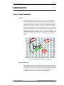
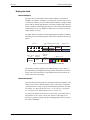
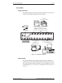


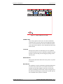
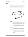


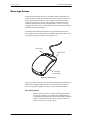


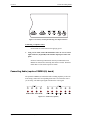
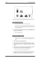
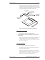


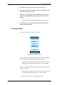

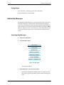


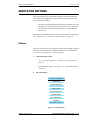

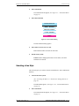
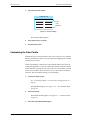

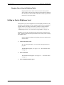
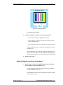


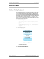
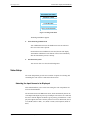
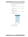
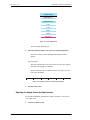
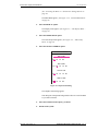
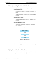
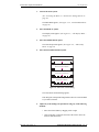
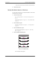


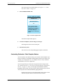


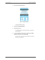


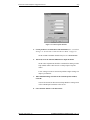


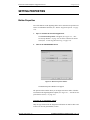
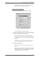
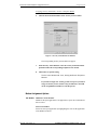


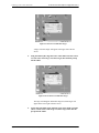


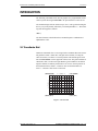


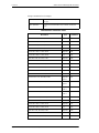


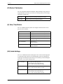
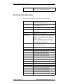
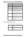


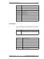
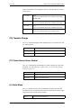
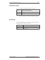


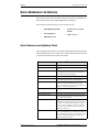


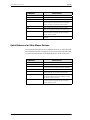


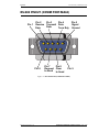


![UB25 Cover+Front Matter [Rev C] -- 1-02](http://vs1.manualzilla.com/store/data/005906297_1-9ba350e3ad2195c1d2103c91c2552cc1-150x150.png)