1
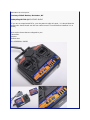
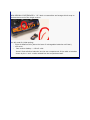
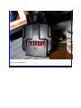
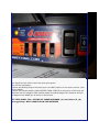
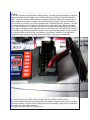
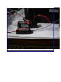
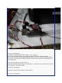
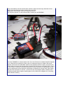
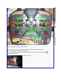
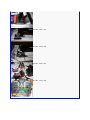
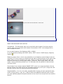
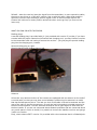
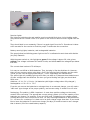
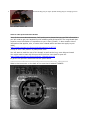
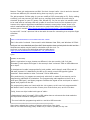
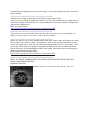
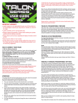
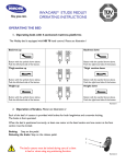
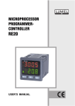
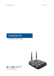
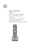
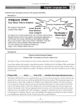
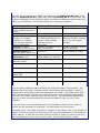
The radio recommendations by WRMYC include three- the Hobby King HK T4A 2.4 gHz radio, the Spektrum DX-5e 2.4 gHz radio, and the Spektrum DX 6i 2.4 gHz radio. Any of these is adequate for the Soling One Meter, but there are differences as you step up to radios w/ more features. See the chart below for a summary of features. Hobby King HK T4A Price w/ receiver: $ 25 + shipping (as much as $40) Availability: internet only Batteries: 6 X AA, non included, no recharge allowances, no charger, must recharge separate from the transmitter Receiver: included, compatible w/ this TX only. Voltage indicator: tricolor LED green-yellow-red Exponential rates adjustment: none Servo reversing: slide switches on face Model memory: One Spektrum DX 5e Typical: $ 99 Spektrum DX 6i Typical: $ 199 Any hobby shop or internet 4 X AA, batteries included, no recharge allowances, no charger, must recharge separate from the transmitter included, compatible w/ any DSM 2 transmitter Four LED’s Any hobby shop or internet 4 X AA, rechargeable batteries included, recharge port in TX, wall charger included. 2 Preset exponentialsallows rudder “LO” and “HI” slide switches on face Unlimited adjustment One Ten Channels: 4 5 6 Packaging: plastic bag w/ bubble pack User manual: None Molded Foam/ Box Molded Foam/ Box Yes Yes Service: None Ship to IL Ship to IL included, compatible w/ any DSM 2 transmitter Digital readout of voltage programmable There are many additional radios available; we recommend ONLY 2.4 gHz radios. The Spektrum DX 6i and other “computer radios” have features that are useful in terms of “exponentials”- being able to have dual settings for the rudder. The rudder at the High setting will almost spin the boat in its length; that is too much adjustment and leads to over use of the rudder, and slowing on the race course. The exponentials adjustments allow you to have a second setting that moves the rudder far less, for use in most situations. As you buy even more sophisticated radios, you get features that are more suited to aircraft, and not necessary on a sailboat. You also spend a lot more money. Evaluating value: The Hobby King radio is a bargain in any league. But, it has virtually no support- not even a manual (nor one online). But, once you understand it, you should not need a manual. It does not come with a box for storage or resale (or return for service)again something you may or may not ever need. So, the Hobby King IS a viable alternative at a low price. Courtesy of Walt Bankes, Rochester, NY Hobby King HK T4A QUICK START GUIDE [If you are an experienced RCer, you may want to skip this post - it is aimed that the newbie who should check out the new radio to see if it works before installing it in a model] Here are the items that are shipped to you: Transmitter Receiver Binding plug OLD VERSION 1 RADIO NEW VERSION 2 DIFFERENCES > "v2" label on transmitter and orange shrink wrap on dipole antenna end of the single receiver You will need for initial testing: - Eight AA Alkaline Cells (leave the issue of rechargeable batteries until later) - one servo. One receiver battery – 4.8 to 6 volts Insert 8 fresh alkaline batteries into the rear compartment of the radio oriented as shown by the + and - marks molded into the compartment wall. Turn on the Transmitter. You should see the LED on the front panel glow green. Turn off the transmitter. Connect the Binding Plug to the three pins in the BAT position on the main receiver. (See picture below) Connect the receiver battery (NO GREATER THAN 6 VOLTS) to any other of the three pin positions with the negative side (usually black) toward the edge of the Receiver and the +voltage to the middle pin as shown in the picture. GET THIS RIGHT, TOO - EITHER OF THESE MISTAKES -(a) more than 6 V, (b) wrong polarity- WILL SURELY BLOW THE RECEIVER SIDEBAR: [If you do not have an appropriate voltage battery, you have probably bought a model kit that provides the correct voltage to the receiver through an Electronic Speed Controller (ESC) - the ESC contains a BEC (battery eliminator circuit) to reduce the voltage from a higher voltage to the proper voltage. You should borrow a proper , less than 6v. battery from a friend. If you don't, you are presented with a "chicken and egg" problem - you will be simultaneously trying to setup and test both your model and your radio at the same time - that is difficult for a newbie since there are possible conflicting issues with setting up the radio and setting up the ESC and motor for the first time - GET HELP]. Of course, if you already have a working model for which you are just changing radios, all you need to do is plug the ESC into the Rx for your testing - no problem. However, you might be a complete newbie with this new radio and a new model - then you will need help. ************************************************** ** You should now see an LED on both the main and the satellite receivers blink. They are sometimes hard to see because they are hidden inside the case, which is a dark, translucent plastic. It is kind of like looking at someone smoking a cigar who is inside of a SUV which has dark tinted windows. These pictures should help you locate them. Pick up your transmitter, hold down the "BIND RANGE TEST" button - don't release it, Turn on the transmitter power while watching both LEDs blink on the receivers. When the two receiver LEDs stop blinking and stay lit you may release the BIND button. The receiver is now bound to YOUR transmitter and will only respond to commands from THAT transmitter. Disconnect the battery from the receiver unplug the binding plug and put it in a safe place - you will not use it often (if ever). But if you do need it - you need it NOW. Turn off the Transmitter. Plug a servo into the CH1 location on the receiver. Turn on your transmitter. Plug in the battery into the receiver BAT position- again with the neg. lead next to the edge of the case and the positive lead in the center pin. Always do it in this order - turn on Tx then turn on Rx. The only time you do it in the reverse order is when you are BINDING. This image has been resized. Click this bar to view the full image. The original image is sized 1024x768 and weights 90KB. Move the CHANNEL #1 control stick on the Tx to see if the servo rotates about 90 degrees or so. Move the trim control for CH1 to see if it causes the servo to rotate a few more degrees. Move the CH1 "REV-NOR" switch to the opposite position. Again, move the CH1 control stick to ensure that the direction of rotation of the servo is reversed. [Note: This is for the "Mode 2" version. If you have the Mode 1 version (throttle on right stick) you will have to experiment to find what the relationship is between the control stick, REV switch, and the CH#? connector on the Rx - some of us who use multiple radios, find this issue confusing enough that we place masking tape on the radio with a diagram on it showing which control is which] Control layout for "Mode 2" transmitter Now, move the servo to the next connector and repeat the above tests. All four channels should behave the same. If so, congratulations! You will not have to send the radio back to be replaced Attached Thumbnails 89.0 KB · Views: 327 61.4 KB · Views: 222 58.0 KB · Views: 213 56.9 KB · Views: 236 89.8 KB · Views: 273 62.5 KB · Views: 242 Picture From HK site - short antennas 55.4 KB · Views: 363 My four Rx look like this 58.8 KB · Views: 356 WHAT THIS RADIO SET WILL NOT DO. Compatibility - The transmitter may not be used with other brands of receivers and the receiver may not be used with other brands of transmitters. EDIT: see message 195 for some exceptions to this. It is not dual frequency (like Spektrum DSM or DSM2). V1 is not frequency hopping (like FASST radios). EDIT: Version 2 DOES employ frequency hopping Distance (range) of use - since it only transmits on one frequency (even though it has two receivers) it is not as immune to interference and path of signal problems as the high priced radios. And it is not as powerful as the other radios. For those two reasons this radio set should be used only for limited range models - parkflyers, indoor flight, boats, cars, and robots. I have controlled a sailboat over 700 feet away with the satellite Rx disconnected (see post #109) Even though it has a button labeled "RANGE TEST", there is no range test feature. On the earliest versions you could remove the transmitter antenna to, sort of, do a range test. But the later versions have the antenna permanently fastened. Programmability - it is not, in any way, programmable. It does not have exponential rates, control mixing (elevon, v-tail, etc.). And for setting the NOR/REV setting for each control, you must manually adjust front panel switches as you move from using it with one model to another. Failsafe - when the receiver loses the signal from the transmitter, in more expensive radios, the servos are driven to a "fail safe" position. Not so with this radio. When that condition exists the receiver stops sending a position signal to the all servos except channel #4. Channel #4 is driven to center position and all the other servos go limp (no force on the lever arm). WHAT YOU CAN DO WITH THIS RADIO Binding plugs: A second binding plug is provided with V1 (not provided with version 2) so that, if you have a model with the proper external on/off switch and charging port, you may bind the receiver to the transmitter with out having to access the receiver - you just plug the special binding plug into the charging port, instead. Normal binding plug on right. Special charging port binding plug on left. Antenna: All but the vary earliest versions of the receiver are equipped with an antenna on the end of a coaxial cable, so that you may have more latitude in positioning the antenna in a model that has limited space to do so. The last one inch of the cable is the active antenna and the rest of the cable is just for convenience. So only the last inch needs to oriented properly for the best communication. The two antennas should be set at right angles to each other for the best results. If you are not concerned about distance problems and are concerned about very small space in which to install, it is possible to remove the satellite receiver and just go it with one receiver. Early, short antenna EDIT: version 2 is provided with a short antenna that is a folded dipole. Early antenna: Later, long antenna Receiver lights: The lights on both the main and satellite receivers should blink when in the binding mode. They should be off if either: there is no power or the receiver does not find a signal from the Tx. They should both be on constantly if there is a good signal from the Tx. Sometimes it takes a few seconds for the receiver to find the proper Tx and make the connection. Battery warning lights, batteries, and rechargeable batteries: The green/yellow/red-blinking power light on the Tx is calibrated to work best with alkaline (dry cell) batteries. With the power switch on, the light glows green if the voltage is above 9.8 volts, glows yellow if the voltage is between 9.8 and 8.8 volts, and blinks red if the voltage drops below 8.8 volts. The current draw is about 175 milliamps. It is easy to use NiCad or NiMH batteries. They just plug in like the alkalines do. However, there are two concerns when using them. One is the warning light indication and the other is that you will need an appropriate charger - it isn't supplied by the manufacturer. The yellow light will probably light up soon after you start to fly because these batteries are of lower voltage than the alkalines. So when you get a blinking red light you should land REAL soon. Alkalines = 6 X 1.5 V = 9 V min. (all batteries yield higher voltage when fully charged.) Rechargables = 6 X 1.2 V = 7.2 V If you do not remove the batteries to recharge them in an external charger, you will need a "wall wart" type charger of the proper polarity, and current rating. It needs to be 12 volts. Recharging: The polarity is REAL important - it must have positive voltage on the center contact of the connecter. The appropriate current rating is about 1/10 of the capacity of the batteries you choose. For example, if you use 2000 mah TX batteries your charger should provide about 200 ma of current at 12 volts. For fully discharged batteries it will take about 10 - 15 hours for a recharge. It is best not to let them charge longer than that. If you would like to leave the batteries on continuous charge (for days) it would be best to use a charger that is about 1/20 of the rated battery capacity. Normal binding plug on right. Special binding plug for charging port on left. 66.2 KB · Views: 175 Guide to other posts and other threads Now, for the more adventuresome, I will point you to places that you can find information you will need to get your hands dirty with soldering and all that stuff. The long thread that contains most information of importance to you is here [Careful - it also contains lots of information that applies, also, to some other related radios and does not apply to your radio] http://www.rcgroups.com/forums/showthread.php?t=967207 It's up to over 1300 posts in a pretty short time! You will want to read the rest of this thread, as well as the long, more diverse thread. You might want to start with this post #19 and then come back to post #5. http://www.rcgroups.com/forums/showp...8&postcount=19 to get all the questions answered that are posed below ************************************************** *********** What is that connector on the back of the case that is labeled TRAINER. Beware: These pin assignments are ONLY for the 4 channel radio - the six and nine channel versions are different pin outs and mixing them up may fry your radio. The jack accepts a S-Video plug (or you can modify a PS/2 mouse plug to fit). So by making a cable(s) you may connect you radio up to a computer and practice at home using a simulator program on your PC (posts # 84, 86,and 87). Or you can wire it to another radio to be used with an instructor that will be able to hand over control of his airplane to you however this requires significant modification because, among other issues, there is no switch installed that will allow the instructor to grab control away from the student if the student gets in trouble. http://www.rcgroups.com/forums/showt...2#post12898172 In post #105 "crucial" reports a link to the cable he uses for connecting to a computer flight simulator: Quote: https://www.dealextreme.com/details.dx/sku.11996 That is the cable I ordered. I have used it with Windows Vista 32bit, and Windows XP 32bit. And here is a more detailed post from MoFl that explains how and why both the HK and the DealExtreem cables may be used for simulation with the 4 ch. Tx. And here is the link to the HobbyKing cable he talks about: https://www.unitedhobbies.com/UNITED...for_Win2000/XP Quote: @calle3 & JohnsPop wjbite is right when he says pinouts are different in the two models (4 & 6 ch) but, fortunately, both output PPM signal in the same pin that "universal" PPM to USB cables use as an input. So, dealextreme's cable is appropriate for both models, and it doesn't need PPJoy and all that stuff, because it is detected by the OS as if it was a normal USB joystick (game controller). Same applies to other "universal" PPM to USB cables. PPJoy and the mis_b's program are used only with the 6 ch model if you want to use it's programming cable also for simulation. The programming cable appears to the PC as a serial port (COM port), and these programs interface the signal at the serial port to make it appear as a joystick to the OS. The programming cable won't work with the 4 ch system, as this one isn't programmable and doesn't have a serial port at the 2 lower pins of the trainer port, as the 6 ch does. Finally, there are chips inside both types of cable: * Dealextreme's and "universal" PPM to USB cables have a microcontroller that reads the PPM input and simulate a USB game controller. * The one inside the programming cable is a serial to USB converter ********************************************** Some have reduced the number of battery cells to four from eight. After all this new technology really needs only 5 volts to operate, so why not. It seems like the redesign for the new technology, in this case, ignored the lack of need for higher voltage. ********************************************* Modifying the voltage thresholds for the battery charge status LEDs: Since you may be using rechargeable batteries (or even just 4 batteries) you might want to modify the voltage thresholds for your chosen batteries to cause the lights to indicate more appropriate voltage levels . Start your search here: http://www.rcgroups.com/forums/showp...&postcount=989 ********************************************* If you want to move the throttle stick from the left to the right or vice versa (Mode 2 to Mode 1) you can learn to do it here. Look at post #19 again. ********************************************* Maybe you have a one or two thousand dollar radio that "walks, talks, and crawls on it belly like a reptile" but is NOT 2.4 GHz - don't despair - here is lots of great information on how to buy this cheap radio - take the 2.4 GHz transmitting module out of it - and install it into your super radio. Uses the expensive computerised features of your old radio and allows you to have the 2.4 GHz advantage of MUCH less hassle with interference and having your radio impounded at the flying field. Idiot's guide to hacking these radios: http://www.rcgroups.com/forums/showp...&postcount=865 ********************************************** NOTE: ALL POSTS, THROUGH POST #63, BELOW WERE WRITTEN BEFORE THE FOUR POSTS, ABOVE WERE WRITTEN. Attached Thumbnails TRAINER connector on the 4 channel radio 46.5 KB · Views: 211