1
Functional System Safety – Simulator Environment
Master of Science Thesis at Computer Science and Engineering
PETTER GUSTAVSSON
HENRIK ROSLUND
Department of Computer Science and Engineering
CHALMERS UNIVERSITY OF TECHNOLOGY
UNIVERSITY OF GOTHENBURG
Göteborg, Sweden, July 2010
The Author grants to Chalmers University of Technology and University of Gothenburg the non-exclusive
right to publish the Work electronically and in a non-commercial purpose make it accessible on the Internet.
The Author warrants that he/she is the author to the Work, and warrants that the Work does not contain text,
pictures or other material that violates copyright law.
The Author shall, when transferring the rights of the Work to a third party (for example a publisher or a
company), acknowledge the third party about this agreement. If the Author has signed a copyright agreement
with a third party regarding the Work, the Author warrants hereby that he/she has obtained any necessary
permission from this third party to let Chalmers University of Technology and University of Gothenburg
store the Work electronically and make it accessible on the Internet.
PETTER GUSTAVSSON
HENRIK ROSLUND
© Petter Gustavsson, June 2010.
© Henrik Roslund, June 2010.
Examiner: Sven-Arne Andreasson
Chalmers University of Technology
University of Gothenburg
Department of Computer Science and Engineering
SE-412 96 Göteborg
Sweden
Telephone + 46 (0)31-772 1000
Abstract
In recent years strictly mechanical solutions have evolved towards electromechanical which have introduced
an increase in complexity that cannot be ignored. This is especially important for safety critical systems and
the way they are developed. This thesis is part of a project with the goal of evaluating the development
process ISO26262 concerning safety critical systems in vehicles. The result of this thesis is a multi-interfaced
presentation system for demonstrating the effects of not correctly handling hazards in a Steer-by-Wire system.
The presentation system is written in C/C++ programming languages and connects different interfaces such
as; Vehicle Simulator, CAN communication, HUD presentation, Microcontroller and Steering controls.
Glossary
The following chapter provides explanations of abbreviations, central terms and expressions that are used
throughout the report.
Term
Description
AI
Artificial Intelligence - Intelligence of a machine or software.
API
Application Programming Interface - A software implemented interface that enables
it to interact with other software.
Betula
A programming suite for Bluetooth development in the automotive industry.
Bug (software)
An error, flaw, failure caused in a computer program that causes unexpected
behavior.
Collision detection
Algorithms used to check collision, i.e. intersection, between objects.
DDK
Driver Development Kit.
Demo (game)
A free demonstration or preview of a computer or video game.
ECU
Electronic Control Unit
GUI
Allow users to receive data from and interact with machines, computers etc. through
a graphical component.
HMI
Human-Machine Interface - An HMI is often used as a visualization of data that
users sometimes can interact with.
HUD
Head-up display - Visual representation of information in computer and video
games.
Infotainment
Information-based media content.
IOCTL
Group of operations used for low level communication with IO-devices.
Joystick
In this report, joystick refers to a collection of the different parts of a game
controller.
Multiplayer (game)
A gaming mode for multiple players on the same server.
Open source
Practice in production and development that promote access to the software source
code.
OutGauge
An output interface provided by Live for Speed to receive gauge data.
Polygon
Used in computer graphics to create objects and surfaces.
PPJoy
Parallel Port Joystick – Virtual joystick driver, [1].
Process (software)
An instance of a computer program that is executed.
PWM
Pulse-Width Modulation – A way of defining varying pulse lengths.
RGB
Red Green Blue.
SDK
Software Development Kit - A set of development tools that allows for creation of
applications to hardware platforms, computer systems etc.
Texture
Image applied to the surface of a polygon or shape in computer graphics.
Thread (software)
Used within software to run concurrent tasks.
Transducer
Converts energy from one unit to another.
Table of Contents
1
2
Introduction ................................................................................................................ 1
1.1
Background ................................................................................................................................. 1
1.2
Purpose........................................................................................................................................ 1
1.3
Objective ..................................................................................................................................... 1
1.4
System Overview ......................................................................................................................... 2
1.5
Simulator ..................................................................................................................................... 3
1.6
Communication Interfaces ........................................................................................................... 3
1.7
Steer-by-Wire System .................................................................................................................. 4
1.8
Scope .......................................................................................................................................... 4
Technical Background ................................................................................................ 5
2.1
2.1.1
Real-time OS and General-purpose OS .................................................................................... 5
2.1.2
Linux ...................................................................................................................................... 5
2.1.3
Windows ................................................................................................................................. 5
2.2
Windows API .............................................................................................................................. 6
2.2.1
Component Object Model ........................................................................................................ 6
2.2.2
Distributed COM ..................................................................................................................... 7
2.2.3
DirectInput .............................................................................................................................. 7
2.3
2.3.1
3
Operating Systems ....................................................................................................................... 5
Force Feedback ............................................................................................................................ 8
Effects ..................................................................................................................................... 8
2.4
Virtual Joystick .......................................................................................................................... 10
2.5
The Populus Editor .................................................................................................................... 10
2.6
Steer-by-Wire ............................................................................................................................ 11
2.7
Controller Area Network ............................................................................................................ 11
2.8
Simulator ................................................................................................................................... 12
Hardware .................................................................................................................. 13
3.1
Potentiometer Sensor ................................................................................................................. 13
3.2
Analog-to-Digital Converter (A/D)............................................................................................. 13
3.3
Dell Alienware Laptop ............................................................................................................... 14
3.4
USB Interface Board .................................................................................................................. 14
3.5
Freescale i.MX515..................................................................................................................... 14
3.6
Sharp Display LQ123K1LG03 ................................................................................................... 15
3.7
BASIC Stamp ............................................................................................................................ 15
4
3.8
Mecel USBtoCAN Adapter ........................................................................................................ 16
3.9
Kvaser Leaf Professional ........................................................................................................... 16
3.10
The Steering Prototype ............................................................................................................... 16
3.11
Logitech G25 Racing Wheel ...................................................................................................... 17
Methodology............................................................................................................. 18
4.1
4.1.1
Project Application ................................................................................................................ 18
4.1.2
Simulator............................................................................................................................... 19
4.1.3
HMI ...................................................................................................................................... 20
4.1.4
Steering Wheel ...................................................................................................................... 20
4.1.5
CAN...................................................................................................................................... 21
4.1.6
Wheel Sensor and Velleman USB Interface Board ................................................................. 21
4.2
Design ....................................................................................................................................... 21
4.2.1
Basic Design ......................................................................................................................... 21
4.2.2
Design of Application GUI .................................................................................................... 22
4.2.3
Designing HMI Interface ....................................................................................................... 23
4.2.4
Data Flow.............................................................................................................................. 23
4.2.5
Steering Wheel Software Design ............................................................................................ 24
4.3
Implementation .......................................................................................................................... 25
4.3.1
Application Implementation ................................................................................................... 25
4.3.2
Building the HMI .................................................................................................................. 26
4.3.3
Concurrency and Threads ...................................................................................................... 26
4.4
4.4.1
5
Analysis .................................................................................................................................... 18
Testing ...................................................................................................................................... 26
Test System ........................................................................................................................... 26
Simulator Evaluation ................................................................................................ 28
5.1
Requirements............................................................................................................................. 28
5.2
Pre-study ................................................................................................................................... 28
5.3
Evaluation Criteria ..................................................................................................................... 29
5.3.1
Visual Quality ....................................................................................................................... 29
5.3.2
Gameplay .............................................................................................................................. 29
5.3.3
Customization ....................................................................................................................... 29
5.3.4
Interface support .................................................................................................................... 30
5.3.5
Other Criteria ........................................................................................................................ 30
5.4
Chosen Simulators ..................................................................................................................... 30
6
Result ....................................................................................................................... 32
6.1
6.1.1
System Overview ....................................................................................................................... 32
GUI – Release Version .......................................................................................................... 33
6.2
Simulator ................................................................................................................................... 33
6.3
Steering Wheel .......................................................................................................................... 34
6.3.1
Key Functions ....................................................................................................................... 34
6.3.2
Force feedback Align Effect................................................................................................... 35
6.3.3
Force Feedback Dampening Effect ......................................................................................... 35
6.4
HMI .......................................................................................................................................... 35
6.5
CAN .......................................................................................................................................... 36
6.6
Sensor ....................................................................................................................................... 36
6.7
Virtual Joystick .......................................................................................................................... 36
6.8
Application Flow ....................................................................................................................... 37
6.9
Test System ............................................................................................................................... 39
6.9.1
6.10
Steery Model ......................................................................................................................... 40
GUI – Debug Version ................................................................................................................ 40
7
Discussion ................................................................................................................ 42
8
Future work .............................................................................................................. 44
9
Bibliography ............................................................................................................. 45
Appendix A ..................................................................................................................... 47
Appendix B ...................................................................................................................... 47
Appendix C ...................................................................................................................... 49
Appendix D ..................................................................................................................... 49
1
Introduction
The following chapter briefly introduces the thesis background, purpose and objective.
1.1
Background
Today, the use of software and electronics in vehicles escalate exponentially. Legally mechanical solutions
are replaced with electromechanical variants and the increased complexity that arises must be handled
successfully in order to produce safe vehicles to competitive prices.
This thesis is part of a project aimed at implementing a Steer-by-Wire system mainly motivated by an
opportunity to evaluate the life-cycle procedures of the ISO26262 standard. This is a standard for how to
handle and secure safety implementation of complex electrical systems in vehicles. The complete prototype
should be divided into one safety-critical Steer-by-Wire part and a simulator system that should be used to
control the safety-critical part.
1.2
Purpose
This thesis is aimed at developing a simulator system which will be used to demonstrate how a correctly
implemented Steer-by-Wire system, that uses ISO26262, handles hazards and errors that occur and the effects
of not doing so.
1.3
Objective
The simulator system will include both software and hardware components. The hardware consists of a
steering wheel with force feedback capabilities, a PC, a display and different interfaces that will be used to
connect the independent Steer-by-Wire system. The simulator will simulate a road and provide the user with a
realistic experience of driving a car, provide the Steer-by-Wire system with data about steering angle and
retrieve actual steering angle of the wheels from the Steer-by-Wire system. This data is fed into the simulator
and also used to create any required force feedback in the steering wheel. The user will also be presented with
necessary driver information derived from user input, simulator state and Steer-by-Wire data.
An important part of the simulator is to receive and present synchronized information in real-time. Before the
actual Steer-by-Wire system is developed, the PC shall be able to use a simplified model of the system for
testing.
1
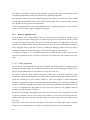
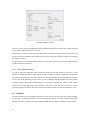
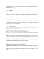
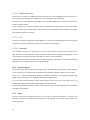
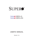
Fig. 1 A high-level overview of the system.
1.4
System Overview
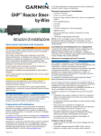
The system consists of three separate interacting parts as marked in fig 1. This thesis focuses on the simulator
part. There are four different sources of communication that interact with the simulator as either input or
output. The steering wheel will provide steering-angle data that will be passed on and translated by the Steerby-Wire system as applicable data through Universal Serial Bus (USB) communication. The Steer-by-Wire
system will use the data received and translate it into a steering-angle and return a wheel-axis position that
will be used to control the simulator and the force feedback of the steering wheel for user feedback. Finally
there is a communication to a Human-Machine Interface (HMI), which will provide visual guidance to the
user representing system state and simulation data.
Fig. 1 also specifies a controller part which will interact with the Steer-by-Wire system by introducing
hazards. These hazards can be used to demonstrate how the system reacts in safety critical situations.
2
1.5
Simulator
One of the main features in the project is the simulator providing the visual feedback to the user from the
Steer-by-Wire system. The simulator will be a realistic representation of a driving environment with the user
in the driver’s seat. Because the Steer-by-Wire will act as a model of a system used in real cars, the simulator
will have to act as realistic as possible to give good feedback of how well the Steer-by-Wire reacts to realistic
situations.
The project includes finding a suitable simulator and customizing it to fit the requirements of the system.
Therefore the simulator chosen must be able to support these requirements from the system. There is also a
possibility that no simulator can support all the requirements and therefore the best fit must be found.
1.6
Communication Interfaces
All the devices connected to the simulation platform will preliminarily interact through USB communication
as marked in Fig. 1. USB is the universal communication interface for computers, but seldom used on circuit
boards where other standards are specified and signals will therefore have to be converted to work correctly.
The conversion can require some extra operating drivers to work which have to be developed.
The interface connected between the steering wheel and the simulation platform will use standard USB
communication with operating drivers provided by the hardware vendor. The project requires the simulation
platform to both read and write data to the steering wheel. When the user performs a steering movement the
new angle should be read and redirected to the Steer-by-Wire system. And if the steering wheel and Steer-byWire system are out of sync, the force feedback provided in the steering wheel should be used to force them
in sync. Understanding how to program the steering wheel require documentation and a Software
Development Kit (SDK).
The simulation and Steer-by-Wire platform will have communication between two different interfaces
providing input and output from the simulation engine. The output will provide steering angle to the Steer-byWire system and the input will provide the steering angle to the simulator and create force feedback on the
steering wheel.
The simulation platform will also be connected to an HMI system through USB communication that will
show detailed visual data from the simulation.
Because the system will run in real-time, the communication between the different systems must produce
close to no latency between input and output to the simulator. This requires both a well-defined model for the
communication, as well as research of how this model can be optimized. This is a part that needs early
consideration in the project.
3
1.7
Steer-by-Wire System
The simulator and its interfaces towards the Steer-by-Wire system need to be tested in some capacity. The
Steer-by-Wire system is under development and can therefore not be used for testing thus; other solutions for
testing must be considered. This might be some form of diagnostic tool; however, if time allows it might be
possible to bypass the Steer-by-Wire core and connect directly to the wheel axis using some simplified
steering model.
1.8
Scope
This thesis does not include any parts of development of the safety critical Steer-by-Wire system “Steery” or
the controller part “Conny” as shown in Fig. 1. The simulator is not required to enforce the ISO26262
development process.
4
2
Technical Background
The following chapter explains the theoretical foundation that the result is based on, and is important for a
greater understanding of the systems.
2.1
Operating Systems
Developing a system based on both high-level (application) and low-level (CAN/USB) systems require a
suitable platform to build upon, that can provide a good compromise between both these system levels. There
are mainly two operating systems (OS) available to be used in this project based on their listed features;
Windows and Linux.
2.1.1
Real-time OS and General-purpose OS
Operating systems are often split into two theoretical categories; real-time operating systems (RTOS) and
general-purpose operating systems (GPOS). RTOS is mainly used when fixed deadlines i.e. timing is critical.
The name is based on the fact that RTOS has close to none delay in serving application request, and offer
programmers more control over process priorities; an application process priority might even exceed the
system process priority in such systems, [2].
General Purpose OS allow many processes to execute at the same time through the OS scheduler. This
scheduler can be given priorities as well, but never above system processes and will try to handle all requests
without consideration to timing.
2.1.2
Linux
The UNIX-based operating system Linux is highly popular due to its open source structure, which allows the
community to share and create new distributions from one core system. This makes Linux a very flexible OS
that allows for both GPOS and RTOS distributions. In difference to e.g. Windows, Linux allow for full
control to be customized and reengineered by the user, [2].
Because of the open source structure and underground label, Linux hasn’t got the same level of compatibility
as Windows by 3rd part software, but due to a large community the solutions are distributed rapidly between
users, [3].
2.1.3
Windows
Windows is the currently biggest OS on the market created by Microsoft™ with its history starting in the late
seventies when Microsoft was developing a graphical interface that was later renamed Windows, [4]. The
name Windows refers to the metaphor of the operating system visualizing its Graphical User Interface (GUI)
by using a desktop that contains different windows for user interaction. The big success of Windows has
5
created a huge 3rd party industry with high level of documentation and solution descriptions; most hardware
and software is supported in Windows.
The main advantages of using Windows are the compatibility aspect of both hardware and software; most
software is created with Windows as main platform, [3]. Still the OS is closed source and require the user to
work with an Application Programming Interface (API) created by Microsoft, and the OS is not considered to
be a RTOS.
2.2
Windows API
The Windows API (WinAPI) is the main collection of APIs for the Windows system. Most applications used
within the Windows environment use WinAPI for communication purposes. There is a large set of different
wrappers, services and libraries within the WinAPI that covers many areas, but can also be deprecated, backcompatibility-only, APIs from legacy systems.
For multimedia purpose the DirectX API is the most commonly used interface and has been a part of the
Windows system since the release of Windows 95 (1995). DirectX contains different sub-APIs used to access
different sets of hardware. The main usage of DirectX is the Direct3d API for 3d graphics, DirectDraw for 2d
graphic rendering, DirectSound for hardware sound buffering and DirectInput for communication with input
devices such as joysticks, gamepads and PC steering wheels.
Program interaction is mainly maintained via the Component Object Model (COM) architecture or the more
newly created and highly popular .NET Framework.
2.2.1
Component Object Model
The COM architecture was created by Microsoft and introduced in 1993 as a multi-tier strategy for
applications to communicate through. This basically means that COM allows application to communicate in a
server-client fashion through binary components with defined interfaces.
Earliery source code dependency was the usual programming style where all source code had to be available
to compile the application binary which, because of all the dependencies, caused difficulty to organize team
efforts and compile-time problems. Therefore the COM architecture is structured as a component based
system where every component is binaries with interfaces and can be reused without source code
dependencies or updated individually.
The main architectural style of COM is based on object-oriented programming (OOP) and is meant for clients
to communicate with objects. Using the OOP style allows for a higher degree of reuse and maintainability.
It’s also possible to create language-independent objects that only require communication to the interface, not
via specialized syntax.
One of the most important architectural decisions in designing COM was for Microsoft to separate
implementation from interface i.e. design COM on the idea of interface-based programming (IFP). The
6
interface of the object defines a set of public methods, much like classes, but does not include any
implementation. This will create a specific protocol for communication between clients and objects, [5].
2.2.2
Distributed COM
One of the most important adaptions of COM was the further development of distributed COM. When
introduced, COM could only communicate when the server and client process was running on the same
computer. This was a drawback due to the main concept of COM was to transcend process boundaries. By
introducing a new wire protocol, in relation to the Windows NT 4 release, support for inter-process
communication between computers was added to COM.
COM’s support for distributed application is based on an inter-process mechanism called Remote Procedure
Call (RPC) which is an often used industry standard and has a long history. To support COM, Microsoft
developed an enhanced version of RPC called Object RPC (ORPC) which added object-oriented extensions to
accommodate the COM architecture, which was based on OOP whilst RPC was not.
The relation between COM and RPC in ORPC is important and interconnected in the sense that COM offers
RPC an object-oriented feel and RPC offers COM to serve a communication interface over networks. The
result of this interconnection is a system that can serve application communication to distant computers and
hide low-level details to act as if the communication was done within the same system, [5].
2.2.3
DirectInput
DirectInput is a part of the Microsoft DirectX API and enables applications to receive and process device
input. It is not recommended for simple mouse or keyboard input since its usage mainly concerns game
controllers and applications with demands on real-time response such as simulators. DirectInput also enables
the use of force feedback devices.
In order to obtain access to a device, DirectInput uses a layered model. At the top most level is the
IDirectInput8 interface, followed by the IDirectInputDevice8 interface where the number 8 refers to the
interface version. The IDirectInput8 interfaces allows for enumeration of available devices and retrieval of the
wanted device’s interface via instantiation of an IDirectInputDevice8 object. Each device, e.g. a joystick, that
is to be accessed will have to be instantiated as an IDirectInputDevice8 object. Furthermore each such object
can contain several device objects representing buttons and axes however these are encapsulated in a
structure.
DirectInput allow applications to run in the background and still retrieve device data and enables several
applications to access the same device. With the exception of force feedback devices which must be
exclusively acquired if the force feedback is to be used. Note however that even though one application has
acquired exclusive rights, several applications can still receive input from a force feedback device as long as it
is acquired in non-exclusive mode, [6].
7
2.3
Force Feedback
Force feedback is a widely used concept that adds another dimension to user feedback possible in simulators.
This is especially favorable when the aim is to provide a realistic user environment. It has been used in
computer games for several years and recently the use of sophisticated simulators in educational purposes has
become more common. Examples of this are surgery simulators for medical students and driving simulators
for educating first-time drivers before actually using a real vehicle, [7]. Both these applications can potentially
decrease mistakes and accidents in the real world. Using force feedback in devices associated with such
simulators is a common addition to achieve a realistic feeling for the user.
Force feedback in gaming steering wheels can be accessed via DirectX library DirectInput [8], described in
section 2.2.3. Devices usually support a set of predefined feedback effects such as a Constant Force in any
direction or a Conditional effect which allows for use of device sensor data e.g. offset, speed, and acceleration
(must be supported by the device).
Using fairly complex effects can be necessary to achieve realistic user feedback e.g. when a car enters a
section of mud the driver should experience a heavier steering. This can be modeled in a simulation by
introducing dynamic inertia to the steering wheel. Depending on the realism of the simulation there might be
several effects affecting the steering wheel simultaneously.
Depending on the device being used, it is possible to load effects into it and then simply triggering it when
necessary.
2.3.1
Effects
This section provides the user with a general understanding of different types of effects. The effects described
here belong to the category of Conditional effects, since they require sensor data to calculate the amount of
force that should be applied.
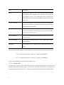
2.3.1.1 Spring Effect
A Spring effect is used to create forces pointing towards a defined center, [9]. The center is defined as an
offset from the joystick’s actual center position. The effect uses data from the position sensor to provide a
dynamic force depending on the distance from the offset. There are six key parameters that affect the amount
of force being exerted:
8
Term
Description
Offset
Ranging from -10.000 (full left) to 10.000 (full right) which defines the
center around which the dynamic force is calculated. As an example if
one would like to create a force centering the joystick at 90 degrees the
offset should be set at 5.000, assuming that the joystick provides a 360
degrees axis.
Positive Coefficient
Used to affect the amount of force produced towards the offset when the
position sensor indicates a current position away from the defined offset
along the positive axis direction.
Negative Coefficient
Used to affect the amount of force produced towards the offset when the
position sensor indicates a current position away from the defined offset
along the negative axis direction.
Positive Saturation
Used to define the maximum amount of force available for the positive
side of the offset.
Negative Saturation
Used to define the maximum amount of force available for the negative
side of the offset.
Dead Band
Used to define an area around the offset at which the effect does not
apply.
The amount of force that should be exerted is dynamically calculated according to the following formulas:
))
))
The Position is determined using the joystick’s internal sensors.
2.3.1.2 Damper Effect
A Damper effect is used to create an effect which exerts forces counteracting joystick movement. The force is
dynamically calculated using the joystick’s velocity sensors. The effect uses the same six key parameters as
the spring effect described in section 2.3.1.1, however, the parameters are interpreted in a different context.
9
Term
Description
Offset
Ranging from -10.000 (full left) to 10.000 (full right) and defines a position
along the joystick axis which is mainly used in collaboration with the Dead
Band parameter.
Positive/Negative
Used to affect the amount of force produced to counteract movement.
Coefficient
Positive Saturation
Used to define the maximum amount of force available for the positive side
from the offset.
Negative Saturation
Used to define the maximum amount of force available for the negative side
from the offset.
Dead Band
Used to define an area around the offset at which the effect does not apply.
The amount of force that should be exerted is dynamically calculated according to the following formulas:
))
))
The Velocity is determined using the joystick’s internal sensors.
2.4
Virtual Joystick
A virtual joystick provides functionality to manipulate a joystick’s state without using any actual hardware. A
major advantage of using a virtual joystick detectable by the operating system is that it can be used like any
other non-virtual joystick for applications. That is, it does not require any modification of existing
applications to successfully integrate. The state of a virtual joystick can be controlled via IOCTL calls in the
operating system. A virtual joystick can contain the same parameters as a real joystick.
2.5
The Populus Editor
The Populus suite is a collection of Mecel products and allows for creating advanced HMIs in a very efficient
way, [9]. The focus is on designing, implementing and verifying HMIs for distributed embedded systems. The
product suite contains two applications; Mecel Populus Editor and Mecel Populus Engine. The editor is used
for designing and verifying HMIs that are run by the engine. The editor also outputs an interface that
10
applications can implement to communicate with the HMI currently running on the engine. Via that interface
the HMI state can be updated which causes the engine to update the affected graphic components.
2.6
Steer-by-Wire
Traditionally steering in vehicles is provided through mechanical components but has since the late 90’s been
provided with electrical interfaces. The expression Steer-by-Wire is referring to an electrical interface
between steering and wheel. Replacing the steering shaft with a Steer-by-Wire has advantages like better
vehicle safety in accidents, easier adjustment/optimization of steering characteristics and simplified car
interior design. But there are also disadvantages like the safety risk stemming from higher complexity than
traditional mechanical systems, and hardware or software failures are critical and not allowed to happen.
The main challenge of a Steer-by-Wire system is the implementation of a working fall-back solution in a
faulty case. Most of today’s Steer-by-Wire system utilizes a mechanical backup system in case of failure. This
is because the electrical systems cannot achieve less than
failures per hour, which the mechanical
solution can. Because of this, the electrical safety systems have to be implemented many times, up to twice or
threefold for redundancy, [10].
2.7
Controller Area Network
The amounts of electronics in modern vehicles continuously increases and the communication between
different subsystems have taken on the form of a serial bus known as CAN. The bus has become an industry
standard and is widely used as most modern cars have at least one CAN bus. CAN uses a broadcast bus and
nodes can send/receive messages with other nodes connected to the same bus. The bus only allows one node
broadcasting a message at a time since the bus is shared by all nodes. It also allows for relatively high transfer
speeds ranging up to 1MB/s. However, this is highly affected by the physical length of the cable links.
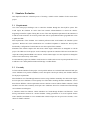
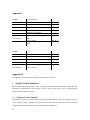
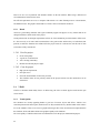
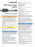
Messages sent on the bus are typically called a CAN frame and contains (up to) 8 bytes of data, an 11-bit
identifier (standard frame) and some additional required headers. The identifier specifies what kind of
message the frame contains and allows nodes to filter out message types that are not interesting. [11]. The
entire frame layout is seen in Fig. 2.
Fig. 2 CAN frame layout, [11].
11
2.8
Simulator
Simulated environments have been used for a long time and new applicable areas are continuously discovered
as the industry realizes the many benefits that, in many cases, include reduced costs and increased safety. In
later years sophisticated and realistic simulators have emerge with such impressive realism that it can be a
valuable tool for educational purposes. Simulators which include the same physical rules that apply to the real
world can with fairly high confidence predict correct reactions to user input manipulating the simulation.
NASA have been using simulators to prepare astronauts for space-flight for decades [12] and computer
hardware with sufficient performance is now available for common commerce. The main challenge for
producing a useful simulator is to achieve realism close to that of reality and it is especially hard to model
forces acting on a system causing realistic reactions of affected objects.
12
3
Hardware
This chapter describes the different hardware components that were used in the master thesis project. The
components will not be described in great detail and each section mainly focuses on relevant features and
facts with respect to its use in the project.
3.1
Potentiometer Sensor
A potentiometer, “pot”, with all three terminals connected, works as a variable voltage divisor, [13]. The
adjustable pot alters the resistance introduced in the circuitry and thus the voltage. The potentiometer can be
used as a position transducer and a common application is volume control. With the use of an analog-todigital converter (A/D) the potentiometer can produce a digital position relative to some initial reference.
3.2
Analog-to-Digital Converter (A/D)
An analog-to-digital converter (ADC) uses the magnitude of a current or voltage and transforms it into a
digital value, [13]. The range of the values depends on the number of bits available for the representation thus,
resolution is usually a number to the power of two. Common applications are plenty fold e.g. music recording
and conversion of sensor readings.
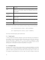
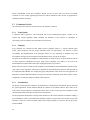
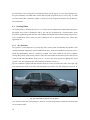
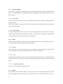
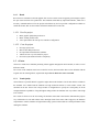
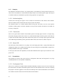
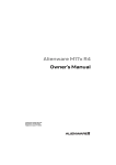
Fig. 3 Dell Alienware M17x.
13
3.3
Dell Alienware Laptop
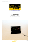
The Alienware m17x [14] is an eye-catching laptop from Dell seen in Fig. 3. It has an Intel Core i7 processor
with four cores working at a frequency of 1.60 GHz, 4GB RAM and dual ATI Mobility Radeon HD 4870
graphic cards combined with CrossFireX. It has a highs resolution 17” widescreen display and runs Microsoft
Windows 7 32-bit operating system. There are 2 USB ports located on the right side and 2 USB ports along
with one Ethernet port on the left side. The computer belongs to the performance segment of laptop
computers.
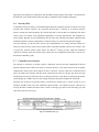
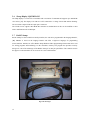
3.4
USB Interface Board
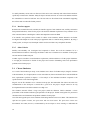
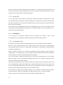
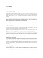
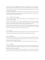
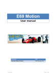
The Velleman VM110 USB Experimental Interface Board, shown in Fig. 4 (a), has several digital and analog
input/output connectors along with a USB connection, [15]. The USB provides easy connectivity with a
computer and also works as power supply. Velleman provides drivers and an SDK for communicating with
the board. The board also provides two analog outputs with a Pulse Width Modulation (PWM) option which
e.g. may be used to control steering servos.
Analog and digital signals can be converted with a general conversion time of approximately 20ms.
3.5
Freescale i.MX515
The i.MX515 logic board belongs to the category of Nano motherboards, and is shown in Fig. 4 (b). It uses an
ARM Cortex™-A8 processor and supports hardware accelerated OpenGL ES 2.0 and OpenVG 1.1 graphics.
The intended use includes Advanced HMIs and High-end PDAs. Linux (Ubuntu) and Windows CE is
supported and there are several different interfaces for connectivity, the most interesting being; USB, DVI,
Serial, Ethernet and LVDS, [16]. The LVDS transmitter only provides 18bit RGB data resolution as standard
and requires hardware modification to provide 24bit data resolution.
(a) Velleman, USB Experiment Interface Board.
Fig. 4
14
(b) Freescale i.MX515.
3.6
Sharp Display LQ123K1LG03
The Sharp display is a color TFT-LCD module with a resolution of 1280x480 and supports up to 24bit RGB
color values, [17]. The display is lit with two CCFTs connected to a voltage inverter that enables dimming.
The screen has a 20pin LVDS and a 6pin power connector.
The LVDS receiver supports 24bit RGB data resolution as standard however this can be modified to 18bit
with a modification to the LVDS input.
3.7
BASIC Stamp
BASIC Stamp is a microcontroller created by Parallax, Inc. and can be programmed in the language PBASIC,
[18]. PBASIC is based on the language BASIC and offers a high-level language for programming
microcontrollers. Parallax, Inc. offers BASIC Stamp Windows Editor programming software that can be used
for writing programs and transferring it to the controller’s memory. The program also provides necessary
debug tools. One of the advantages of the BASIC Stamp is its many IO possibilities. The controller used in
this project is built such that it can be accessed via a serial COM interface.
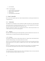
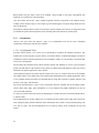
Fig. 5 The Prototype.
15
3.8
Mecel USBtoCAN Adapter
The Mecel USBtoCAN adapter supports USB v1.1 and enables an USB connection to communicate with a
CAN bus via a programming library provided by Mecel. The drivers support speeds from 33,3KB/s up to
1MB/s and Mecel offers the Mecel Datalink API that allows for creating new applications with the adapter.
The driver cannot handle multi-threaded applications at the time of writing.
3.9
Kvaser Leaf Professional
The Kvaser Leaf Professional enables an USB connection to communicate with a CAN bus via a library
provided by Kvaser, [19]. It supports USB v2.0 and CAN bus speeds from 5KB/s up to 1MB/s. Kvaser
provide the necessary drivers for most operating systems and the Kvaser CANLIB SDK for creating your own
applications with the Leaf Professional. It supports multi-threaded applications as long as each handle created
to a single device is only used in the one thread that received the handle.
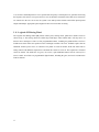
3.10 The Steering Prototype
The prototype is a miniature wheel axis controlled by two servos and can be seen in Fig. 4. It has three
potentiometer sensors that can be used as position transducers since they are attached to the wheel-axis and
will change its output according the axis position. The servos can be controlled individually via PWM signals
which are usually generated at 50Hz. Since the servos only exerts a force upon receiving an entire pulse there
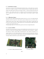
Fig. 6 Logitech G25 Racing Wheel.
16
is an obvious relationship between servo speed and the frequency at which pulses are generated. Increasing
the frequency will increase servo speed and vice versa. It should be noticed that since both servos and sensors
are connected to the axis via an arm, the system is not entirely linear and that could affect input/expected
output relationships. Appropriate pulse lengths will have to be measured via testing.
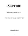
3.11 Logitech G25 Racing Wheel
The Logitech G25 Racing Wheel [20] consist of three parts; steering wheel, pedals and a shifter. These are
shown in Fig. 6. The steering wheel has a hard stop at 900-degree wheel rotation and a soft stop can be set
between 40 to 900 degrees. There are four programmable buttons, including two paddle shifters. The force
feedback uses dual motors and position sensors with high resolution. The force feedback requires that an
additional external power source is connected. The pedals are used for throttle, break and clutch and are
analog controls with different suspension to reassemble the controls of a real car. The suspension is fixed and
cannot be altered. The shifter has six gears, one reverse, eight additional buttons and one Point-of-View
(POV) control. All of these are programmable digital buttons, including the gears, and can be customized in
whatever fashion.
17
4
Methodology
This chapter explains the different phases of the master thesis project. From here on, simulator system refers
to all parts of the thesis solution while simply simulator refers to the driving environment.
4.1
Analysis
The analysis phase of the project was at first aimed towards obtaining a complete understanding of the already
existing system’s design. This was first done on a high abstraction level and as the different components were
identified, a low level understanding was pursued. After that point it was clear what major parts that would
be, or could be, included in the project.
It was important to identify the different requirements and constraints that already existed in the system and
reflect on how they could affect the final solution. The results of the analysis phase obviously affected the
final design of the project solution.
For reasons out of our control it was necessary to continue the analysis throughout the project as details
changed. This required minor design and documentation updates in order to be consistent with the actual
system.
4.1.1
Project Application
The main goal of the project was to create an application used for communication between the project
components and to keep this communication alive without sacrificing performance. This could either be done
as a process in the OS background or as a more complex application with a functional GUI providing better
user interaction and configurability. Both these alternatives have their own drawbacks and advantages
depending on project goals.
Using a basic system without a GUI would require less system resources and maximize performance of the
system. At the same time such a system would be less user friendly and contains less configurability.
Early in the project timeline, a GUI-based application was created because of the advantages in functionality
and user friendliness. Using a GUI was considered favorable since the Steer-by-Wire system would not be
completed prior to the end of the thesis and configurability was important. This was also a choice made to
ease the application development by featuring better debugging tools for all subsystems. The project had
subsystems which all had major differences in functionality which the user would preferably be able to
interact with in an isolated manor.
The consideration to use a GUI-based application was also a risk. The system is dependent on high
performance communication between subsystems, and the GUI should never be allowed to take priority over
these systems. Doing so would otherwise risk a low overall system performance. This is why the Windows
WIN32 API was chosen for the GUI rendering. The WIN32 API is built on low level C-functions which allow
18
simple GUI applications to be created without high performance loss, compared to say high-level frameworks
when updating the GUI.
4.1.1.1 Steer-by-Wire Model
Because development of the Steer-by-Wire system would not be completed during the application
development, an extra application was created to simulate basic functionality of that system. This was mainly
motivated for application testing purposes.
4.1.2
Simulator
To find a suitable simulator, the first phase of the analysis process was to find and setup functional and
nonfunctional requirements. Finding these requirements involved analyzing technical limitations, technical
preferences and evaluating what was required of the simulator in a demonstration environment.
The technical limitations are an important aspect of the system because they can be directly translated into
high priority requirements which must be met. Finding these requirements was done by analyzing the
necessary system interfaces to and from the simulator.
Technical preferences are medium or low priority requirements that specify what the simulator should feature
to enhance the experience and system performance. This could be different aspects of the simulator like
options, realism and visual quality. The fact that the thesis project will be used for demonstration purposes
also added additional requirements. These are typically nonfunctional such as visual quality, reliability and
stability.
The second phase of the simulator analysis process was focused on searching for matching simulators against
the requirements derived from the first phase. Only a basic comparison against the requirements was done in
this phase and was used to remove candidates unsuitable for the project. Most important are the high priority
requirements that contain the critical features that need to be included in a suitable candidate.
Searching for simulators include using Internet resources, school and company networks. The Internet is a
rich resource for finding software such as simulators and search engines were powerful tool for finding
suitable candidates. Community sites found on the Internet was also used to find suitable simulators. Because
of these factors, the Internet was the main resource for finding suitable simulators.
The Chalmers network was considered to be a large resource due to the research and project oriented nature
of the school, resulting in a vast amount of available resources. Using resources from Chalmers also meant
that developer communication and project source code was available in most cases.
The last phase of the analysis process was to evaluate the simulators found in the second phase. Here
requirements would be used to specify important criteria for a suitable simulator. These criteria are different
aspects of an optimal simulator suited for the project. Evaluating the simulators could then be done by
matching how well a simulator fulfills criteria of the optimal simulator by rating it.
19
Finally every simulator was rated and compared to the others. The result of this comparison was the choosing
of a simulator, the entire process is presented in great detail in chapter
Appendix D
4.1.3
HMI
Another visual part in the project was creating an HMI to show gauge data from the car dashboard in the
simulator. One of Mecel’s products is a tool named Populus Editor described in section 2.5, which is used to
create vehicle HMIs and was used in the project to create and design a HMI.
Development of the HMI was split into three different parts; deciding the visual components, determine
available simulator data and building the HMI. Deciding the visual components was much related to the
simulator chosen. All the features (gauges, indicators etc.) used in the HMI had to be available from the
chosen simulator.
The second part was focused on analyzing documentation in order to determine available simulator data. This
limited what visual components that could be implemented. Since the HMI will be used in a demonstration
purpose, it was considered important to be visually appealing and modern.
4.1.4
Steering Wheel
The steering wheel is one of the main components in the project and was used to provide the Steer-by-Wire
system with steering data. The steering wheel is described in section 3.11. From the Steer-by-Wire system a
wheel axis is connected and is described in section 3.10.
Except for providing the Steer-by-Wire system with data, the steering wheel must also keep itself
synchronized with the wheel axis. The steering wheel will likely become unsynchronized if Steer-by-Wire
suffers from a system failure and position the wheel axis away from that of the steering wheel. The steering
wheel must then attempt to align itself with the wheels since they are controlling the car and thus the driving
simulator.
Analysis of the steering wheel was first focused on how data should be sent to the Steer-by-Wire system.
From the project description the Steer-by-Wire system was supposed to use USB. The communication
actually consisted of a USB to CAN adapter described in section 3.9 so the data was sent and received over a
CAN bus. This required steering data to be formatted in a valid CAN format. The feedback received from the
Steer-by-Wire system was going to be used to regulate the steering wheel position, as explained above, and
was measured by the wheel axis sensor. This required the project application to translate the data from the
sensor to valid data used to position the steering wheel. After specifying steering wheel input and output, an
analysis began to search for methods to receive and transmit this data.
The Windows platform uses the DirectX DirectInput API to communicate with compatible controller
hardware, such as the steering wheel used in the project. On a Linux based platform there were no standard
APIs for such communication, but the Linux-community have created other solutions. These solutions had
20
some major drawbacks in functionality and reliability such as not supporting programming of the force
feedback. This supported the decision to use a Windows platform for the steering wheel communication.
Because DirectInput is a part of DirectX, the API is well integrated within the Windows platform which is
favorable to the process of creating DirectInput compatible software. Using the API required reading both the
DirectInput documentation and analyzing software samples. The Force Feedback also requires specific
knowledge about effects used to position the steering wheel, what data that could be used as input and how to
establish a connection to the steering wheel.
4.1.5
CAN
The Steer-by-Wire system uses a CAN bus to communicate with any surrounding hardware. The CAN
protocol is described in section 2.7.
Since PCs usually does not have the required serial interface, a USB to CAN adapter was used. At first the
adapters described in section 3.8 was used, however they suffered from a major driver drawback; it did not
support a multi-core processor. This was not realized until the system was tested on the multi-core Alienware
laptop described in section 0. A laptop was not available until late in the project. This caused other
alternatives to be found which resulted in the use of a CAN adapter from Kvaser, described in section 3.9.
This adapter featured multi-core support and was therefore compatible with the project system.
4.1.6
Wheel Sensor and Velleman USB Interface Board
To control the simulator and force feedback of the steering wheel, angle data from the prototype’s wheel axis
was used. From the project description, USB was described as the communication interface from the wheel
axis sensor to the PC. A strict interpretation of this would require the sensor to have a USB connection,
however this was not the case as it was simple potentiometer. Instead a Velleman USB interface board was
connected to the sensor through which data was acquired in a digitalized form to the project application.
4.2
Design
This section contains the design choices made during the project.
4.2.1
Basic Design
The programming language chosen was C and C++ which more or less was forced by the requirements of
performance and the hardware components supported interfaces. The design was focused around an ObjectOriented (OOP) pattern with high modularization in mind.
Circumstances required the application to be highly configurable in terms of being able to replace modules
and configure hardware components.
21
As a multi-core computer was used and timing constraints were present, the design was deliberately focused
on identifying independent execution loops which could be optimized using threads.
Since the final product will be used in commercial purposes and handed over to Mecel, there was a demand
for high quality documentation. This was achieved with UML diagrams such as conceptual models, class and
flow diagrams, but also rigorous code documentation.
The project application interface is mainly an administrative tool, but should be designed in such a way that it
is easy to use but yet offers a highly configurable environment.
4.2.2
Design of Application GUI
Using the WIN32 API, a simple Windows GUI was created with basic functionality to configure system
behavior and provide simple debugging tools for identifying any problems in subsystems. The GUI became
too complex for normal usage and a second GUI was created. This version used a high degree of code reuse
from the more complex GUI but with less functionality and was to be used in demonstration environments
where debugging features would not be necessary. Disabling the debugging features would also result in
increased performance of the system since they were excluded using pre-processor directives.
As explained in chapter 4.1.1.1, an additional application to simulate the Steer-by-Wire system was also
created. This application also has a GUI and was designed to reuse much of the code created in the previous
GUIs.
4.2.2.1 Debug Application
The first design of the application GUI was the most complex and included features for debugging system
functionality. Different designs were considered and the layout was focused around preserving the goal of
achieving a high modularization of code structure as set up in the section 4.2.1.
The GUI was designed to group modules into different sections where each section contains the various
functionality of the individual subsystem and a debug window separated from the other sections and used to
output data containing error codes, hardware changes etc. These were designed to contain configuration
parameters. Most hardware contains configurable parameters that should be set to successfully communicate
and these could change depending on the system setup. Therefore these parameters were included in the GUI
as well as a configuration file with parameters saved locally on the system PC. The application loads the
parameter on startup in the GUI and software.
Because the extra debugging functionality would require extra load on the PC, some design choices was made
to improve performance. The GUI uses a debug level parameter to specify how much data that should be
rendered in the GUI. This resulted in a GUI that requires less system resources with a low debug level and
vice versa.
The GUI also enables the user to choose the number of lines used in every debug output window. Using less
number of lines would require the GUI to render less information causing an increase in performance.
22
4.2.2.2 Steer-by-Wire Simulation Application
As previously explained in chapter 4.1.1.1, an extra application was created to simulate the Steer-by-Wire
system. The code base was designed to be similar to the other application, but with modified functionality.
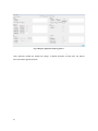
The GUI was also designed to look similar to the other applications, as shown in Fig. 14. Debug capabilities
was implemented and used with a debug level as explained in chapter 4.2.2.1. A configuration file was
designed to save configurable parameters used in the GUI and application software.
An additional section in the GUI was created to handle simulation of Steer-by-Wire failures and was created
with six different “error codes” in mind. These represents specific failures in the Steer-by-Wire system and
were unspecified during the project timeframe and therefore designed to be as generic as possible to allow for
future development of the system.
4.2.3
Designing HMI Interface
To create the HMI visuals several approaches were discussed; free graphics from Internet resources, already
built HMIs and available resources from Mecel. Using Internet resources, free graphic could be found to
design the visuals. High quality graphics suitable for the HMI was hard to find and this approach was
considered to result in less appealing visuals and therefore dropped.
Mecel had several HMIs built for other projects that could be used to create the HMI visuals. These featured
high quality graphic and was visually designed for the same purpose as the project HMI. Because of copyright
purposes, these HMIs were never used in the project.
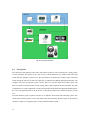
The Populus department of Mecel proved resourceful and a custom designed HMI could be created. A layout
guideline was established based on those shown in Fig. 7 and graphics was created by parts of the Populus
team. However, the underlying functionality and logic had to be designed and implemented within the
simulator project. This would be achieved via an introduction to the Populus Editor and studying related
material of how the Populus suite works.
4.2.4
Data Flow
From the steering wheel analysis described in chapter 4.1.4, the Windows platform and DirectInput API was
considered as the most suitable platform for the project application. This would require the project software to
be designed to support the DirectInput API. The system complexity would also require a specific data flow
through the system to avoid instability and failures. Without any consideration to this, system components
might be able to halt the application when not receiving input data.
The application was designed so that no system component would be able to halt the system even if no data
would be received. Using several threads the system was split into several subsystems individually executed
but still dependent of input data from each other. This would create a system that functions even if no data is
transmitted between subsystems.
23
(a)
(b)
(c)
Fig. 7 HMI concepts.
The data processed by different components also influenced the choice of what thread they should belong to.
Using commonly shared data between threads can cause unexpected behaviors and failures if not carefully
considered. To address this issue the application was designed to limit the amount of shared data between
threads.
4.2.5
Steering Wheel Software Design
The steering wheel was used to process both input and output data. The output data was to be transmitted as a
steering angle to the Steer-by-Wire system and input was used to synchronize position of the steering wheel
with the prototype wheel axis.
24
Designing a system where the steering wheel would be synchronized with the wheel axis and at the same time
not limit the steering to the driver were a considerable challenge and critical to achieve a good simulator
experience. Making the feedback force too strong would result in a difficult steering and too weak would let
the steering wheel get unsynchronized with the wheel axis.
Various force feedback effects, as explained in chapter 2.3.1, was used to balance the reaction between input
and output from the steering wheel. Measurement of the appropriate effect levels was difficult and required
extensive testing. Depending on the effects used and their parameters, the system experience would be very
different. The goal was to reach a combination of effects and a set of parameters as close to an optimal
solution as possible. The project application was also designed to provide configuration of the force feedback
effects.
Output from the steering wheel is used by the Steer-by-Wire system to control the prototype wheel axis. The
Steer-by-Wire requires this data to be converted into a specific range. Because this range might change the
input data was designed to be easily configurable.
Beside steering wheel position, various data such as throttle and break was received from the steering wheel,
however, only the steering angle was transmitted to the Steer-by-Wire system.
4.3
Implementation
The implementation process was focused on a close collaboration and rapid development. ClearCase© from
IBM™ was used to manage code delivered from different developers and ensured that a working build was
always available for integration. The focus was on frequent deliveries and continuous testing and verification.
Refactoring was encouraged when properly motivated and considered possible while still maintaining the
timeframe.
Since the programming languages used was C and C++, Microsoft Visual Studio was the obvious choice for
IDE. Visual Studio also has a seamless integration with ClearCase which seemed important to reduce
overhead created by version management.
4.3.1
Application Implementation
Implementation of the application was done using Visual Studio and VC++. The GUI was created using the
WIN32 API and the visual design was implemented using the resource editor in Visual Studio.
The actual implementation was based on a continuously updated class diagram in UML, where all classes and
methods were specified. Because there were parts written in C and UML is used for object oriented modeling,
the UML standard was somewhat deviated from, as it offered a more clear view. The final version of the class
diagram can be found in Appendix B
To aid implementing thread and system functionality, flow charts and system overviews were created with
Microsoft Visio 2007. This helped to obtain a correct view of system functionality and implementation
strategy.
25
System overview diagrams were created in both a detailed and simplified versions to help get an overview of
system functionality and communication channels.
4.3.2
Building the HMI
With the help of Mecel resources a specially designed HMI for demonstration purposes was created. Using
the Populus Editor the visual design could be implemented into a working HMI cluster. During the project
timeframe the Populus Editor was still under development and continuously received new features and
updates.
The Populus Editor is a specialized tool that requires training to learn. The Populus department had created a
training kit for clients using the editor which consisted of several tutorials focusing on different sections of the
editor. This training kit, along with an introduction, was used to learn the editor functionality and capabilities.
A simple prototype HMI used for testing was created with instruments suited for the simulator. The main
purpose of this was to prepare the application for the final HMI when the graphics were finished, but also to
test the connection to the simulator.
Controlling the components of the HMI is done by implementing an interface to the HMI database provided
by the Populus API. Creating software capable of connecting to the HMI requires knowledge about the
Populus database system and developing a flexible solution to retrieve data from the simulator and transmit it
to the HMI.
4.3.3
Concurrency and Threads
Several threads were used to split up the system functionality into different subsystems. Using these threads
would allow hardware to communicate in parallel and prevent software halts.
Within the system there are three different threads with different functionality. All threads were designed to
work as poll-and-send procedures with few shared dependencies to keep a high performance level.
4.4
Testing
Testing and verification was done in parallel with development. The high modularization allowed for easy
testing of individual subsystems as well as test of interaction between modules as they were finished. An
overall system functionality testing was performed at the end of the project where constraints and
requirements set up in the analysis/design phase was verified and signed off.
4.4.1
Test System
Without a functional Steer-by-Wire system completed within the project timeframe, a key component of the
simulator system would be missing and make it hard to test the full functionality of the system. A basic stamp
microcontroller was used to replace the Steer-by-Wire part to simulate a complete system with the wheel axis
26
prototype controlled by the simulator environment. Using such a test system was critical to detect failures and
problems only detectable in a full scale system test.
27
5
Simulator Evaluation
This chapter describes the evaluation process of choosing a suitable vehicle simulator for the master thesis
project.
5.1
Requirements
One of the main project challenges was to control the simulator through the Steer-by-Wire system. This
would require the simulator to retrieve data from external software/hardware to control the vehicles.
Supporting an interface capable of doing this was one of the most important requirements for the simulator. It
would also need an interface for accessing vehicle data such as speed, RPM and other gauge/indicator values
to update the HMI.
Most requirements of the simulator were technical preferences that would enhance the simulator system
experience. Realism and visual customization were considered important to simulate the Steer-by-Wire
functionality. Configuration of vehicle behavior was also required of the simulator.
Simulators often contain complex GUI and various vehicle angles which had to be changeable to suit the
project. The HMI used in the project would eventually represent the simulator HUD and would therefore
require the existing simulator HUD to be removed. Vehicle camera angles were also required to be changed in
order to remove unnecessary visual details.
For demonstration purpose the simulator would need to be reliable and not cause any unexpected behavior. It
would have to be a stable platform without critical bugs or sudden failures.
5.2
Pre-study
To find a suitable simulator for the project several possible markets was evaluated. Both commercial and open
source simulators were possible candidates, but also the option to develop an entirely new simulator tailored
for the project requirements.
Most simulators were found through Internet resources using simulator community sites and search engines.
Several open source simulators of varied quality were found while searching simulator communities. A lot of
them did not fulfill the critical requirements and were therefore removed without further evaluation. VDrift
and Racer were the most commonly used open source simulators chosen for evaluation and found through
various Internet search engines.
A simulator called The Chalmers Vehicle Simulator was found through Chalmers and featured a visual
driving environment connected to a motion simulator. During presentation of it several required features
where identified, and thanks to close communication with developers and an open source structure, it was
chosen for further evaluation.
28
Mecel recommended several other simulators. StageIT was one of these, and it was chosen for further
evaluation as it was visually appealing and focused on vehicle simulation. There was also an opportunity to
collaborate with the developers.
5.3
Evaluation Criteria
The following section describes the criteria chosen for simulator evaluation.
5.3.1
Visual Quality
A simulator used to represent a real environment and used for demonstration purpose, requires it to be
realistic and visually appealing. When evaluating the simulators to this criterion it’s capabilities of
representing a real environment and visual details were discussed.
5.3.2
Gameplay
Every simulator was evaluated for their features such as gameplay features, i.e. realism, different game
modes, menu complexity and GUI design. Simulators focus on representing a real world in a virtual
environment, but implementation of the gameplay features all vary depending on simulator focus and
development. Racing style and environment was important to find a good fit for the project.
The game modes featured in the simulators would preferably be simple ad focus on vehicle behaviors instead
of racing experience. Multiplayer and large single player campaigns were unlikely to fit well in the
demonstration environment where more light weight game modes were preferred.
Menus and GUIs were all evaluated in the simulators to find limitations and incompatibilities with the system
setup. These visual components would also be important for the demonstration experience which should not
be complicated and redundant. For example, the gauges and indicators of the vehicle were not supposed to be
displayed in both the HMI and simulator. The project would also benefit from certain menu options to allow
configuration of controller settings and adjust vehicle behavior.
5.3.3
Customization
The project would require the simulator to be customized for a demonstration environment and use data from
the system application. Several different methods are common for simulation software where APIs can be
used to allow external software to communicate with it. There are also several open source alternatives in the
simulator market that would allow for any kind of customization.
The most important characteristic to change in the simulator was the vehicle and track environment. Finding a
good combination of these could enhance the simulator experience to better fit the Steer-by-Wire system. The
simulators could also contain unwanted features that would preferably be removed, like the previously
mentioned HUD.
29
To modify simulator, various tools are often used. This can be tools commonly used in the software market or
specifically created for the simulator. Many developers include such tools to reach a wider market and allow
the communities to extend or build new ones. The best tools are often found in the communities supporting
the software and were therefore further pursued.
5.3.4
Interface support
Related to the customization tools available, the interface support of each simulator was carefully evaluated to
find possible limitations, critical for the project. The absolute minimum requirement of any simulator was to
allow external software controlling the vehicles and output data used in the HMI.
If no interface was specified to allow control of vehicles in the simulator, another alternative was further
investigated. DirectInput was used in the project application and are common among simulators. By using a
virtual joystick, see chapter 2.4, DirectInput could be used to send data to any compatible simulator.
5.3.5
Other Criteria
Stability and reliability was investigated and compared to discuss how well the simulators fit in a
demonstration environment. Critical bugs and failures could cause a simulator to be unsuitable for the project
and was therefore further analyzed.
Another aspect is simulator cost and hardware requirements, which would have to fit the project limitations.
A too high price would not be feasible for the project and visuals to demanding could cause performance
problems critical in the project.
5.4
Chosen Simulators
As a result of the simulator pre-study, seven simulators were chosen for further analysis; StageIT, Chalmers
Vehicle Simulator, Live for Speed, Racer version 0.50 and 0.88, rFactor and VDrift. These could all fulfill the
basic requirements specified in chapter 5.1. The analysis of the individual simulators compared to the
specified criteria can be found in Appendix .
StageIT was the first simulator to be evaluated in the project. Recommended from Mecel and with close
communication to the developers it seemed like a good fit for the project. StageIT wanted to do any
development themselves and this resulted in a too high cost.
The Chalmers network offered a long term project called the Chalmers Vehicle Simulator. A basic
presentation of the simulator indicated good potential to fit the project. Further investigation of it presented a
simulator with several limitations and problems endurable for the project.
One of the most popular open source simulators found using Internet resources was Racer. This simulator was
split into two separate versions, one open source and one closed source. The open source version was
discontinued since 2006, however, recommended by the developers to those wanting to understand the
30
underlying structure of the closed source version. Both versions were analyzed as the closed source version
would contain a larger set of features and while the other would feature a simulator open for further
development.
VDrift was another open source simulators evaluated. It focused on a drift racing style with an advanced
physics engine to support this. With a large community and great set of features it was one of the more
attractive and suitable simulators for the project.
The two commercial simulators rFactor and Live for Speed were both known for its high visual quality and
realism. Live for Speed focus on online racing but provides a rich set of features and customization options.
An editor featured in the licensed version can be used to create new track layouts with various obstacles.
rFactor is a simulator with focus on high speed racing and features several tools to modify the simulator
behavior and appearance. Both simulators had large and enthusiastic communities that helped to provide more
documentations and additional modifications.
31
6
Result
The following chapter presents the results of the master thesis project. The chapter is divided into a high-level
overview of the resulting system, followed by detailed descriptions of the various resulting subsystems.
6.1
System Overview
The resulting system is divided into two major parts; one safety critical and one simulator system. The
simulator system is focused around an application which coordinates data transfers and conversion between
the different interfaces A-E in Fig. 8. An in-depth overview of the interfaces can be found in Appendix A.
Interface A is used to communicate between the simulator Live for Speed and the main application. This
interface consists of two separate interfaces with are used for input and output. The functionality of interface
A is further described in section 6.2.
Interface B connects the steering wheel to the application and enables data collection from the Logitech G25
game controller. This interface also controls the force feedback and updating its necessary parameters. The
Fig. 8 Final System Overview.
32
Fig. 9 GUI – Release Version.
functionality of interface B is further described in section 6.3.
Interface C control output to the HMI and keeps the displayed information up-to-date. This is manly an output
interface and is further described in section 6.4.
Interface D is a CAN bus which enables the application to communicate with the safety critical system. The
bus also allows for feedback from the safety critical system to the main application. Interface D is further
described in section 6.5.
The last interface, E is a communication channel used to connect the wheel axis sensor to the application and
is further described in section 6.3.
6.1.1
GUI – Release Version
In order to control the application and its different subsystems a GUI was created as seen in Fig. 9. The
interface is divided into distinct parts and the amount of options is kept to a minimum. The different
subsystems can be enabled in any order, however, the user should follow the recommended boot sequence
that is based on the numbering of each section 1-6. Not complying with this standard will likely produce
unwanted results as subsystems inevitably depend on each other. Normally the ”Startup System” button
should be used which will activate each subsystem in the correct order and will alert the user if some
subsystem experiences problem. The GUI also has status indicators showing the user what subsystems active.
6.2
Simulator
From the evaluation process described in chapter 0, Live for Speed was chosen as the most suitable simulator
for the project. Its realistic representation of a real environment and focus on vehicle simulation matched the
project requirements. OutGauge was used to update the HMI, and DirectInput to control the vehicle steering.
33
Several features of Live for Speed were customized to better suit the project. A Volvo vehicle from the Live
for Speed community was added with a custom made car paint using Mecel logos, as seen in Fig. 10. With
use of the layout editor, explained in chapter 0, a track layout was designed and created to test the Steer-byWire performance.
6.3
Steering Wheel
The steering wheel, as described in section 3.11, is connected via an USB interface and the Microsoft DirectX
DirectInput API is used to communicate with it. The API was encapsulated in a Joystick module, which
provides the application specific functions. This includes all communication to and from the steering wheel as
well as initialization of the joystick and force feedback but also to perform cleanup of the effects upon
application exit.
6.3.1
Key Functions
The joystick is a vital subsystem as it provides the safety critical system, and ultimately the simulator, with
steering information and produces system feedback to the driver via the force feedback. The joystick’s state is
polled and intermediately stored at a frequency of 100Hz (each 10ms). When the new state is updated,
steering data (position of the steering wheel) is sent to the CAN module for transmission to the safety critical
system and all other data (throttle, brake, gear, etc.) is sent to the virtual joystick for updating the virtual
joystick’s state. The application flow is described in more detail in section 6.8.
The force feedback is updated with data from the wheel axis sensor provided by the safety critical part. The
most important part of this is the effect which attempts to prevent the user from turning the wheel too far
Fig. 10 Custom made car paint for Live for Speed.
away from the actual state of the prototype’s wheel axis. The following sections will describe the effects that
are used in more detail.
34
6.3.2
Force feedback Align Effect
An align effect was implemented to provide the necessary characteristic of the joystick’s steering wheel such
that it should always attempt to be in-alignment with current positioning of the prototype’s wheel axis. The
effect was achieved by using a spring effect as described in section 2.3.1.1 with an offset that is continuously
updated as the prototype’s wheel axis moves. The saturation is defined to be the maximum force that can be
generated by the device, with a dead band and positive/negative coefficients defined such that the maximum
force is achieved when the wheel is 60 degrees from the offset. The final settings were chosen such that a
large dead band and a high positive/negative coefficient will be used. This was done due to the currently
limited range of the prototype’s wheel sensor.
6.3.3
Force Feedback Dampening Effect
A dampening effect was created to prevent the driver from turning the wheel so fast that the align effect
described in section 2.3.1.1 could not keep up, and provides the driver with a smooth feeling when steering.
The effect creates a resistance that increases based on the velocity of movement generated from driver when
turning the wheel. This was created using the damper effect as described in section 2.3.1.2 with parameters
that introduces a small but noticeable resistance.
6.4
HMI
The Populus developers designed an HMI using the Populus Editor based on the dashboard concept as shown
in Fig. 11 (b), which features a racing style layout focusing on vehicle RPM and speed. Gauges and indicators
were designed to use data from the OutGauge interface provided by Live for Speed. The HMI is designed
indicators for several error codes from the Steer-by-Wire system.
Fig. 11 The final HMI design.
35
The Freescale i.MX515 logic board described in section 3.5. was used to display the HMI on the Sharp
Display described in section 3.6. When starting the i.MX515 a Linux-script is used to load the HMI engine
and set the correct parameters to enable output to the Sharp Display.
6.5
CAN
The CAN bus is connected via a USB to CAN adapter provided by Kvaser, as described in section 3.9. This
adapter is only used by the simulator system side as it is run on a PC. The ECUs are connected directly to the
bus since they have the necessary serial interface which the PC lacks. The CAN communication is
encapsulated in a module that provides all the application specific functions needed. This module handles all
communication to and from the CAN bus with the USB adapter. The communication directly with the device
is done via an interface provided by Kvaser.
The module, which initializes the CAN bus, provides configurable parameters such as bus speed. The default
bus speed is set to 1MB/s however that is configurable via the application GUI. The different messages
generated by the application are found in the CAN specification described in Appendix C
6.6
Sensor
The sensor information that flows to the simulator system comes from the logic board introduced in section
3.4. The board converts the analog input received from the potentiometer that is connected to the steering axis
of the prototype as described in section 3.10. The logic board is connected via USB to the simulator system
and is controlled via a module that handles all communication with it. The module provides all the application
specific functions needed and is based on an interface provided by Velleman.
The logic board can convert the analog signals to a digital value between 0 and 255. This is the maximum
resolution possible; however, the attached sensor on the wheel axis limits this range further. This has a
noticeable effect on the force feedback on the steering wheel and is further discussed in section 0. To
compensate for this a calibration function were created which determines the available resolution during
system startup.
The logic board is polled every 6-7ms and when the state is received and converted the data is used to update
the virtual joystick state and force feedback align effect parameters. Once the virtual joystick is updated the
simulator, Live for Speed, will have immediate access to the new data.
6.7
Virtual Joystick
A virtual joystick as described in section 2.4, was created using PPJoy. The virtual joystick has standard axes,
19 buttons and one point-of-view (POV) controller. Via an application specific interface and IOCTL calls, the
joystick’s state is updated as soon as any new data arrives. The virtual joystick is automatically detected and
seamlessly integrated into the Microsoft Windows 7 operating system and Live for Speed. Simulator can
36
therefor use this input without any modification of the source code. A virtual joystick interface is much faster
than a traditional IO interface and offers great performance which is important since it is dealing with delay
sensitive steering data.
6.8
Application Flow
The application deals with delay sensitive data and performance are obviously an issue. This was carefully
considered during the design and the system uses threading to reduce bottlenecks. The computer running the
application is described in section 0 and has several processor cores which enables true multithreading. The
flow chart shown in Fig. 12 illustrates the different threads that are run in parallel and their basic
functionality. The system can be divided into five major parts; joystick, virtual joystick, simulator (Live for
Speed), wheel axis sensor and HMI.
The steering wheel thread deals with polling the steering wheel, transmitting relevant data to the CAN bus
and updating the virtual joystick. This thread has an average execution time of 1ms and is executed every
10ms. This is currently limited by the microcontroller used in the testing system described in section 6.9. The
limitation is also discussed in section 0.
The wheel sensor thread handles polling of the logic board, updates of the force feedback and virtual joystick
state. These operations include some amount IO which takes a lot of time to execute and the thread has an
execution time of 6-7ms. On average the thread is executed every 7ms which includes a 1ms sleep.
The HMI thread polls the state of Live for Speed every 10ms and sends any updates over Ethernet to the
i.MX51, described in section 3.5. The i.MX51 updates the graphics shown on the display that is described in
section 3.6. F inally the simulator is run as its own process and has control over its threads.
37
Fig. 12 Application Flow Chart.
38
Fig. 13 Test System Overview.
6.9
Test System
Since the final system depends on the safety critical Steer-by-Wire in order to perform tests a testing system
was also developed. This system set up is seen in Fig. 13 and is deliberately very similar to that of the final
system from the simulator’s point-of-view. The only difference is that the Steer-by-Wire safety critical part
which controls the wheel servos has been replaced by a computer and a BASIC Stamp microcontroller. The
computer will receive steering data via the CAN bus, just as if it were the actual Steer-by-Wire system, and
then via a primitive transfer function convert steering data to a pulse length for the microcontroller. This data
is transmitted via a serial COM interface to the microcontroller which outputs the appropriate PWM signal to
the servos. The application that is run on the PC is called Steery Model and is further described in section
6.9.1.
From the simulator system’s point-of-view there is no difference between the final and testing system. This
should ensure that the system is correct and robust to the extent that when the final system is operational it
should be a simple case of plug and play to connect with the simulator system.
39
Fig. 14 Design of Application used for Steer-by-Wire simulation.
6.9.1
Steery Model
The Steery Model was created to replace the ECU part of the Steer-by-Wire system during testing, since that
system would not be ready. The Steery Model listens to the CAN bus via a similar interface as the one used in
the simulator system. It receives the steering wheel data sent by the simulator and converts steering data to a
timing which is sent via a serial COM port to the BASIC Stamp microcontroller which generates a PWM
signal to the steering servos. The servos react appropriately and wait for another PWM signal. The speed of
the servos depends on the frequency at which steering data is received on the CAN bus. All messages that are
older than 10ms from the time of sending will be ignored. This will normally not happen unless there is an
error on the bus.
The steery model can also transmit error codes back to the simulator to indicate any errors with the Steer-byWire. Currently these codes must be transmitted manually by pressing the appropriate button in the Steery
Model GUI seen in Fig. 14.
6.10 GUI – Debug Version
Beside the GUI described in section 6.1.1for the main application, a debug version was also created. This GUI
provides options similar to that of a debug tool and can assist in finding malfunctions in the different
subsystems. The layout of the GUI is very similar to that of the Release Version but with much more options
for each subsystem. There are several status bars that indicate current state of each system as well as output
windows with timestamps allowing the user to perform in-detail debugging if necessary. The amount of detail
that is printed to the user can be changed via a debug level indicator ranging from zero to two, where zero is
no output and two is maximum detail. It should be noticed that a high level of debug output requires lots of
system resources and should not be used to assess the final system performance. This is one of the reasons
40
Fig. 15 Design of application with debug features.
why a Release Version was created of the GUI. Another reason is that the debug GUI is too advanced and
offers options the normal user should never change. A detailed description is found in the user manual
delivered with the application bundle.
41
7
Discussion
This project included many different parts and custom purpose hardware which required us to gain knowledge
of several new areas such as CAN communication, i.MX51 and HMI creation. Getting hardware to work
together was time consuming and required some extensive studies of reference documents. One example of
this was getting the Sharp display to work with the i.MX51 logic board running Linux. The first problem was
getting any output to the screen at all since the display used the non-standard LVDS port instead of DVI.
When that was solved with support from Freescale (the i.MX51 vendor) it turned out that the number of
output bits was inconsistent with what the display expected. This resulted in an issue hard to track down and
in the end required hardware modification of the i.MX51 logic board.
Since the simulator is delay sensitive it was important to take this into consideration at an early stage. This
resulted in the use of threads that operates independently and will not suffer stalls due to synchronization
problems. Concurrent programming can introduce unexpected behavior which might be hard to track down
and it was established at an early stage that threads should be as isolated as possible with very few shared
states. This design paid off and the result was an application running smoothly and fast, thanks to the
powerful multi-core laptop.
Hardware set up for the HMI made it perfect to use the Mecel Populus Editor and Mecel Populus Engine.
Close collaboration with the Populus team resulted in a good looking HMI with a contemporary feeling. The
editor is a product under constant development and we made use of new features as they were released to us.
It felt important to be able to test the system in the most realistic way as possible since the Steer-by-Wire
system would not be ready within the timeframe of the project. Making use of the BASIC Stamp
microcontroller allowed us to hijack the prototype’s servos and the Steery Model used a simple transfer
function to control them in a similar way to that of the final system. The delay introduced by the Steery Model
and Basic Stamp is most likely similar to that of the final Steer-by-Wire system and tests have shown that this
delay is acceptable for the simulator.
Besides creating the main application itself, finding a suitable simulator felt like the part which would have
most impact on the resulting system. At least from a spectator’s point-of-view and this was important since it
is a demonstration system. Live for Speed had most of the parts we wanted from a simulator and a large
community connected to it. It is still being developed and future updates might benefit the project.
It was important to find an efficient way of communicating with Live for Speed since input would come from
multiple sources; Logitech G25 Game Controller and the wheel sensor. We did not have access to the source
code of Live for Speed and had to find a solution that allowed us to input data without the need to modify the
simulator. Searching for possible solutions resulted in using a virtual joystick which centralized input from
the simulator system’s point-of-view and integrated seamlessly with the environment. Creating our own
virtual joystick driver was estimated to require too much time and we resorted to using PPJoy; a driver which
appeared to be widely used, had the require efficiency and performance and was still being updated.
42
Overall, the resulting system fulfills the objectives set up in the introduction and it is our strongest belief that
it can be used to successfully demonstrate functionality of the final Steer-by-Wire system.
43
8
Future work
As the project came to an end and the final system was tested, ideas of improvements and additions emerged.
The most important improvement, mentioned in section 6.6, concerns the potentiometer mounted on the
prototype’s wheel axis connected to the Velleman logic board. The sensor is not configured to use the entire
possible range which limits the resolution of the already limited data from the logic board. This greatly affects
the force feedback in the steering wheel. Tests with a higher resolution revealed a considerable improvement
of the force feedback.
The HMI has all the basic instruments to that of a real car but as an addition, specific error messages/icons
from the Steer-by-Wire system can be added. This has been prepared for future improvements.
The frequency at which steering data is sent over the CAN bus is currently limited to 10ms. This limit exists
since the microcontroller that controls the steering servos of the test system, described in section 6.9, should
not send pulses any faster. This is because of limitation in the servos in collaboration with the steering model.
Once the real system is completed this limitation can be revised and decreased if necessary.
When the Steer-by-Wire and all other parts are finished, the project will include two of Mecel’s major
products – Populus (HMI) and Picea (Autosar on ECUs). By adding infotainment features, which could
include a music player that connects some mobile device via Bluetooth, the Mecel Betula suite would also be
included.
44
9
Bibliography
[1] Deon van der Westhuysen, PPJoy Documentation, 2010, Documentation received with downloading the
application.
[2] J. Stultz, T. Ts'o D. Hart, "Real-time Linux in real time," IBM Systems Journal, vol. Volume 47, no. 2,
pp. 207-220, April 2008.
[3] Michael
Horowitz.
(2009,
July)
Michael
Horowitz.
[Online].
http://www.michaelhorowitz.com/Linux.vs.Windows.html
[4] (2010,
Feb.)
Microsoft.com.
[Online].
http://www.microsoft.com/about/companyinformation/timeline/index.html
[5] Ted Pattison and Don Box, Programming Distributed Applications with COM+ and Microsoft Visual
Basic 6.0, Second Edition, 2nd ed. Redmond, United States of America: Microsoft Press, 2000.
[6] MSDN
Windows
Developer
Center.
[Online].
http://msdn.microsoft.com/en-
us/library/ee416842(VS.85).aspx
[7] Felipe Arango, El-Sayed Aziz, Sven K. Esche, and Constantin Chassapis, "A Review of Applications of
Computer Games in Education and Training," in Frontiers in Education Conference, vol. 38, Saratoga
Springs, 2008, pp. T4A-1 - T4A-6.
[8] Microsoft.
Microsoft
Windows
Developer
Center.
[Online].
http://msdn.microsoft.com/en-
us/library/bb153254(VS.85(.aspx
[9] Mecel AB. (2010, May) At the forefront of automotive technology - Mecel AB. [Online].
http://www.mecel.se
[10] Fred Seidel. (2009, 25) X-by-Wire. Document.
[11] Robert I Davis, Alan Burns, and Reinder J Bril, "Controller Area Network (CAN) schedulability
analysis: Refuted, revisited and revised," Real-Time Systems, vol. 35, no. 3, pp. 239-272, April 2007.
[12] James Oberg, "Astronaut," World Book Online Reference Center, 2005.
[13] Allan R. Hambley, Electrical Engineering, 3rd ed.: Prentice Hall, 2004.
[14] DELL. (2010, May) Alienware Computers. [Online]. http://www.alienware.com
[15] Velleman. (2010, May) Velleman. [Online]. http://www.velleman.eu
[16] Inc.
Freescale
Semiconductor.
(2010,
April)
Freescale.
[Online].
http://cache.freescale.com/files/32bit/doc/fact_sheet/IMX51EVKFS.pdf?fpsp=1
[17] T. Naka, Sharp Specification, 2007, Device Specification for TFT-LDC Module. Model No.
LQ123K1LG03.
45
[18] Parallax Inc. (2010, May) Parallax. [Online]. http://www.parallax.com/
[19] Kvaser. (2010, June) Kvaser - advanced CAN solutions for hardware, software, consulting and
education. [Online]. http://www.kvaser.com/
[20] Logitech. (2010, May) Logitech. [Online]. http://www.logitech.com
46
Appendix A
Fig. 16 Detailed System Overview
Appendix B
47
Fig. 17 Class Diagram
48
Appendix C
Sender:
FUSS Application
Receiver:
Steery
Physical Interface:
USB -> CAN
Transfer Protocol:
CAN
Data Specification:
Steering Angle [ (-10000) - 10000 ]
Throttle {0, 30, 90}km/h
Data Structure:
Frame 1 Steering wheel angle
CAN Id =
4 bytes
1
Frame 2 Throttle
CAN Id =
4 bytes
2
Sender:
Steery
Receiver:
FUSS Application
Physical Interface:
CAN -> USB
Transfer Protocol:
CAN
Data Specification:
Error code [ 1 – 6 ]
CAN Id =
Data Structure:
Frame 1 Error_ID
4
Appendix D
This appendix contains a detailed description of the simulator evaluation.
1
StageIT Vehicle Simulator
StageIT featured great visual quality, scaled-off gameplay and opportunities for further customization. The
simulator was demonstrated by the developers and was a nice fit to the project. Due to a limited project
budget, StageIT could never be used.
1.1
Chalmers Vehicle Simulator
The following evaluation is based on the experience from a demonstration given in the Chalmers laboratory
of the Chalmers Vehicle Simulator. The source-code given from the developers was never successfully
compiled and could therefore not be tested in other computer environments.
49
1.1.1
Visual Quality
The simulator looks unrealistic due to unrealistic and blurry textures. The environment lacks detail and the
vehicle models are very basic. For the demonstration purpose this was below the preferred level of visual
detail.
1.1.2
Gameplay
The simulator has no controllers implemented in the software; instead this is controlled externally via a
Simulink model. In the software the controllers therefore only provide a steerable view from a static setup of
controllers. There is collision detection on the surface implemented, but not on the external objects in the
environment.
The only menu available in the simulator is a configuration menu that is shown before starting the application.
The lack of menus was not really considered to be a problem for the project, but the lack of configuration of
controllers and HUD was a drawback.
1.1.3
Customization
Chalmers Vehicle Simulator is built on OpenSceneGraph (OSG) which is open source. The source-code of
the simulator is available to all students registered at Chalmers.
1.1.3.1 Development Tools
Except for the source-code, there are some external tools available such as a track editor. Because of run-time
errors these tools could not be tested.
1.1.3.2 Open Source
The source-code of the simulator was available for further development and based on the OSG project.
Because important references to external libraries were not included the source code could not be compiled.
These libraries belonged to old versions of the OSG project that are no longer available or supported through
other resources.
1.1.3.3 Community
The only community available was the developers of the vehicle simulator and students that have worked
with the system. The developers of the original simulator software were not working on the project anymore
and were therefore not active to support the project.
50
1.1.4
Interface support
The simulator is mainly used to communicate with a Simulink model and this is the only standard interface.
There is no implementation of DirectInput which makes communication with external devices an issue and
PPJoy unusable.
1.1.4.1 Data input
The input data to the simulator comes from a Simulink model that reacts with the vehicle platform and
simulator feedback.
There was no support for external devices within the simulator, but this communication layer could be added
via the open source format.
1.1.4.2 Data Output
The output data from the simulator was used to steer the vehicle platform. There was also data used to give
feedback to the Simulink model. The data sent as output is not known, but communication of simulator data
could be added even if that would be somewhat time-consuming.
1.1.5
Other
Chalmers Vehicle Simulator is open source but not initially intended to be used as standalone software, but
it’s instead meant to be used together with the vehicle platform.
1.1.5.1 Bugs
The simulators loss of collision detection made the simulator feel somewhat awkward and unrealistic.
Vehicles could drive through each other without any effect on the simulator physics.
1.1.5.2 Cost
Chalmers Vehicle Simulator is open source for Chalmers students and therefore free of charge when used
within Chalmers projects. For further use outside of Chalmers an agreement would have to be made with the
creator.
1.1.5.3 System Requirements
There were no official system requirements stated.
1.1.6
Result
The Chalmers Vehicle Simulator didn’t feel suitable for the project. It lacked graphical detail, realistic
gameplay implementation and its purpose was not intended to be used as standalone software. The source51
code was hard to compile and even running the simulator resulted in run-time errors. It was obvious this
simulator was not suitable for the project.
1.2
Live For Speed
Live for Speed is advertised as a highly realistic simulator mainly focusing on online racing. The simulator is
highly active with continuous updates to the simulator as well as a large and active community.
This evaluation was mainly based on the Live for Speed demo available on the official website. There was
also a small part of the evaluation that required a licensed version of the simulator.
1.2.1
Visual Quality
Live for Speed has an overall high visual quality with both realistic environments and vehicles, as well as
close to industry standard level of effects, textures, models etc.
Because of the frequent updates to the simulators, it’s visually appealing and modern. The menus did look a
bit plain, but that was the only minor complaint visually.
As a result, the realistic look of the simulator was considered to suit the demonstration purpose very well and
was one of the most visually attractive simulators chosen for evaluation purpose.
1.2.2
Gameplay
Live for Speed is famous for its high degree of realism and large number of settings. It features many game
modes and options for controllers, tracks and vehicle behavior.
1.2.2.1 Realism
Realism is one of the main features of Live for Speed. All vehicles use a realistic physical model that can be
customized in the menu system of the simulator. Also featured is a well implemented collision detection
which adds a nice touch to the simulation.
Because of the high level of realism in Live for Speed, effects of hazards and behavior of the system in
general could be simulated in a realistic manner.
The possibility to customize the physical model of the car from the simulator menus was considered to be
useful to make the driving experience better fit the Steer-by-Wire system limitation.
One drawback was the lack of options to disable physical models to remove complexity from the simulator.
1.2.2.2 Game modes
The simulator offers dozens of game variations like single player levels, training levels and multiplayer with a
lot of options and level variations. There were also about twenty vehicles to choose from in the simulator with
various setups and attributes.
52
Because of all the various options and game modes included in Live for Speed, the driving environment could
be could be customized to fit the demonstration needs. Using an empty track with small obstacles would be
possible to achieve and suitable for demonstration purpose.
1.2.2.3 Menus/GUI
Live for Speed features various menus to customize the simulator look and feel. The main-menu was clean,
but should preferably be customized to disable the multiplayer or training mode. Except this small drawback,
the menus would allow users to customize the simulator in many various ways that can be useful to really test
the Steer-by-Wire capabilities.
The interface was very customizable from the menus. Everything from vehicle views to GUI-settings could be
fully customized and enabled/disabled and often set to use alternate settings. This was considered to be very
useful for the demonstration purpose.
1.2.3
Customization
Live for Speed is a closed-source simulator where the developers have decided to release various
development tools to the community to allow any customization of the simulator experience.
1.2.3.1 Development Tools
The official tools are InSim, OutSim and OutGauge that can be used to communicate with the simulator.
There are a couple of formats specified on the webpage for Mesh export, replay analysis, racing information
(laps, simulator version, car name etc.), flags (gears, laps, penalty etc.), track layouts, and car information
(suspension, momentum etc.).
InSim is an interface written for Live for Speed to communicate with the simulator by either requesting or
sending packets. It uses either UDP or TCP to communicate with the simulator. InSim also allow keypresses
from a keyboard to be sent to the simulator through various packages.
Also a part of InSim is OutSim and OutGauge. They use the same communication but is used for other
purposes. OutSim is used to control motion simulators connected to Live for Speed. OutGauge is used to
retrieve data from the gauges in the simulator.
When using a licensed version of Live for Speed a track editor called AutoX can be used. This editor can be
used to add and modify AutoX created objects in the various simulator tracks and save these as layouts. The
user can only edit objects added to the layout file and not the existing objects of the track. Checkpoints, startpositions and other simulator functionality can also be added with AutoX.
The simulator also supports various different formats used to customize or interact with the simulator.
Formats available are CMX, RAF, SPR, MPR, CAR, DDS, PTH, TXT, SET, LYT, DRV and BANS.
CMX is a format used for mesh-export and is best used with the supplied CMX viewer.
53
RAF is used to analyze the replays recorded from different played races.
SPR contains information about the current lap in progress for a specific player.
MPR contains information about the current race in progress.
CAR contains information about a current vehicle and its setup.
The DDS format contains textures and can be used with Photoshop or Paint Shop Pro to be edited. The
textures in the simulator are everything from objects to vehicles to tracks.
PTH is used for path nodes that describe the track layout with the use of different data points.
TXT are language files and contain translations for menus and in-game texts.
SET used to set different aspects of the simulator vehicle settings like passengers, suspension etc.
LYT changes the track layout and is mainly used in the Autocross editor.
DRV contain data on the AI drivers in the simulator like the name, number of AI drivers etc.
BANS are used to ban people within a Live for Speed server.
Documentation about the different tools were somewhat lacking. The homepage did not describe the formats
usage or how to use the formats to customize the different aspects of the simulator.
The community is the best tool to provide information about the tools.
For the project, the development tools were enough to control the most important aspects of the simulator but
do not allow full customization of every aspect in the simulator. The AutoX editor could be used to customize
the tracks but would not be enough to completely tailor the simulator to fit the project preferences.
The communication interfaces and packet formats are specially created to be used in multiplayer over internet
but features data which could be very useful for the project. OutGauge was especially interesting because it
could be used to send data to the HMI.
1.2.3.2 Vehicles
The CMX viewer was useful to visualize the vehicle textures, models and skins to use in the simulator. The
CMX format was also compatible with common 3d modeling application like 3d Studio Max©, but there were
no information found about user created CMX-files that can be used within the simulator. There were
therefore unknown if new vehicles could be added to the simulator.
For the project adding new skins to existing vehicles would be sufficient.
There were some small community projects that work to develop tools to create new meshes of vehicle and
import into the simulator. Because of the big variations of vehicles provided, adding skins to existing meshes
would be sufficient.
54
1.2.3.3 Tracks
AutoX is the main tool to edit the tracks within the simulator. This tool can only add new objects and not edit
the existing ones provided with the original track. But there are specific parts within some of the tracks
specifically created to use with the AutoX editor that are more open and contain no objects.
There were no tools to edit the height maps or texture mapping of the track which limits the track
customization.
1.2.3.4 GUI
Live for Speed did not include any tools to edit the simulator GUI except for some menu settings. These
settings were quite extensive though, and most GUI components could be changed and tweaked to fit user
preferences.
There were no tools available in Live for Speed to modify the menus.
1.2.3.5 Community
Live for Speed has a large and active community where many new add-ons and features are added on daily
basis. The community is mainly found on the official forum where most add-ons, skins and tools can be
found.
1.2.4
Interface support
Live for Speed use InSim to communicate with other external interfaces. The interface supports various data
to be sent to any external software and also transmit data to the simulator.
InSim also provides two interfaces called OutGauge and OutSim. OutGauge is used to request simulator
gauge values and was a perfect fit to use for the HMI. OutSim is used to control motion simulators and would
not be very useful for the project.
1.2.4.1 PPJoy
Live for Speed localizes Windows game devices compatible with DirectInput. PPJoy could therefore be used
together with Live for Speed without any difficulty setup.
1.2.4.2 Data input
InSim is the main interface to use to send commands to Live for Speed. Most data specified in the InSim
protocol was not very useful for the project, but could have future potential when extending the system
functionality.
Live for Speed use DirectInput to communicate with external steering devices and support most controller
types (keyboard, mouse etc.). It was unknown if a fully working solution to directly communicate with the
55
steering in-game, i.e. not using PPJoy, was available, but the simulator was able to register key-presses from
outside software using InSim.
1.2.4.3 Data output
InSim is used to retrieve data from the simulator instance about the current race, vehicle information and
other data related to simulator status.
OutGauge is used retrieve information that can be used to show in-game gauge data.
1.2.5
Other
Live for Speed is closed-source and requires a license to unlock all options in the simulator.
1.2.5.1 Bugs
The simulator could sometimes react unrealistic to collision with certain barriers causing the vehicle to fly
high up in the air spinning. This was a known problem on the Live for Speed community but had not yet been
fixed.
1.2.5.2 Cost
The license for the newest version of Live for Speed was about £24 and then all content would be unlocked.
The license was required if the simulator was going to be used in a commercial environment. Using Live for
Speed in the project would therefore require a license.
1.2.5.3 System Requirements
Live for Speed has no official system requirements but instead refers to an official benchmark that can be
used to test system performance running Live for Speed.
1.2.6
Live for Speed Verdict
Live for Speed is a good looking racing simulator with a very realistic physical vehicle model. The simulator
could contain limitations to fully customize the simulator to suit the project, but the core functionality was
enough to provide the customization options needed within the project.
1.2.6.1 Pros for project
56
High graphic quality
Realism in physical model
High level of customization
OutGage makes HMI output easy
Great community
1.2.6.2 Cons for project
1.3
Hard to customize tracks and menus
Maybe to realistic steering model
Not open source
None comprehensive documentation
Racer Version 0.50
Racer version 0.50 is a popular open source vehicle simulator that features a realistic physical model and a lot
of modification tools.
1.3.1
Visual Quality
The simulator uses an old OpenGL version to render the 3d graphics. The textures were quite grainy and the
vehicle models and track environment lacked detail. There were a few effects implemented in the simulator
like smoke and lens flares which did add some realism to the visuals.
The project could benefit to upgrade some visual details like the textures, vehicle and object models etc. but
would be usable for the project in its regular appearance.
1.3.2
Gameplay
Racer has a robust and flexible physical model implemented to provide the simulator with a realistic feel. The
simulator features a very simple menu system to quickly go into racing mode.
1.3.2.1 Realism
The gameplay mechanics of Racer was pretty simple, but there was a physical vehicle model implemented. It
lacked the realism and feeling of a real vehicle, but the basics were there.
There were several customization possibilities for the physical model of the vehicle and featured about fifteen
different physical forces at every vehicle to customize. There was also a basic collision detection engine
implemented.
Below the recommended level, Racers realism would still fit the project purpose. The customization options
were quite flexible and would allow the vehicles to behave more natural and suitable for the project.
1.3.2.2 Game modes
The simulator includes two different racing modes; quick race and multiplayer. There were only one track and
one vehicle included in the simulator which all was very basic.
57
The game modes and options provided within the simulator were by default quite limited, but at the same time
simple enough for the project.
1.3.2.3 Menus/GUI
Both the menus and GUI in Racer were simple and clean. There were not many options available from the
simulator menus but instead most configurations were made from external tools.
The simplicity of the menus fit well with the project. Instead of confusing the user with unnecessary menus
these were very straight forward. At the same time the menus were very limited and customization options of
in-game interfaces, controllers etc. were very few.
1.3.3
Customization
The simulator is open source and has been created with customization in mind. There were a few external
tools provided with the simulator as well as various formats to include user created tracks and vehicles. There
were also a lot of add-ons to be found on the web.
1.3.3.1 Development Tools
There are six different tools to help customize the simulator experience. These tools are mainly used to export
standard format data to Racer compatible data.
GPLex is used to import 3DO-files and export them to Racer data.
Carlab is a tool used to modify simulator vehicles, both the graphics and physics.
Curved is used to edit curves used for vehicle physics, like different traction/brake-forces or motor torque
production.
Modeler can preview models from the simulator and enhance them in different ways. The tool allows any user
to modify material attributes like reflection, diffuse, colors and material transparency. It can also be used to
export models to other formats, better optimized for the program.
Pacejka is a tool related to Curved which allows to setup relations between forces, side load and momentum.
It’s an advanced tool that mathematically tweaks the behavior of vehicle tires.
Tracked is used to import models, add timelines, grid positions etc. to make a track compatible in Racer. All
tracks are made up off many different sections which contain objects information, model information,
geometry, spline definitions and racing data (grid, sky, cameras etc.).
Beside the tools previously mentioned, there were more tools available from community sites. One of these
was the Racer Track Creator that could be used to create a simple track without the use of any expensive
software. This tool was in early development when tested and was in need of further development to function
properly.
58
Documentation for the tools was provided on the website and contained detailed information about the tools
as well as various examples. There were also community documentation available to help get started with the
tools.
For the project these tools would provide excellent functionality to modify and add missing concepts. Still
these tools were somewhat flawed and hard to use.
1.3.3.2 Vehicles
The main tools to create and edit vehicles in the simulator are Modeler, Pacejka, Carlab and Curved. These
tools provide great capabilities to edit vehicles and allow adding everything from vehicle meshes, texture,
physics and material attributes to the simulator. The formats are standard that and be used together with
standard tools like Maya and 3d Studio Max. The physics model can also be changed into deep detail.
Using the tools provided could be excellent for the project to add and edit existing vehicles. The only minor
problem was instability and complexity.
1.3.3.3 Tracks
As with the vehicles there were an excellent set of tools to edit the tracks. The tracks provided with the
simulator were possible to change and with use of standard modeling applications, modifying and adding
tracks to the simulator were possible. It’s also possible to add tracks from other simulators compatible with
certain formats.
The tools used for track customization could be used to provide a custom-tailored driving experience in the
project with tracks built to test specific capabilities of the Steer-by-Wire system.
1.3.3.4 Open Source
One of the biggest advantages of Racer 0.50 was its open source format. The full source-code was available
and could be edited free of charge. The official site didn’t support Race 0.50 any longer and did not therefore
provide sufficient information about compilation requirements.
When testing Racer, the code was no longer being updated and contained an old code base without new
features and settings. This was considered as a major drawback making the simulator less future proof.
With the open source format the ability to edit all menus was available. Already quite simple and clean, the
menus could be customized to fit perfect with the project.
1.3.4
Community
The simulator community was somewhat active during the testing and using the official forums a lot of
information about the provided tools was given. There were also a lot of different sites available with new
tracks and vehicles compatible with the simulator.
59
1.3.5
Interface support
Racer use standard libraries to support input data from external controller devices. Using Windows, the
DirectInput interface is used to communicate with any external devices which make the simulator compatible
with PPJoy.
Because the simulator is open source, new interfaces could be created to send and receive data to the
simulator and by doing so, bypass the PPJoy software and directly send controller data to the simulator.
The simulator didn’t contain any specific interface for data output and this must therefore be added separately
in the source-code with some communication protocol.
1.3.6
Other
Racer 0.50 contains source-code from an old version of the simulator and is still in a beta state. This made the
simulator somewhat unpolished and there were various graphical bugs as well as problems in the provided
tools. The most obvious bug was lens flares causing screen flashes when visible.
The external tools contained a bug where the popup windows would disappear beneath the edit view area
(graphical area) and couldn’t be selected. This caused the tools to act as if they are frozen and couldn’t be
used.
Racer 0.50 is free to use if the purpose is none-commercial and won’t be redistributed. For commercial use a
license agreement can be bought through contact with the simulator creator.
No hardware requirements for the simulator were specified on the official documentation, but the test system
had no problem running the simulator with descent performance.
1.3.7
Racer 0.50 Verdict
Racer 0.50 was considered as a descent racing simulator which main advantage would be the open source
format. The tools included add a lot of customization possibilities for the project and would allow track,
vehicle, interface modification and a lot more.
For the demonstration purpose the simulator would require some large modifications, but these would allow
the simulator to suit the project needs very well.
1.3.7.1 Pros for project
Highly customizable thanks to good set of tools and open source format.
Good physics model implemented that allow every force to be edited manually.
Good community with many different add-ons available.
1.3.7.2 Cons for project
60
No longer supported by the developers.
1.4
Simple and old graphic.
Some bugs discovered in the editing tools and in-game engine.
No implemented interface for output data could take some time to add.
Racer Version 0.88
Racer version 0.88 is the newest beta released for the simulator. Since version 0.50 the source code is no
longer available for newer versions so this version is only closed-source.
Version 0.50 was released in 2005 and this latest version of the simulator was released late 2009 and has
therefore got some big improvements since 0.50.
1.4.1
Changes from Version 0.50
The graphical quality was more up to date since 0.50, but still behind the industry standard. Added effects like
HDR, Bloom etc. made the simulator look better and more realistic, but the textures and objects would still
lack detail.
The simulator has since version 0.50 also got a better menu system with various new options added to the
simulator menus and a new improved controller setup available. Still there was no GUI configuration
available at all from the simulator settings.
Quick Race is one of the new game modes added since 0.50, which includes different race options like
number of AI-drivers, track selection, number of laps etc. The other game modes are pretty much the same as
in version 0.50, with multiplayer not tested as this is unnecessary for the project.
Old vehicles from version 0.50 are removed in the new version, and instead there are two different vehicles
available. The default vehicle was a high performance vehicle with fast acceleration and speed, which wasn’t
very appropriate for the project. The other vehicle was a baja racer which was used for off-road racing. No
new tracks were available; instead the old track from version 0.50 was still in use and looked pretty much the
same as the old one.
The external tools had some annoying problems in version 0.50 where certain pop-up windows would be
hidden behind the view area and result in an application failure, which were fixed in the new version. Beside
stability improvements, the tools looked visually the same as their old versions, except Carlab which was
removed.
Because of the continuously upgraded graphics engine, the test system had some performance problems
running the new version. Choosing higher the texture quality from the simulator menus resulted in application
failures. Instability in the simulator menus was also more frequent causing the simulator to quit without any
valid reason.
61
1.4.2
Result
Racer 0.88 was considered a descent upgrade from version 0.50 but is not an upgrade good enough to replace
the open source structure of its predecessor. The simulator still lacked any output data interface, which was a
necessary communication tool for the project and without any obvious possible configuration available to
enable this feature; this version could be somewhat cumbersome to work with.
1.4.2.1 Pros for project
Better graphic quality than predecessor.
Better working external tools.
A new option menu for more precise controller configuration.
1.4.2.2 Cons for project
1.5
No longer open source.
More crashes than predecessor.
No output data format from the simulator.
Vehicles are not very well suited for project.
New menus just add more interface complexity.
rFactor
rFactor is a closed source simulator promising realistic graphic and physical vehicle models, as well as a lot of
different content.
The version of the simulator tested was not the full version, but instead the demo version included with the
Logitech G25 PC Steering Wheel, explained in chapter Error! Reference source not found..
1.5.1
Visual Quality
rFactor features a powerful DirecX 9 graphics engine that run the simulator. Tracks and vehicles available in
the simulator were detailed and the simulator use high resolution textures to create realistic visuals. The
simulator let the user choose from a large amount of configurations to specify the visual quality to fit the
computer hardware capabilities. Using the highest settings makes the simulator look very realistic with a high
level of detail.
The visuals of rFactor were the best among all simulators tested and would suit the demonstration purpose
very well thanks to its rich and realistic looks. But high visuals often comes with a high price; the hardware
requirements to run the simulator are high and the testing system could not deliver a stable performance when
running the simulator.
62
1.5.2
Gameplay
rFactor is a simulator constructed to deliver a realistic racing experience for both home environments as well
as industry hardware/software.
1.5.2.1 Realism/simplicity
Using an advanced physics engine, the simulator focuses to deliver a realistic racing experience. There are
configurations available to adjust the aerodynamics, advanced tire modeling and physics implemented for the
vehicles and their traction on the road. The realism in the simulator can be limited by using steering and
braking aid.
The simulator physics and visuals would allow the project to represent the Steer-by-Wire system with a
realistic representation of its behavior in real life environments. If the realism would be too high and cause
steering problems, the steering aid could be helpful to limit these problems.
The vehicle physics could be changed from within the simulator with a flexible set of configurations ranging
from basic settings to advanced vehicle modification.
1.5.2.2 Game modes
The version used for testing featured four different game modes; testing, race weekend, race season and
multiplayer where the last two game modes were disabled in the test version.
The testing mode would let the driver choose a track and vehicle to cruise around the track without or with
opponents. There was also a garage available to customize the vehicle setup in detail in this game mode.
Race weekend and race season focus on simulating a real racing environment with a practice and qualifying
round, as well as several warm-up and race sessions. Race season is a larger variation of race weekend where
the driver will be competing for a top position on a set of different courses.
The only game mode that could be usable for the project was the practice mode free from driver distractions
and better focus on vehicle behavior.
Vehicles and tracks are locked in the simulator and can be unlocked only if certain tracks and game modes are
completed. This also applies to the upgrades of every vehicle that can increase the handling and overall
performance of each vehicle. Using rFactor in the project would require all tracks and vehicles to be unlocked
so that every possible track and vehicle combination could be tested to best represent a good virtual test
environment.
1.5.2.3 Menus/GUI
The simulator features a basic set of menus with various configuration settings for controllers and graphics as
well as a racing rule settings menu. The simulator GUI could be customized using various settings, but the
63
RPM, throttle and gear gauges could not be disabled. Using an HMI as the gauge representation, this
limitation was considered as a major drawback.
Over time rFactor has become a more commercial product which was noticeable in the simulator menus.
Loading screens contain a large set of developer logos and small snippets of in-game racing which felt out of
place for the project.
Preferably the simulator menus would be customized to skip the loading screen movies (or change these) and
just include the options menu and practice mode, remaining menus felt unnecessary for the project.
1.5.3
Customization
rFactor is not open source but features a large set of customization tools and an active community
continuously releasing new add-ons to the simulator.
1.5.3.1 Development Tools
From the official website a set of tools can be downloaded to customize the simulator experience. This
includes tools to edit waypoints, in-game cameras, view tracks/vehicles, 3d Studio Max plugins, and tools to
communicate with the simulator application. From community websites it’s also possible to download other
tools to use in development.
The developer files submitted on the official websites includes four different set of tools. Tool provided to
prepare and edit meshes in the simulator comes packed in a MAS-format with material, texture and vertices
information for gMotor applications, such as rFactor.
rFactor Mod Development Tool Pack includes a MAS scene viewer to visualize the tracks in the simulator
and a MAS utility to create MAS archive files which contain information specific gMotor applications. There
is also a gMotor material and texture tool included that can assign basic materials to gMotor primitives and
textures to each stage of the materials.
The rFactor Internal Plugin is used to receive information from the simulator like the orientation matrix,
vehicle status, driver input, wheel information etc. Force feedback and graphic information can also be
received from the simulator.
To create new vehicles and tracks, the rFactor Max Plugin is available and can be used with 3d Studio Max 8,
9, 2009 and 2010.
The documentation for all these plugins was very limited and only included some simple notes about basic
track editing and replay format information. More information can be found in each individual package, but
were still very basic. The best documentation was be found by looking in the community fan-sites and
forums.
64
1.5.3.2 Vehicles and Tracks
Vehicles can be created in 3d Studio Max and converted to the correct formatting via the official tools. If
more vehicles are needed there are community created vehicles that can be downloaded.
The tracks can be viewed with the official MAS viewer tool and 3d Studio Max is used to create tracks from
scratch or modify existing.
Using mentioned tools, vehicles and tracks could be designed for the project purpose, but would require
expensive software like 3d Studio Max. For the project this was not feasible and other alternatives to edit the
MAS format would have to be found.
1.5.3.3 GUI
The GUI was editable by changing the related graphics. An official tool to actually add or remove menu items
could not be found, but community created tools could feature this functionality.
1.5.3.4 Community
The community of rFactor was found to be very active and the number of fan-sites for the simulator was
huge. Most sites were just portals for statistics summary of different races available in the multiplayer section
of the simulator, but some of them did contain add-ons, vehicles, tracks and utilities.
Official forums have sections specially focused to find programmers and modelers for rFactor customization
tasks and a very useful help section for tools related problems.
1.5.4
Interface support
To use any external device in rFactor, DirectInput is used. This makes PPJoy compatible with the simulator,
even if it could never be tested because of limitations in the simulator controller settings of the test version.
There was no official communication interface to transmit information to the simulator through other
software, but tools created by the community featured such communication.
To receive data from the simulator, rFactor internal plugin could be used. This is the official tool to get
different sets of data from the simulator like graphic, race and vehicle data.
Connection any HMI to the rFactor simulator could be done by using SimView which purpose was to transmit
such data to other software.
1.5.5
Other
rFactor is closed-source and requires the user to buy a license to unlock all the features. A license of the
simulator cost about €35 and unlocks all the content of it. The simulator can be bought as either a DVD or as
online-only format.
65
There were also a lot of problems with simulator failures on the test machine. When using a different test
environment these failures did not occur.
The official requirements are to use a computer with an Intel Core 2 Duo E6600 processor or better/similar,
and 2048mb of ram. The graphic-card should be a Geforce 7900 GT or Radeon X1900 GT.
1.5.6
Result
rFactor is a good looking simulator with a great community support. The physics act very realistic and can be
changed in detail to suit the needs of the project.
On the problem side are the high requirements and low set of documentation provided with the official tools.
It’s also necessary to do some small customizations to the game modes and how they are initialized (start
position) to make the simulator more enhanced for the project needs. It’s unclear how well this can be done
(can menus be fully customzed?).
1.5.6.1 Pros for project
Great visual quality.
A good set of external tools.
Active and big community.
Realistic and flexible physics engine.
1.5.6.2 Cons for project
1.6
High system requirements.
Not open source.
Not much documentation for the tools provided.
The simulator menus are not perfectly suited for the project and not clear how much these can be
customized.
VDrift
VDrift is a simulator which mainly focuses on drift racing, but offers a realistic physics model and an open
source format.
1.6.1
Visual Quality
The simulator was visually appealing thanks to good use of textures, objects and effects. Vehicles were
somewhat plain and the menus plain, but the tracks are fully modeled and very detailed which add a realistic
feel to the simulator. There were also new graphic technologies like bloom and motion blur implemented in
the simulator, which adds both realism and a graphical quality to the simulator.
The visual quality of VDrift would suit the recommended level for the project demonstration purpose.
66
1.6.2
Gameplay
The simulator is described to feature “very realistic physics” and contain lot of racing content for the user to
choose from. The simulator is created with drift racing in mind, but use with the physics engine and a big list
of available content; the combinations of possible racing experience were quite many.
1.6.2.1 Realism/simplicity
VDrift use the Vamos physics engine to create a realistic feel and behavior of the vehicles in the simulator.
This also includes realistic collision detection of objects in the environment.
The simulator behaves in a realistic fashion which fit the project well. There were also several options
available to edit the physics used in the simulator to more precisely customize its behavior, but wouldn’t be
necessary in the project.
1.6.2.2 Game modes
There are two game modes available in the simulator; practice and single player. Practice is a simple racing
mode where the player will be able to choose a car, track and other simple race data to practice with. This was
a simple but still rather flexible game mode which fit the project well. The single player game mode adds
some additional options that the practice game mode didn’t include, like AI-drivers, number of laps etc.
1.6.2.3 Menus/GUI
The main menu of the simulator was very simple. Just some simple game modes, a replay functionality and
configuration options were available from the menus. The layout felt generic and unpolished in comparison to
industry standards for these types of simulators.
For the project the menu felt unpolished, but with small modification the simple layout would have fit the
project well.
1.6.3
Customization
The simulator was still an open source project in development when tested, but had gained a very large
community thanks to its cross-platform compatibility.
1.6.3.1 Development Tools
There are no external tools included with the simulator installation, but there some tools can be found from
the official website. The main customization options are the use of the simulator source-code. Here everything
from physics to menus to graphics can be edited, and with help of the online documentation several tutorials
are available to describe creation of tracks and vehicles in the simulator.
67
The source-code uses the cross-platform libraries OpenGL and SDL that are free to use. There is also a
subversion repository available with the latest source-code to stay updated with the progress of the simulator.
An official track editor is available for download from the official website which can be used to create a track
mesh usable within the simulator
All supplied development tools in VDrift would be useful for project, and the open source format and free
common libraries/tools would make the creation of new content easier and free of carge. The source code was
also well structured and had extensive documentation.
1.6.3.2 Vehicle and Track Creation
To edit vehicles, the documentation recommended using the open source project Blender which is used to
create 3d objects and animations.
Every part of a VDrift compatible vehicle is created as individual objects which are exported to a JOE format
used in the simulator. Thanks to the large community support of blender, there were many vehicle models
available to use in the simulator and converted vehicles could be downloaded from fan sites.
Creating tracks in VDrift are similar to the vehicle creation method. It uses Blender for the track mesh and
texture settings. The exported files must then be used together with the supplied track editor to smooth the
collision detection and make the vehicles physics on the track more realistic.
1.6.3.3 Interface
The source-code contains information to change and specify new menu items and is fully customizable. This
together with the already stripped of menu system makes the menu system suitable for the project.
1.6.3.4 Open Source
Everything used within the project is open source from the graphics engine running OpenGL and SDL for
device communication and multimedia functionality. Blender is used for mesh creation for both tracks and
vehicles which also is a free open source project.
The source-code contains information to compile the project for Mac OSX, Windows and Linux-systems.
1.6.3.5 Community
The simulators official forum is active but the thread active is rather moderate. Instead an IRC-channel is used
to communicate directly with the community and developers. There is also an issue tracker to get in touch
with the developers and source-code status.
There are only a few fan sites found where add-ons to the simulator can be found. Vehicles and tracks can be
found on an official site created for this purpose, but other than that there is not much to be found. This is still
68
not too bad thanks to the possibility to rather easily convert other 3d models supported by blender to simulator
data.
1.6.4
Interface support
SDL is used to support external devices to the simulator and is cross-platform compatible with OSX, Linux
and Windows. Using PPJoy in the project would require the DirectInput API and would therefore have to be
added manually to the simulator source code.
Except from SDL, no other interface was defined in the simulator software to receive or transmit data. Using
VDrift would therefore require these interfaces to be manually added.
1.6.5
Other
When evaluating VDrift the simulator was not in a final release state but was is continuously updated via the
official subversion repository by the official developers as well as community contributions. The community
would also help to improve the source code with new features over time.
System requirements were specified on the official website as; CPU at 2GHZ or better and an NVidia or ATI
graphics card. OpenGL drivers for the graphics card were required to run the simulator at stable performance.
1.6.6
Result
VDrift is a good looking well functional simulator with the big bonus that comes from the open source
format. The source-format is used mainly with other open source software but no natively OS-functionality is
used. This can be a problem because the project is run on an Windows environment and DirectInput can ease
the progress to control the simulator.
1.6.6.1 Pros for project
Nice graphics that suits the demonstration purpose.
Customization of vehicles and tracks are well documented and use common non-license software.
All components to customize the simulator are open source.
Use realistic simulator physics.
Still supported by developers.
1.6.6.2 Cons for project
69
Simulator is mainly created for drift racing purpose.
No input or output data interfaces.
Created with Linux and OSX in mind (our project is Windows-based).
70