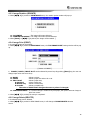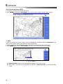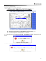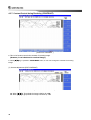
1
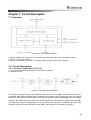
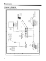
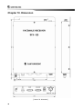
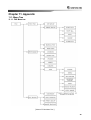
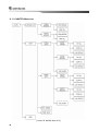
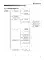
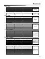
Weather Fax Receiver
Installation and
Operation Manual
MODEL : SFX-100
SAMYUNG ENC CO., LTD.
FIRST EDITION : 2008.04.23
Contents
SFX-100
Rev.1.0(080423)
Chapter 1. Overview ............................................................................................................. 3
1.1. Features ........................................................................................................ 3
1.2. Components .................................................................................................. 3
Chapter 2. Specification....................................................................................................... 4
2.1. General Specification .................................................................................... 4
Chapter 3. Description ......................................................................................................... 4
3.1. Connectors and Switches Description .......................................................... 4
3.2. LCD Screen Description................................................................................ 5
Chapter 4. FAX Mode............................................................................................................ 6
4.1. FAX Mode Selection...................................................................................... 6
4.2. FAX Reception (RCV FAX)............................................................................ 7
4.2.1. Reception Channel Setup (CH SETUP) ...................................... 7
4.2.2. Timer Setup (TIMER SETUP) ...................................................... 8
4.2.3. Manual Receiving (MANUAL RCV) ............................................. 9
4.2.4. Stop Receiving (STOP RCV) ....................................................... 9
4.3. View Image (VIEW IMAGE) .......................................................................... 9
4.3.1. Image Zoom In (ZOOM IN) ........................................................ 10
4.3.2. Image Zoom Out (ZOOM OUT) ................................................. 10
4.3.3. Image Rotation (RORATE) .........................................................11
4.3.4. Image Print (PRINT) ...................................................................11
4.3.5. Image Delete (DELETE) .............................................................11
4.3.6. Receiving Setup (EDIT) ............................................................. 12
4.3.7. Contrast Control during Receiving (CONTRAST) ..................... 16
4.4. Fax Setup (FAX SETUP)............................................................................. 17
4.4.1. Station Setup (EDIT STATION).................................................. 17
4.4.2. PRINT SETUP (PRINT SETUP) ................................................ 18
4.4.3. Image Backup (IMAGE BACKUP) ............................................. 18
Chapter 5. NAVTEX Mode .................................................................................................. 19
5.1. NAVTEX Mode Selection (NAVTEX)........................................................... 19
5.2. Message List (MESSAGE LIST) ................................................................. 19
5.2.1. 518KHz Messages..................................................................... 19
5.2.2. 490KHz Messages..................................................................... 19
5.3. Setting (SETUP) .......................................................................................... 20
5.3.1. 518KHz Setting (518KHz RCV SETUP) .................................... 20
5.3.2. 490KHz Setup (490KHz SETUP) .............................................. 22
5.3.3. Frequency Selection (RCV CHANNEL) Setup .......................... 22
5.3.4. Print Setup (PRINT SETUP) ...................................................... 22
5.4. Print ............................................................................................................. 22
Chapter 6. System Setting (SYSTEM SETUP).................................................................. 23
6.1. System Setup Selection .............................................................................. 23
6.2. Receiving Setup (RCV SETUP) .................................................................. 23
6.2.1. Receiving Mode Setting (RCV MODE) ...................................... 23
6.2.2. Receiving Alarm Setting (RCV NOTICE) ................................... 24
6.3. Time Setting (SET TIME)............................................................................. 24
6.4. Device Selection (DEVICE)......................................................................... 24
6.4.1. Input Device (KEYBOARD) ....................................................... 25
6.4.2. Appointed Printer by a User (USER PRINTER) ........................ 25
6.5. System Test (TEST MODE)......................................................................... 27
6.5.1. System Version (SYSTEM VERSION) ...................................... 27
6.5.2. Test Print (PRINT TEST)............................................................ 28
6.5.3. Buzzer Test (BUZZER TEST) .................................................... 28
6.5.4. Self Test (SELF TEST)............................................................... 29
6.6. Initialization (CLEAR SETUP) ..................................................................... 30
6.6.1. Memory Delete (CLEAR MEMORY) .......................................... 30
6.6.2. Load Default (LOAD DEFAULT) ................................................ 30
6.6.3. Software Upgrade (SW UPGRADE) Setup ............................... 31
6.7. Simulation (SIMULATION) .......................................................................... 32
6.7.1. Fax Simulation (FAX SIMULATION) .......................................... 32
1
Chapter 7. Circuit Description........................................................................................... 33
7.1. Overview...................................................................................................... 33
7.2. Circuit Description ....................................................................................... 33
7.2.1. Receiver / Synthezier ( P101212 )............................................. 33
Chapter 8. TROUBLESHOOTING ...................................................................................... 35
8.1. Overview...................................................................................................... 35
8.2. Measuring Instrument.................................................................................. 35
8.3. SFX-100 Inspection and Maintenance ........................................................ 35
8.3.1. Antenna...................................................................................... 35
8.3.2. Power ......................................................................................... 35
8.3.3. Receiver ..................................................................................... 35
Chapter 9. Diagram............................................................................................................. 36
9.1. Connection Diagram.................................................................................... 36
9.2. Wiring Diagram............................................................................................ 37
Chapter 10. Dimension....................................................................................................... 38
Chapter 11. Appendix ......................................................................................................... 39
11.1. Menu Tree.................................................................................................. 39
11.1.1. FAX Menu tree ......................................................................... 39
11.1.2. NAVTEX Menu tree .................................................................. 40
11.1.3. SYSTEM SETUP Menu tree .................................................... 41
11.2. World Major Weather Fax Frequency........................................................ 42
11.2.1. ASIA ......................................................................................... 42
11.2.2. SOUTH AMERICA ................................................................... 44
11.2.3. NORTH AMERICA ................................................................... 44
11.2.4. PACIFIC OCEAN BASIN.......................................................... 45
11.2.5. EUROPE .................................................................................. 46
11.2.6. AFRICA .................................................................................... 47
2
Chapter 1. Overview
1.1. Features
The SFX-100 weather fax receiver can receive
weather fax image and NAVTEX message with
directly connected LCD monitor, printer and
keyboard.
(1) General Control
The SFX-100 weather fax receiver is integrated by
major circuits such as a controller, a power supply, a
synthesizer and others for ideal the integrated
control of each device’s functions.
(2) Compatibility
The SFX-100 has compatibility with your existing
LCD monitor, keyboard and printer. The receiver is
controlled by the keyboard and can be monitored by
the monitor.
(3) Can store up to twenty (20) image data.
(4) Can select a stored image in simple screen mode.
(5) Receive weather information which is suited to
WMO standard from a weather information center
(6) Both automatic and manual synchronization are
supported
(7) Automatic receives channel setup help to receive
optimized super fine data.
(8) NAVTEX reception can be stored up to 115 text
messages of maximum 16,000 characters per
channel.
1.2. Components
The SFX-100 is consisting of basic, optional components and supplements provided by a user. Also each
device is consist of PCB based on functions.
(1)
(2)
ITEM
Weather Fax Receiver
Receiver and Synthesizer
Controller and Power Supply
(1)
Remote Controller
Spare Parts, installation
Materials
Power Cable
(2)
(3)
No.
1
2
3
4
MODEL
SFX-100
P101212-0X
P101281-0X
KEYPAD USB
NORMAL KEYS
Q’TY
1SET
1
1
NOTE
1
1SET
SCN3-3M-D3
1
Fix Screw
Stainless Screw
1 Type 4X16mm
4
Fuse
User’s Manual and
Installation Drawing
2A, L=20mm
2
1
[ Table 1. Basic Components ]
ITEM
No.
1
(1)
(2)
2
(1)
(2)
3
4
WHIP ANT SET
WHIP ANT
M-TYPE CONNECTOR
WIRE ANT SET
CABLE
JOINT BOX
COAXIAL CABLE
POWER SUPPLY
MODEL
DAF30R
P101281-0X
565-0109-01
SA-300
BNCP-20M-RG58
SP-300AD
Q’TY
1SET
1
1
1SET
15m
1
1
1
NOTE
20m
[ Table 2. Optional Components ]
No.
1
2
ITEM
MONITOR (LCD)
Keyboard
3
PRINTER
MODEL
PC/AT 101 Keyboard(USB)
HP Inkjet, HP Deskjet.
HP Lazerjet, HP officejet
Q’TY
1
1
1
NOTE
Support printers only Which
PCL3 is supported by standard
printer language
[ Table 3. User’s Supplements ]
3
Chapter 2. Specification
2.1. General Specification
Frequency
: FAX 0.5MHz – 25MHz
NAVTEX 490KHz/518KHz
Frequency Stability : SYNTHESIZER Type,
Declination within 10 (Within 0.3ppm)
Storable CH
: 320CH
(A number of channel that a user can store)
Store Capacity
: FAX(20 PICTURE)
NAVTEX (Max.16,000Characters’ 115text message
per CH.)
Modulation Type : FAX(F3C/J3C), NAVTEX(F1B)
Receiving Type : Double superheterodync.
Interface
: Monitor (LCD),
Remote Controller (Keyboard), Printer
Display Color : Black and Yellow,
Green and Black, and Black and Gray.
Power : Rated DC 12V~24V (-10% ~ +20%), 1A
Antenna
: WHIP Antenna (DAF30R)
Or WIRE Antenna 15M
Dimension
: 203(W) X 290(L) X 43(H)
Weight
: 2Kg㎏
Chapter 3. Description
3.1. Connectors and Switches Description
① Grounding : System grounding.
② ANT : Connect WHIP
or WIRE antenna.
③ DATA : Being used for software
upgrade.
④ RGB-OUT :
Connect LCD monitor.
⑤ USB :
External interface connector
which connect a printer and
keyboard.
⑥ PWR : Supply DC 12V ~ 24V.
⑦ Power Switch :
The power switch of SFX- 100.
⑧ Fuse : 2A Fuse
4
3.2. LCD Screen Description
(1) Basic Specification
The resolution of LCD is set to 800 X 600. (Default)
Screen Display
Function
Display
Status Display
[ Picture 1. LCD Screen ]
(2) Screen Display
A fax image will be displayed in fax mode or a received message will be displayed in NAVTEX mode.
(3) Function Display
There is a description of function Key.
a)
To choose Function, hit appropriate key while pushing [
] key in key pad.
If it is PC/AT 101 keyboard, hit an assigned function key.
(Example) To select [ FAX ] at above screen,
Key Pad : Hit [1] while pushing [
].
PC/AT 101 Keyboard : Hit [F1].
b) The LED indicator of [NumLock] has to be ON to input numbers and has to be OFF to use arrow keys and
for other functions.
(4) Status Display
It displays current status such as frequency, mode, date, time, etc.
5
Chapter 4. FAX Mode
4.1. FAX Mode Selection
(1) When power is supplied, following screen will Show up.
[ Picture 2. Top Menu ]
(2) When [
]
[ 1 ] is pushed at top menu, it will enter into ’FAX MODE’.
[Picture 3. FAX MODE ]
(3) An arrow key allows a user to select image and when [ENTER] or [
]
[ 2 ] key is pushed image will be
displayed.
6
4.2. FAX Reception (RCV FAX)
In FAX MODE, it will change to Fax reception (RCV FAX) when [
]
[ 1 ] key is pushed.
[ Picture 4. RCV FAX ]
4.2.1. Reception Channel Setup (CH SETUP)
This SETUP allows a user to choose a transmitting station and a channel to receive messages automatically.
In RCV FAX menu, the channel setup window will pop up when [
]
[ 1 ] is pushed.
[ 그림 5. CH SETUP ]
‘ZONE/STATION/SPEED/FREQUENCY’ can be selected by arrow keys. By pushing [Enter] key, the
user can change input value with arrow keys.
ZONE
: Select current location.
STATION
: Select a station to receive weather fax broadcasting.
CHANNEL : Select the frequency of selected station
(When AUOT is selected, the frequency will be scanned automatically)
IOC
: The standard of line density assigned by WMO.
(When AUTO is selected, it will be assigned automatically)
SPEED(RPM) : A number of line can be received during receiving a broadcasting.
(When AUTO is selected, it will assigned automatically)
FREQUENCY : A frequency can be changed during manual receiving.
(When AUTO is selected, no input)
※ The LED indicator of [NumLock] has to be ON to input numbers and has to be OFF to use arrow keys and
for other functions.
When [][ 7 ] is pushed, channel selection is completed.
7
4.2.2. Timer Setup (TIMER SETUP)
A user can set receiving time, transmitting station and frequency.
When [
]
[ 2 ] is pushed in RCV FAX menu, it will switch to ‘TIMER SETUP’ screen.
[ 그림 6. TIMER SETUP ]
(1)
(2)
(3)
(4)
By pushing arrow
When [
]
[ 1 ]
When [
]
[ 2 ]
When [
]
[ 3 ]
key, a timer list can be selected.
is pushed in ‘TIMER SETUP’ menu, it STRAT ALL timer lists that is set to ‘ON’
is pushed in ‘TIMER SETUP’ menu, it STOPS ALL timer lists that is set to ‘OFF’.
is pushed in ‘TIMER SETUP’ menu, The ‘EDIT TIMER’ window will pop up.
[ Picture 7. EDIT ]
‘ZONE/STATION/SPEED/FREQUENCY’ can be selected by arrow keys. By pushing [Enter] key, the
user can change input value with arrow keys.
‘ZONE / STATION / CHANNEL / IOC / SPEED / ON or OFF / FREQUENCY / START TIME / END
TIME' can be selected by arrow keys. By pushing [Enter] key, the user can change input value with arrow
keys.
When [
]
[ 7 ] is pushed the timer setting is completed.
(5) When [
]
[ 4 ] is pushed in ‘TIMER SETUP’ menu, a currently selected list will be deleted.
(6) When [
]
[ 4 ] is pushed in ‘TIMER SETUP’ menu, all programmed timer lists will be deleted.
8
4.2.3. Manual Receiving (MANUAL RCV)
Weather fax can be received in manual mode
SET UP a channel in [CH SETUP]
When [
]
[ 3 ] is pushed in RCV FAX menu, it will display ‘MANUALSTART RCV’
[ Picture 8. MANUAL RCV ]
Select desirable IOC/RPM.
When [Enter] or [
]
[ 7 ] is pushed, the manual receiving will be started.
4.2.4. Stop Receiving (STOP RCV)
A whether fax broadcasting can be stopped when receiving. .
When [
]
[ 4 ] is pushed in RCV FAX menu, a massage receiving will be cancelled.
4.3. View Image (VIEW IMAGE)
When [
]
[ 2 ] is pushed in fax mode, the screen will be changed to ‘VIEW IMAGE’.
[ Picture
9. VIEW IMAGE ]
9
4.3.1. Image Zoom In (ZOOM IN)
When [
]
[ 1 ] is pushed in VIEW IMAGE menu, the selected image will be enlarged.
[ Picture 10. ZOOM IN ]
4.3.2. Image Zoom Out (ZOOM OUT)
When [
]
[ 2 ] is pushed in VIEW IMAGE menu, the size of selected image will be decreased.
[ Picture 11. ZOOM OUT ]
10
4.3.3. Image Rotation (RORATE)
When [
]
[ 3 ] is pushed in VIEW IMAGE menu, the rotation option window will pop up.
[Picture 12. ROTATE ]
CLOCKWISE
: The image will rotate clockwise.
COUNTERCLOCKWISE : The image will rotate counterclockwise.
When [Enter] or [
]
[ 7 ] is pushed, the image will be rotated. [
4.3.4. Image Print (PRINT)
A received Image can be printed.
When [
]
[ 4 ] is pushed in VIEW IMAGE menu, the ‘FAX IMAGE PRINT’ setting window will be pop
up.
[ Picture 13. PRINT ]
‘MODEL / PAPER / INPUT SLOT’ can be selected by arrow keys. By pushing [Enter] key, the user can
change input value with arrow keys.
MODEL
: Select a printer.
PAPER
: Select a paper size either A3 or A4.
INPUT SLOT
: Select a paper tray.
Standard
: select a basic tray.
Manual tray
: Select a manual tray.
Portable
: Select a portable tray.
※ The value of INPUT SLOT changes whenever a printer is changed.
CENTERING IMAGE : If a received image is smaller than print paper, this option allows an image to
print from center.
When [
]
[ 7 ] is pushed, the setup is completed.
4.3.5. Image Delete (DELETE)
A selected image can be deleted.
When [
]
[ 5 ] is pushed in VIEW IMAGE menu, it will change to IMAGE DELETE selection
screen.
11
4.3.6. Receiving Setup (EDIT)
The phase, sync and screen display can be set.
When [
]
[ 6 ] is pushed in VIEW IMAGE menu, it will change to image reception setting screen.
[ Picture 14. EDIT IMAGE ]
(1) Phase
When the weather fax receive a image, it can be separated with a thin black line called ‘Dead Sector’ by a
noise protect detection phase signal caused by phase mismatching.
If this is happening, the broadcasting can be completed by correcting the phase mismatching.
When [
]
[ 1 ] is pushed in EDIT IMAGE menu, the phase window will pop up for setting.
[ 그림 15. PHASE ]
‘DEAD SECTOR’s location can be adjusted by graduation on the top of screen
Setting Value : The value can be set between 0 ~ 50 and the DEAD SECTOR is moved by the setting
value.
12
(2) Synchronization (SYNC)
This is the function that tunes phase signal. If the DEAD SECOTR is tilted, it can be corrected by changing a
setting value.
When [
]
[ 2 ] is pushed in EDIT IMAGE menu, it will change to ‘EDIT SYNC’ screen.
[ Picture 16. SYNC ]
LEFT : When [
]
[ 1 ] is pushed, Can adjust a tilt to left side
RIGHT : When [
]
[ 2 ] is pushed, Can adjust a tilt to right side
(3) Color Setup (SET COLOR)
The screen color can be set
When [
]
[ 3 ] is pushed in EDIT IMAGE menu, the ‘EDIT COLOR’ window will pop up.
[ Picture 17. SET COLOR ]
MONOCHROME :
GRAY SCALE
:
YELLOW-BLACK :
GREEN-BLACK :
Display in black and white.
Display in gray
Display in yellow and black.
Display in green and black.
When [Enter] or [
]
[ 7 ] is pushed, the printer setting is completed.
(4) Screen Color Reverse (REVERSE COLOR)
When [
]
[ 4 ] is pushed in EDIT IMAGE menu, the display color will display in reverse.
13
(5) Image Automatic Delete Lock (LOCK)
A received image can be prevented form deleting.
When [
]
[ 5 ] is pushed in EDIT IMAGE menu, ‘FAX IMAGE LOCK’ window will pop up
[ Picture 18. LOCK-1 ]
If it is set to ’ON’, it will be never deleted.
If a image is Locked, a lock icon ( ) will be displayed on the top of screen.
[ Picture 19. LOCK-2 ]
(6) Noise Elimination (NOISE REJECT)
When [
]
[ 6 ] is pushed in EDIT IMAGE menu, ‘NOISE REJECT’ screen will be displayed.
[ Picture 20. NOISE REJECT ]
If there is noise on received image. Select ‘NOISE REJECT’ to ON to eliminate the noise.
14
(7) Image Copy (COPY IMAGE)
Received images can be stored in USB MEMORY.
When [
]
[ 7 ] is pushed in EDIT IMAGE, ‘COPY IMAGE’ window will pop up.
※ Before saving a image, a USB memory has to be plugged in USB slot.
[ Picture 21. COPY IMAGE ]
When the key pad is used, only numbers can be inputted for file name.
When PC/AT 101 keyboard is used, mixed alphabets and numbers can be used.
It will saved in gif format even though there is no extension.
If USB a USB memory is not plugged when [
]
[ 7 ] is pushed in COPY IMAGE, following window will
pop up.
[ Picture 22. Can’t find USB memory ]
If there is not enough space in USB memory, following window will pop up.
[ Picture 23. Can’t get enough space USB memory ]
15
4.3.7. Contrast Control during Receiving (CONTRAST)
[ Picture 24. CONTRAST ]
This is the function controls the contrast of incoming image.
(However, it can’t be done for received image)
When [
]
[ 7 ] is pushed in VIEW IMAGE menu, a user can change the contrast of incoming
image.
(1) Contrast Adjustment (EDIT CONTRAST)
[ Picture 25. EDIT CONTRAST ]
When [
]
[ 1 ] is pushed the image is darker by +10.
When [
]
[ 2 ] is pushed the image is dimmer by -10.
16
4.4. Fax Setup (FAX SETUP)
When [
]
[ 3 ] is pushed in FAX MODE, a user can change the ‘FAX SETUP’.
[ Picture 26. FAX SETUP ]
4.4.1. Station Setup (EDIT STATION)
A user can add and edit a desired station.
When [
]
[ 1 ] is pushed in FAX SETUP menu, the ‘EDIT STATION’ windows will pop up.
[ Picture 27. EDIT STATION ]
17
4.4.2. PRINT SETUP (PRINT SETUP)
When [
]
[ 2 ] is pushed in FAX SETUP menu, the ‘FAX PRINT SETUP’ window will pop up.
[ Picture 28. PRINT SETUP ]
If the mode of printer is set to AUTO, it will print out the received image after receiving image.
If the mode is set to MANUAL, a user can select an image which needs to be printed out..
4.4.3. Image Backup (IMAGE BACKUP)
When [
]
[ 3 ] is pushed in FAX SETUP menu, the ‘FAX IMAGE BACKUP’ screen will pop up.
[ Picture 29. IMAGE BACKUP ]
If it is set to AUTO, images will be saved in USB Memory, flash memory.
If it is set to MANUAL, selected received images can be saved.
18
Chapter 5. NAVTEX Mode
5.1. NAVTEX Mode Selection (NAVTEX)
When [
]
[ 2 ] is pushed in the top menu, it will enter into ‘NAVTEX MODE’.
[Picture 30. NAVTEX MODE ]
5.2. Message List (MESSAGE LIST)
When [
]
[ 1 ] is pushed in NAVTEX mode, the screen will change to MESSAGE LIST.
[Picture 31. MESSAGE LIST ]
5.2.1. 518KHz Messages
Messages received in 518KHz can be printed out, checked and aligned.
When [
]
[ 1 ] is pushed in MESSAGE LIST, 518KHz MESSAGE menu will pop up
[Picture 32. 518KHz MESSAGE ]
(1) Message View (VIEW MESSAGE)
When [
]
[ 1 ] is pushed, a selected message can be checked.
(2) Print All Received Messages (PRINT ALL)
When [
]
[ 2 ] is pushed, All received messages can be printed out.
5.2.2. 490KHz Messages
Same as ‘5.2.1. 518KHz message (518KHz MESSAGES)’.
19
5.3. Setting (SETUP)
When [
]
[ 2 ] is pushing in NAVTEX mode, it will enter into ‘NAVTEX SETUP’ screen.
[ Picture 33. SETUP ]
5.3.1. 518KHz Setting (518KHz RCV SETUP)
518 station can be set manually.
When [
]
[ 1 ] is pushed in SETUP menu it will change to ‘518KHz RCV SETUP’ screen.
[ Picture 34. 518KHz SETUP ]
20
(1) Station Selection (SELECT STATION)
When [
]
[ 1 ] is pushed in 518KHz RCV SETUP menu, a station can be selected manually.
[ Picture 35. SELECT STATION ]
SET ALL
: All stations can be selected by pushing [
]
[ 1 ]
CLEAR ALL
: The selection of all station can be cancelled by pushing
LOAD DEFAULT : Default value can be set by pushing [
]
[ 3 ].
(2) Message Selection (SELECT MESSAGE) Setting
When [
]
[ 2 ] is pushed in 518KHz RCV SETUP menu, a message can be selected manually.
[ Picture 36. SELECT MESSAGE ]
It is same as the selection of station..‘(1) Station Selection (SELECT STATION)’
(3) A.B.L alarm (A.B.L ALARM) Setting
When [
]
[ 3 ] is pushed in 518KHz RCV SETUP menu, the A.B.L alarm setting window will pop
[ Picture 37. A.B.L ALARM ]
21
5.3.2. 490KHz Setup (490KHz SETUP)
When [
]
[ 2 ] is pushed in SETUP menu, the 490 setting window will pop up.
The setup is same as 518 setting. ‘5.3.1. 518KHz Setting (518KHz RCV SETUP)’
5.3.3. Frequency Selection (RCV CHANNEL) Setup
When [
]
[ 3 ] is pushed in SETUP menu, the screen will change as below.
[ Picture 38. RCV CHANNEL ]
5.3.4. Print Setup (PRINT SETUP)
When [
]
[ 4 ] is pushed in SETUP menu, the screen will change as below.
[ Picture 39. PRINT SETUP ]
If the printer is set to auto, it will print out any received message AUTOmatically and if it is set to
MANUAL, a user can print out a selected message.
5.4. Print
When [
]
[ 3 ] is pushed, the message which is displaying on the screen can be print out.
[ Picture 40. PRINT ]
‘MODEL / PAPER / INPUT SLOT’ can be selected by arrow keys. By pushing [Enter] key, the user can
change input value with arrow keys.
MODEL
: Select a printer.
PAPER
: Select a paper size either A3 or A4.
INPUT SLOT
: Select a paper tray.
Standard
: select a basic tray.
Manual tray
: Select a manual tray.
Portable
: Select a portable tray.
※ The value of INPUT SLOT changes whenever a printer is changed.
When [
]
[ 7 ] is pushed, the setup is completed.
22
Chapter 6. System Setting (SYSTEM SETUP)
6.1. System Setup Selection
When [
]
[ 3 ] is pushed in top menu, it will enter into ‘SYSTEM SETUP’ menu.
[ Picture 41. SYSTEM SETUP ]
6.2. Receiving Setup (RCV SETUP)
When [
]
[ 1 ] is pushed in system setting menu, the mode will change to ‘SYSTEM RECEIVING
SETUP’ screen.
[ Picture 42. RCV SETUP ]
6.2.1. Receiving Mode Setting (RCV MODE)
This is function that allows a user to choose whether to receive weather fax image or NAVTEX or both.
When [
]
[ 1 ] is pushed in RCV SETUP menu, the receiving mode(RCV MODE) window will pop
up.
[ Picture 43. RCV MODE ]
FAX ONLY
: Receive only weather fax messages.
NAVTEX ONLY : Receive only NAVTEX messages.
FAX(TIMER MODE) & NAVTEX : Receive set images or NAVTEX messages by timer.
23
6.2.2. Receiving Alarm Setting (RCV NOTICE)
This is the function that give a choice to user to chose that weather fax image and NAVTEX message
receiving with alarm or not.
When [
]
[ 2 ] is pushed in SPEAKER menu, it will change to receiving alarm setting(SPEAKER) screen.
[ Picture 44. SPEAKER ]
When ‘ON’ is selected, there is an alarm when it receives a message.
When ‘OFF’ is selected, there is no alarm when it receives a message.
6.3. Time Setting (SET TIME)
This function allows a user to set a time.
When [
]
[ 2 ] is pushed in system setting menu, the ‘SET DATE & TIME’ window will pop up.
[ Picture 45. SET TIME ]
6.4. Device Selection (DEVICE)
A user can select an input device in this option. .
When [
]
[ 3 ] is pushed in system setting menu, it will switch to device selection(DEVICE) window.
[ Picture 46. DEVICE ]
When [
]
[ 1 ] is pushed, it will switch to input device selection window.
When [
]
[ 2 ] is pushed, the screen will change to printer selection screen.
24
6.4.1. Input Device (KEYBOARD)
[ Picture 47. KEYBOARD ]
NUMERIC KEYPAD : Input can be done by numeric keypad..
(Function Key : Display in ‘number’)
KEYBOARD
: Input can be done by PC/AT 101 keyboard.
(Function Key : Display in ‘F number’)
6.4.2. Appointed Printer by a User (USER PRINTER)
[ Picture 48. USER PRINTER ]
(1) ADD Printer (ADD PRINTER)
Additional Printers can be added beside of a provided printer.
When [
]
[ 1 ] is pushed in USER PRINTER menu, the screen will pop up the ‘ADD PRINTER’ window.
MODEL NAME : A user can name an added
printer. Select an alphabet by arrow keys and
input the alphabet by Enter Key.
MODEL TYPE : Select the type of printer.
When [Enter] key is
pushed, a user can select a
printer
among
‘LASERJET, DESKJET, OFFICEJET’
RESOLUTION : The resolution of priter can be
selected. When [Enter] key is pushed, a user
can select the resolution among ‘150 DPI, 300
DPI, 600 DPI’ and over.
PAPER SIZE
or A4.
: Paper can be selected either A3
PAPER SOURCE : A printer tray can be selected.
[ Picture 49. ADD PRINTER ]
25
(2) Printer Edit (EDIT PRINTER)
The setting of added printer can be modified.
When [
]
[ 2 ] is pushed in USER PRINTER menu, ‘EDIT PRINTER’ will pop up.
[ Picture 50. EDIT PRINTER ]
(3) Printer Delete (DELETE PRINTER)
An Added printer can be deleted. .
when [
]
[ 3 ] is pushed in USER PRINTER menu, ‘DELETE PRINTER’ window will pop up.
[ Picture 51. DELETE PRINTER ]
26
6.5. System Test (TEST MODE)
When [
]
[ 4 ] is pushed in SYSTEM SETUP menu, the screen will change to system ‘TEST MODE’
screen.
[ Picture 52. TEST MODE ]
6.5.1. System Version (SYSTEM VERSION)
This is the function that allows a user to check the system version.
When [
]
[ 1 ] is pushed in self diagnostic menu(SYSTEM VERSION), the system version window will
pop up.
[ Picture 53. SYSTEM VERSION ]
27
6.5.2. Test Print (PRINT TEST)
When [
]
[ 2 ] is pushed in self diagnostic menu, the ‘PRINT TEST’ window will pop up.
[ Picture 54. PRINT TEST ]
Select a printer model, paper size and a tray by arrow keys.
When [
]
[ 7 ] is pushed, the printer will start printing for test.
[ Picture 55. PRINT TEST COMPLETION ]
When [
]
[ 7 ] is pushed, the following message will pop up if a printer is not connected.
[ Picture 56. Printer Connection Bad ]
6.5.3. Buzzer Test (BUZZER TEST)
When [
]
[ 3 ] is pushed in self diagnostic menu, the test buzzer(BUZZER TEST) window will pop up.
[ Picture 57. BUZZER TEST ]
28
6.5.4. Self Test (SELF TEST)
System status can be checked in this menu.
When [
]
[ 4 ] is pushed in self test mode, the SYSTEM ‘SEL-TEST’ window will pop up and perform the
self test.
[ Picture 58. SELF TEST ]
MEMORY TEST : Test the cup and memory of device.
RF TEST
: Test the from input of antenna to the input of CPU
When [
]
[ 7 ] is pushed, the SYSTM SELF-TEST window will pop up and start the diagnostic. If there
is no problem, following message will pop up.
[ Picture 59. Self Diagnostic Completion ]
If there is any problem, following message will pop up.
[ Picture 60. Display of Error ]
[ Picture 61. Self Diagnostic Error ]
29
6.6. Initialization (CLEAR SETUP)
When [
]
[ 5 ] is pushed in system setting menu, the screen will change to ‘CLEAR SETUP’.
[ Picture 62. CLEAR SETUP ]
6.6.1. Memory Delete (CLEAR MEMORY)
When [
]
[ 1 ] is pushed in the factory setting menu, the ‘CLEAR MEMORY’ window will pop up.
[ Picture 63. CLEAR MEMORY ]
FAX IMAGE
: Delete all received weather fax images.
NAVTEX MESSAGE : Delete all received NAVTEX message.
USER SETUP DATA : Delete all changed value by a user, weather fax images and NAVTEX images
(FACTORY SETUP)
6.6.2. Load Default (LOAD DEFAULT)
When [
]
[ 2 ] is pushed in initialization menu, the ‘LOAD DEFAULT SETUP’ window will pop up.
[ Picture 64. LOAD DEFAULT ]
30
6.6.3. Software Upgrade (SW UPGRADE) Setup
When [
]
[ 3 ] is pushed in initializing setup menu, the software can be upgraded.
[ Picture 65. S/W UPGRADE ]
When [
]
[ 7 ] is pushed, following window which is asking the software upgrade with USB memory will
pop up.
[ Picture 66. SW UPGRADE-1 ]
The software upgrade can be checked with following pop up window.
[ Picture 67. SW UPGRADE-2 ]
31
6.7. Simulation (SIMULATION)
When [
]
[ 6 ] is pushed in system setup menu, the will switch to ‘SIMULATION MODE’.
[ Picture 68. SIMULATION MODE ]
6.7.1. Fax Simulation (FAX SIMULATION)
When [
]
[ 1 ] is pushed in simulation mode, the ‘FAX SIMULATION’ window will pop up.
[ Picture 69. FAX SIMULATION ]
ON : Delete all received images and the simulation will run once.
OFF : It will not run simulation.
32
Chapter 7. Circuit Description
7.1. Overview
[ Picture 70. SFX-100 Block Diagram ]
SFX-100 weather fax receiver can be connected with a keyboard and a printer with USB connector.
DC12V ~ 24V Can be supplied.
SFX-100 is consisting of a receiver, a synthezier board, a power supply and a controller.
7.2. Circuit Description
7.2.1. Receiver / Synthezier ( P101212 )
T-1140 Circuit board can be divided into receiver and synthezier.
(1) Reception Circuit
[ Picture 71. Reception Block Diagram ]
The type of receiving is double super heterodyne which uses 1'st IF=49.455㎒, 2'nd IF=455㎑ frequencies.
Received signal through antenna will be amplified at RF amplifier (Q13) through BPF. Once the signal is
amplified, it will mix with 1’st local frequency at first mixer (MX1) and will be demodulated to be a first middle
frequency. The middle frequency will mix with second local frequency at second mixer(MX2) through 49.455㎒
X-tal filter(XL2,3) and IF amplifier(Q20) and it will become FSK signal after modulation with BFO (Beat
Frequency OSC) at the third mixer(IC7) through 455㎑ X-tal filter(XL1)와 IF amplifier (Q17,Q23)
33
(2) Local Synthesizer Circuit
[ Picture 72. Synthesizer Block Diagram ]
The standard frequency based on the output of14MHz OCXO (Over Compensated X-tal Oscillator) consists a
PPL circuit and outputs the first local frequency, 49.455~79.454MHz. The standard frequency , 14MHz is
divided into 2(two) and multiplied by 7(seven) to use for 49MHz second Local. The third local frequency which
is BFO(Beat Frequency Oscillator) generates 456.9kHz signal at DDS(DM1)
(3) Power Circuit
[ Picture 73. Power Block Diagram ]
: The power circuit receives DC12~24V and supplies +10.8V~22.8V through a
protection and regulated voltage circuit.
Main Power Circuit : When the power switch is ON, VDD(+9) and VCC_ANA(+5V) will be supplied to
analog circuit through a switching regulator circuit and a voltage IC. Also,
VCC_D(+5V) is supplied to digital circuit and the voltage is supplied +1.2V through
0.8A regulator and +3.3V through 3A regulator.
Protection and Sensor Circuit : The protection and sensor circuit which equips a voltage sensor circuit
prevents a power off automatically under +12V and above +24V. It also equips with
reverse voltage protection circuit to protect from reverse voltage supply.
34
The power circuit
Chapter 8. TROUBLESHOOTING
8.1. Overview
The most of reason which causes trouble is related to mechanical and electrical reasons in the internal and
external of device and these reasons can be prevented by periodical inspection and maintenances. Also this
device equips with all kid of protection circuit to protect circuits and parts. However, if there are any troubles
that caused a difficulty to operate then it needs to be repaired in fast and rational manner. To maintain its
original performance and life expectancy, periodical inspection and maintenance is required. Please be aware
of matters to be attended as below before inspection and maintenance to avoid improper maintenances.
8.2. Measuring Instrument
This device is designed accordingly to international wireless communication laws and measuring
instruments for inspection and maintenance is needed to be inspected and tested by an authorized agency.
For daily inspection and maintenance, following measuring instruments are needed.
Measuring Instrument for inspection and repair
1
A multi meter for the measurement of resistor, voltage and current
2
A frequency Counter that can measure 100MHz bandwidth
3
An oscilloscope that can measure 100MHz bandwidth
4
A Signal generator that can measure 100MHz bandwidth
5
Others
[ Table 4. The list of measuring instruments for inspection and repair ]
8.3. SFX-100 Inspection and Maintenance
8.3.1. Antenna
If there is difficulty in communication caused by noise, signal reception and so on, check an antenna first
whether there is any defection or not and then check followings.
(1) Whether a whip antenna is properly connected.
(2) Whether metallic object is near an antenna or not.
(3) Whether the connection and insulation between an antenna and receiver is proper or not.
8.3.2. Power
If there is no display even though the power is on, following are needed to be checked.
(1) Whether fuse is disconnected or not (The rated current of fuse is 2A)
(2) Whether the power connector is properly connected or not. (If the polarity of power is opposite, the device
will not work)
(3) Check the voltage in the power supply connector. (if it is between DC 12~24V, it is normal.)
8.3.3. Receiver
Make sure all interface devices are properly connected.
(1) Check an antenna.
(2) Check P101212 PC in device and replace with one if the board is defected.
35
Chapter 9. Diagram
9.1. Connection Diagram
[ Picture 74. SFX-100 Device Connection Diagram ]
36
9.2. Wiring Diagram
[ Picture 75. SFX-100 Wiring Diagram ]
37
Chapter 10. Dimension
[ Picture 76. Dimension ]
38
Chapter 11. Appendix
11.1. Menu Tree
11.1.1. FAX Menu tree
[ Picture 77. Fax Menu Tree ]
39
11.1.2. NAVTEX Menu tree
[ Picture 78. NAVTEX Menu Tree ]
40
11.1.3. SYSTEM SETUP Menu tree
[ Picture 79. System Setup Menu Tree ]
41
11.2. World Major Weather Fax Frequency
[ Picture 80. World Map ]
11.2.1. ASIA
Republic of Korea - SEOUL
CALL SIGNS
HLL2
HLL2
HLL2
HLL2
HLL2
5385 kHz
5857.5 kHz
7433.5 kHz
9165 kHz
13570 kHz
TIMES
ALL
ALL
ALL
ALL
ALL
BROADCAST
BROADCAST
BROADCAST
BROADCAST
BROADCAST
China - BEIJING
CALL SIGNS
BAF6
BAF36
BAF4
BAF8
BAF9
BAF33
FREQUENCIES
5526.9 kHz
8121.9 kHz
10116.9 kHz
14366.9 kHz
16025.9 kHz
18236.9 kHz
TIMES
China - BEIJING
CALL SIGNS
FREQUENCIES
TIMES
3SD
3SD
3SD
42
FREQUENCIES
8461.9 kHz
12831.9 kHz
16903.9 kHz
RPM / IOC
TIMES
TIMES
TIMES
TIMES
TIMES
120/576
RPM / IOC
120/576
RPM / IOC
120/576
Japan - TOKYO
CALL SIGNS
JMH
JMH2
JMH4
Chukotka Peninsula - PEVEK
CALL SIGNS
FREQUENCIES
3622.5 kHz
7795 kHz
13988.5 kHz
FREQUENCIES
148 kHz
Taiwan - TAIPEI
CALL SIGNS
BMF
Thailand - BANGKOK
CALL SIGNS
BMF
Uzbekistan - TASHKENT 1
CALL SIGNS
RBV70
RPJ78
RBV78
RBX72
RCH72
RBV76
Uzbekistan - TASHKENT 2
CALL SIGNS
RBX70
RBX71
RIJ75
RCH73
ROM5
FREQUENCIES
4616
5250
8140
13900
18560
RPM / IOC
ALL BROADCAST TIMES
ALL BROADCAST TIMES
ALL BROADCAST TIMES
120/576
TIMES
RPM / IOC
ALL BROADCAST TIMES
90/576
TIMES
RPM / IOC
kHz
kHz
kHz
kHz
kHz
FREQUENCIES
4616
5250
8140
13900
18560
120/576
TIMES
kHz
kHz
kHz
kHz
kHz
RPM / IOC
120/576
FREQUENCIES
TIMES
RPM / IOC
3690
4365
5890
7570
9340
14982.5
1300-0130
ALL BROADCAST TIMES
ALL BROADCAST TIMES
0130-1300
ALL BROADCAST TIMES
ALL BROADCAST TIMES
Can be changed
depending on a
broadcasting time
TIMES
RPM / IOC
ALL BROADCAST TIMES
ALL BROADCAST TIMES
1400-0200
ALL BROADCAST TIMES
0200-1400
Can be changed
depending on a
broadcasting time
TIMES
RPM / IOC
ALL BROADCAST TIMES
ALL BROADCAST TIMES
ALL BROADCAST TIMES
ALL BROADCAST TIMES
ALL BROADCAST TIMES
ALL BROADCAST TIMES
0740-1010, 1415-1815
0740-1010, 1415-1815
Can be changed
depending on a
broadcasting time
kHz
kHz
kHz
kHz
kHz
kHz
FREQUENCIES
3280
5285
8083
9150
13947
kHz
kHz
kHz
kHz
kHz
Japan/Singapore - KYODO NEWS AGENCY
CALL SIGNS
FREQUENCIES
JJC
JJC
JJC
JJC
JJC
JJC
9VF/252
9VF/252
TIMES
4316
8467.5
12745.5
16971
17069.6
22542
16035
17430
kHz
kHz
kHz
kHz
kHz
kHz
kHz
kHz
43
Great British (Persian Gulf) - NORTHWOOD
CALL SIGNS
FREQUENCIES
GYA
GYA
GYA
6834 kHz
12390 kHz
18261 kHz
TIMES
RPM / IOC
1800-0800 UTC
ALL BROADCAST TIMES
0800-1800 UTC
120/576
TIMES
RPM / IOC
ALL BROADCAST TIMES
ALL BROADCAST TIMES
120/576
TIMES
RPM / IOC
ALL BROADCAST TIMES
ALL BROADCAST TIMES
ALL BROADCAST TIMES
120/576
TIMES
RPM / IOC
11.2.2. SOUTH AMERICA
Brazil - RIO DE JANEIRO
CALL SIGNS
PWZ-33
PWZ-33
FREQUENCIES
12665 kHz
16978 kHz
Chile - VALPARAISO PLAYA ANCHA
CALL SIGNS
FREQUENCIES
CBV
CBV
CBV
4228.0 kHz
8677.0 kHz
17146.4 kHz
11.2.3. NORTH AMERICA
Canada - HALIFAX, NOVA SCOTIA
CALL SIGNS
FREQUENCIES
CFH
BROADCAST
BROADCAST
BROADCAST
BROADCAST
BROADCAST
TIMES
TIMES
TIMES
TIMES
TIMES
120/576
TIMES
25 JUN – 30 NOV
25 JUN – 30 NOV
RPM /IOC
Canada - RESOLUTE, N.W.T.
CALL SIGNS
FREQUENCIES
TIMES
RPM / IOC
25 JUN – 30 NOV
25 JUN – 30 NOV
120/576
TIMES
RPM / IOC
1121-1741
2200-2331
120/576
3253.0 kHz
7710.0 kHz
Canada - SYDNEY - NOVA SCOTIA
CALL SIGNS
FREQUENCIES
Canada - INUVIK
CALL SIGNS
VFA
4416 kHz
6915.1 kHz
FREQUENCIES
8457.8 kHz
United States of America - KODIAK, ALASKA
CALL SIGNS
FREQUENCIES
NOJ
44
ALL
ALL
ALL
ALL
ALL
FREQUENCIES
3253.0 kHz
7710.0 kHz
VCO
VCO
kHz
kHz
kHz
kHz
kHz
Canada - IQALUIT, N.W.T.
CALL SIGNS
VFF
VFF
VFR
VFR
122.5
4271
6496.4
10536
13510
2054
4298
8459
12412.5
kHz
kHz
kHz
kHz
ALL
ALL
ALL
ALL
120/576
TIMES
RPM / IOC
120/576
TIMES
RPM / IOC
BROADCAST
BROADCAST
BROADCAST
BROADCAST
TIMES
TIMES
TIMES
TIMES
120/576
United States of America - PT.REYES, CALIFIRNIA
CALL SIGNS
FREQUENCIES
NMC
kHz
kHz
kHz
kHz
kHz
RPM / IOC
NIGHT
ALL BROADCAST TIMES
ALL BROADCAST TIMES
ALL BROADCAST TIMES
DAY
120/576
United States of America - NEW ORLEANS, LOUISIANA
CALL SIGNS
FREQUENCIES
NMG
4346
8682
12786
17151.2
22527
TIMES
4317.9 kHz
8503.9 kHz
12789.9 kHz
17146.4 kHz
TIMES
RPM / IOC
ALL BROADCAST TIMES
ALL BROADCAST TIMES
ALL BROADCAST TIMES
1200-2045
120/576
United States of America - BOSTON, MASSACHUSETTS
CALL SIGNS
FREQUENCIES
NMF
4235 kHz
6340.5 kHz
ALL
9110 kHz
ALL
12750 kHz
TIMES
0230z-1028z
BROADCAST TIMES
BROADCAST TIMES
1400z-2228z
RPM / IOC
TIMES
0900-1900
All BROADCAST TIMES
All BROADCAST TIMES
All BROADCAST TIMES
1900-0900
RPM / IOC
120/576
11.2.4. PACIFIC OCEAN BASIN
Austria - CHARLEVILLE
CALL SIGNS
VMC
VMC
VMC
VMC
VMC
FREQUENCIES
2628 kHz
5100 kHz
11030 kHz
13920 kHz
20469 kHz
Austria - WILUNA
CALL SIGNS
FREQUENCIES
TIMES
RPM / IOC
1100-2100
All BROADCAST TIMES
All BROADCAST TIMES
All BROADCAST TIMES
2100-1100
120/576
FREQUENCIES
TIMES
RPM / IOC
3247.4
5807
9459
13550.5
16340.1
kHz
kHz
kHz
kHz
kHz
0945-1700
ALL BROADCAST TIMES
ALL BROADCAST TIMES
ALL BROADCAST TIMES
2145-0500
120/576
United States of America - HONOLULU, HAWAII
CALL SIGNS
FREQUENCIES
KVM70
9982.5 kHz
11090 kHz
16135 kHz
TIMES
0519-1556
ALL BROADCAST TIMES
1719-0356
VMW
VMW
VMW
VMW
VMW
New Zealand - WELLINGTON
CALL SIGNS
ZKLF
5755
7535
10555
15615
18060
kHz
kHz
kHz
kHz
kHz
RPM / IOC
120/576
45
11.2.5. EUROPE
Denmark - SKAMLEBAEK
CALL SIGNS
OXT (1)
FREQUENCIES
5850 kHz
9360 kHz
13855 kHz
17510 kHz
Greece - ATHENS
CALL SIGNS
SVJ4
SVJ4
Italy - ROME
CALL SIGNS
IMB51
IMB55
IMB56
Russia - MOSCOW
CALL SIGNS
RCC76
RDD78
Russia - MURMANSK
CALL SIGNS
RBW 41
RBW48
England - NORTHWOOD
CALL SIGNS
GYA
GYA
GYA
GYA
46
RPM / IOC
120/576
TIMES
RPM / IOC
4481 kHz
8105 kHz
Germany - HAMBURG/PINNEBERG
CALL SIGNS
FREQUENCIES
DDH3
DDK3
DDK6
FREQUENCIES
TIMES
0028-1005
0003-0025
1008-1215
1243-1305
1828-1850
1218-1240
1308-1330
1803-1825
1333-1355
3855 kHz
7880 kHz
13882.5 kHz
FREQUENCIES
4777.5 kHz
8146.6 kHz
13597.4 kHz
FREQUENCIES
120/576
TIMES
RPM / IOC
ALL BROADCAST TIMES
ALL BROADCAST TIMES
ALL BROADCAST TIMES
120/576
TIMES
RPM / IOC
ALL BROADCAST TIMES
ALL BROADCAST TIMES
ALL BROADCAST TIMES
120/576
TIMES
RPM / IOC
3830 kHz
5008 kHz
6987 kHz
7695 kHZ
10980 kHz
12961 kHz
11617 kHz
Can be changed
depending on a
broadcasting time
FREQUENCIES
5336 kHz
6445.5 kHz
7908.8 kHz
10130 kHz
ALL BROADCAST TIMES
1900-0600
0600-1900
FREQUENCIES
TIMES
RPM / IOC
2618.5
4610
8040
11086.5
2000 UTC – 0600 UTC
ALL BROADCAST TIMES
ALL BROADCAST TIMES
0600 UTC – 2000 UTC
120/576
kHz
kHz
kHz
kHz
TIMES
RPM / IOC
Can be changed
depending on a
broadcasting time
11.2.6. AFRICA
Kenya - NAIROBI
CALL SIGNS
5YE
5YE
South Africa - CAPE NAVAL
CALL SIGNS
ZSJ
ZSJ
ZSJ
ZSJ
FREQUENCIES
9044.9 kHz
17447.5 kHz
FREQUENCIES
4014
7508
13538
18238
kHz
kHz
kHz
kHz
TIMES
RPM / IOC
ALL BROADCAST TIMES
ALL BROADCAST TIMES
120/576
TIMES
RPM / IOC
16Z-06Z (when available)
ALL BROADCAST TIMES
ALL BROADCAST TIMES
06Z-16Z (when available)
Can be changed
depending on a
broadcasting time
47