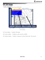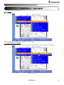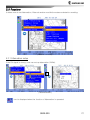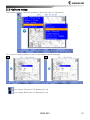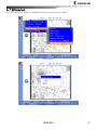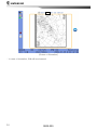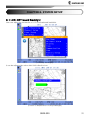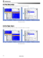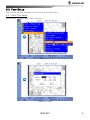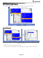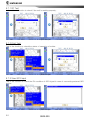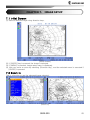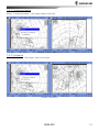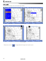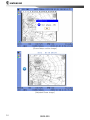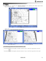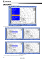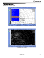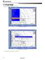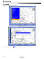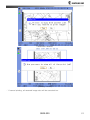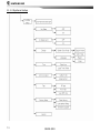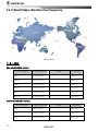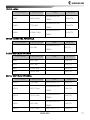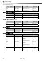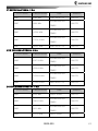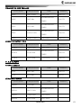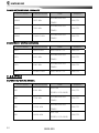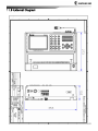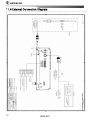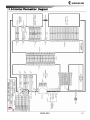
1
CHAPTER 1.Summary
1.1 CHARACTERISTICS .....................................................................................5
1.2 COMPOSITIONS.........................................................................................6
CHAPTER 2.Specification
2.1 NORMAL SPEC. ........................................................................................7
CHAPTER 3.Front part description
3.1 DESCRIPTION OF FRONT AND KEYPAD ............................................................... 8
3.1.1 Keypad........................................................................................... 9
3.2 REAR PART ........................................................................................... 10
3.3 LCD DISPLAY ........................................................................................ 11
3.4 ICONS ................................................................................................ 13
CHAPTER 4.MENU
4.1 INITIAL DISPLAY ...................................................................................... 14
4.2 SET UP FOR START RECEIVING ..................................................................... 15
4.2.1 Automatic Mode .............................................................................15
4.2.2 Manual Mode .................................................................................15
4.2.3 Forced Mode..................................................................................16
4.2.4 Timer Mode....................................................................................17
4.3 CHANNEL SETUP ..................................................................................... 19
4.3.1 Zone .............................................................................................20
4.3.2 Station ..........................................................................................20
4.3.3 Channel.........................................................................................21
4.3.4 Frequency .....................................................................................21
4.4 TIMER SETUP ........................................................................................ 23
4.4.1 Edit...............................................................................................23
SFAX-500
1
CHAPTER 5.FAX MENU
5.1 PRINT ................................................................................................. 25
5.1.1 Print Method setup..........................................................................25
5.1.2 Darkness setup ..............................................................................26
5.2 RECEIVER ............................................................................................. 27
5.2.1 Attenuation setup............................................................................27
5.2.2 External receiver setup ....................................................................28
5.2.3 Active Antenna setup ......................................................................28
5.3 HALFTONE SETUP ................................................................................... 29
5.4 EDIT STATION ........................................................................................ 30
5.5 IMAGE BACKUP ....................................................................................... 31
5.6 DELETE ALL IMAGES ................................................................................. 32
5.6 DELETE ALL IMAGES ................................................................................. 32
5.7 SIMULATION .......................................................................................... 33
CHAPTER 6.SYSTEM SETUP
6.1 LCD-KEY BOARD BACKLIGHT ................................................................... 35
6.2 KEY BEEP SETUP..................................................................................... 36
6.3 NO PAPER ALARM ................................................................................... 36
6.4 DISPLAY SETUP....................................................................................... 37
6.4.1 Screen color Mode..........................................................................37
6.4.2 Language setup..............................................................................38
6.5 TIME SETUP .......................................................................................... 39
6.5.1 Date/Time setup ............................................................................39
6.5.2 GPS Time Offset Setup ..................................................................40
6.6 COMMUNICATION SETUP ............................................................................ 41
6.6.1 NMEA-0183 ..................................................................................41
6.6.2 External Port .................................................................................42
6.7 TEST SETUP .......................................................................................... 43
2
SFAX-500
6.7.1 RF Test.........................................................................................44
6.7.2 Print Test ......................................................................................44
6.7.3 View GPS Input..............................................................................44
6.8 FACTORY SETUP ..................................................................................... 45
6.8.1 Clear Memory ................................................................................45
6.8.2 Load Default Setup ........................................................................46
6.8.3 Software Upgrade..........................................................................47
6.9 SYSTEM VERSION .................................................................................... 48
CHAPTER 7.IMAGE SETUP
7.1 INITIAL SCREEN ...................................................................................... 49
7.2 ZOOM IN .............................................................................................. 49
7.3 ZOOM OUT ............................................................................................ 50
7.4 ROTATE ............................................................................................... 50
7.4.1 Counterclockwise ..........................................................................51
7.4.2 Clockwise .....................................................................................51
7.5 LOCK .................................................................................................. 52
7.6 PHASE................................................................................................. 53
7.7 SYNC .................................................................................................. 55
7.8 EDIT COLOR .......................................................................................... 56
7.9 REVERSE COLOR ..................................................................................... 57
7.10 COPY IMAGE ........................................................................................ 58
7.11 DELETE IMAGE ...................................................................................... 59
7.12 PRINT ................................................................................................ 60
CHAPTER 8.SETUP AND HOW TO USE PRINTER
8.1 INSTALLATION ........................................................................................ 62
8.2 HOW TO REPLACE THE PAPER ...................................................................... 64
SFAX-500
3
CHAPTER 9.Circuit
9.1 OVERVIEW ............................................................................................ 67
9.2 CIRCUIT DESCRIPTION............................................................................... 69
CHAPTER 10.TROUBLESHOOTING
10.1 . OVERVIEW ......................................................................................... 71
10.2. MEASURING INSTRUMENT ........................................................................ 71
10.3 INSPECTION AND MAINTENANCE .................................................................. 72
10.3.1 Antenna.......................................................................................72
10.3.2 Power .........................................................................................72
10.3.3 Receiver ......................................................................................72
CHAPTER 11. Appendix
11.1 MENU TREE....................................................................................... 73
11.1.1 Menu...........................................................................................73
11.1.2 System Setup ...............................................................................74
11.1.3 Image Menu.................................................................................75
11.2 WORLD MAJOR WEATHER FAX FREQUENCY .................................................. 76
11.2.1 ASIA............................................................................................76
11.2.2 SOUTH AMERICA .........................................................................79
11.2.3 NORTH AMERICA .........................................................................79
11.2.4 PACIFIC OCEAN BASIN..................................................................82
11.2.5 EUROPE......................................................................................83
11.2.6 AFRICA .......................................................................................84
11.3 EXTERNAL DIAGRAM ............................................................................... 85
11.4 EXTERNAL CONNECTION DIAGRAM ............................................................... 86
11.5 INTERNAL CONNECTION DIAGRAM ................................................................ 87
4
SFAX-500
CHAPTER 1.
Summary
1.1 Characteristics
SFAX-500, weather fax receiver is a single body type with printer, is receiving 0.5MHz –
25MHz of weatherfax image and available to print on 10” wide paper. at the same time, it
displays the same data through 5.6” color LCD and available to save them by 30 images. It’s
available to print out and display them to LCD monitor when you need.
(1)
It controls each function generally by integrating important circuits such as control part,
power part, synthesizer part, receiver part and etc.
(2) It is available to control SFAX-500 weather fax receiver with operating a key pad in front.
(3) It is able to save max. 30 images.
(4) It is able to display again and print it out what you saved before.
(5) Receiving DATA from weather information centre as WMO standard
(6) Tuning is available to set on AUTO or Manual for the optimum receiving condition.
(7)
You can receive the best quality data with Auto channel receiving setting.
SFAX-500
5
1.2 Compositions
This equipment consists of basic composition and optional composition, mail equipment
consists of functional PCB.
NO.
1
(1)
(2)
(3)
Description
Model number
Unit
Weather fax receiver
SFAX-500
1Set
P102910
1
P102920
1
P102950
1
Part for receiving and
synthesizer
Part for control &
Power
Front Display
2
Power cable ASS’Y
3
Installer
4
Fix Bolt size
5
Fuse
6
Instruction Manual
SCN3-3M-D3
(P/N:574-0170-01)
INSTALLER
(P/N:H02-5001-07)
SUS
M5X10
5
NORMAL
M4 X12
3
5A, L=20mm
2
1
1
1
7
Dust cover
For SFAX-500 weather
fax Protection cover
8
Thermal recording paper
I.D. 12/O.D.40/W:260mm
(Length of paper:Abt.12m)
Remark
1
1Roll
Language select
[chart 1 Basic composition form]
NO.
Description
1
Whip Antenna
2
Antenna Cable
(1)
Antenna Coaxial cable
(2)
RF Coaxial connector
(3)
PRESS-RUBBER
Model Number
Unit
Remark
DAF-30R
1Set
FAX only
MP-20M(RG58)-0
(P/N:574-0150-02)
RG-58/U
(P/N:568-0058-21)
MP-C-58
(P/N:586-1401-3S)
RG-58 BUSHING
(P/N:714-4000-00)
1EA
1EA
1EA
3
Power
SP-310AD
1SET
4
Thermal recording paper
I.D.12/O.D.40/W:260mm
(Length of paper:Abt.12m)
1ROLL
[Chart 2 Optional composition form]
6
1Set
SFAX-500
20m
CHAPTER 2.
Specification
2.1 Normal Spec.
o
Frequency
: FAX 0.5MHz – 25MHz
o
Receiving method
: Double super heterodyne method
o
Modulation
: FAX(F3C/J3C)
o
Frequency stability
: Variation within 10Hz(within 0.3ppm)
o
Channel savable
: 30 channels
o
Save capacity
: FAX(30 PICTURE)
o
Screen display
: Black, White, Gray
o
Recording
: Solid-state recording by thermal head
o
Paper
o
Effective recording width : 252.0±0.2mm
o
Index of cooperation
: 576 or 288
o
Scanning speed
: 60, 90, 120, 180, 240 SPM(Scanning/Minutes)
o
Scanning resolution
: 8dots/mm
o
Power voltage
: DC 22V ~ 31V (24V -10% ~ +30%)
o
Current consumption
: Min 0.5A, Max 5A
o
Antenna
: WHIP Antenna(DAF30R) or WIRE Antenna 15M
o
Size
: W353 X D273 X H103
o
Weight
: 3.6Kg
System
: I.D.12/O.D.40/W:260mm (Length of paper:Abt.12m)
SFAX-500
7
CCHAPTER 3. Description of Front
3.1 Description of Front and keypad
①
②
③
④
⑤
⑥
⑦
⑧
LCD
Antenna connector
Speaker
Key pad
Printer Head Cover
Recording paper window
Recording cradle cover
Open Button
⑨ Paper Array Line
8
:
:
:
:
:
:
:
:
Displays weather fax image and setting screen.
Connects to receiving antenna
Available to check beep and receiving
Keys for operation such as Number, Menu, direction key
There are Printer head and printer mechanism in it.
Available to check whether a recording paper in or not
Install a thermal recording paper in it
While installing a recording paper, Mechanism will be opened if
you push this button.
: Please set by this line which you withdrew the recording paper.
SFAX-500
3.1.1 Keypad
: Use when input channel & frequency
: Open Main Menu
: Cancel settings or go back the menu before
: Switch for Auto or Manual of receiving mode
: Put gray tone on screen
: Use when control phase
: For feeding printing paper
: Move to channel setting menu
: Print received images
,
,
: For adjust volume
: For adjust tuning
: Move the cursor
,
,
(you can adjust the screen brightness by up and down arrows upon
Receive mode)
: For input setting
SFAX-500
9
3.2 Rear part
① Switch
: It is used for power on.
② Fuse(5A)
: There is 5A fuse in it.
③ Power (+24V)
: Connect to Power to the equipment.
④ Terminal Block : It is used for B.K , external reception input, GPS input and extra RS-422(232).
⑤ SD Card
: It is used for inserting SD card for version up or data backup.
⑥ Earth terminal
: Using for Earth
⑦ Input Antenna
: Receiving antenna is connected to this part.
10
SFAX-500
3.3 LCD Display
(1) Basic specification
- Basic resolution of LCD is set on 800 X 600.
Status display
Function display
Screen display
[LCD screen]
(2) Screen display
: Displays FAX images
(3) Function display : Available to select function on MENU
(4) Condition display : Displays a frequency receiving, Mode, Date, Time and etc.
SFAX-500
11
(5) Receiving screen
[The screen during receiving weather broadcasting]
① It is displayed the information for receiving images(channel, frequency,
IOC/RPM, time, receiving mode)
② It displays a condition of equipment.(Halftone, speaker, receiving
condition, antenna condition)
③ It displays the image of weather broadcasting which is been receiving.
④ It displays the information for the channel of weather broadcasting which
is been receiving.(channel, frequency, IOC/RPM, time, receiving mode)
12
SFAX-500
3.4 Icons
Displays an operation of Gray tone function
Displays an operation of Black and white tone function
Displays an operation of speaker and a level with a bar graph
Displays an operation of GPS
Displays an operation of an external receiving input
Displays an operation of diminution function
Displays this icon when timer is on
Displays this icon when receiving a weather fax broadcasting
Displays this icon during printing
Displays this icon when there is no paper ready
Displays this icon when there is an error on time(when time data is defective)
It disappears after inputting G.P.S or a correct time setting on Date, time Menu.
Displays this icon if external B.K signal is input
Displays the level of receiving signal
SFAX-500
13
CHAPTER 4. MENU
4.1 Initial Display
(1) Initial display is showed up when power on.
[Initial display]
(2) You can see Menu screen if you press [Menu] key.
(3) You can move cursor with [direction key], you can see subordinate menu if you press
[ENTER].
[Menu screen]
14
SFAX-500
4.2 Set up for Start Receiving
For start receiving setting, you can start receiving with selecting one of auto, manual, forced
and timer mode.
4.2.1 Automatic Mode
If you select Automatic mode, it starts to record from the start receiving signal comes.
[Automatic Mode]
4.2.2 Manual Mode
If you select Manual Mode, it starts to record from the phase signal comes
[Manual Mode]
SFAX-500
15
[Internal setting]
※IOC means a resolution of Print, RPM means Motor speed.
4.2.3 Forced Mode
If you select Forced Menu, it starts to record at once.
[Forced Mode]
※It is the same as Manual Mode for internal setting.
16
SFAX-500
4.2.4 Timer Mode
It begins to receive on time user set if you select timer mode.
[Timer mode]
[Timer operating screen]
※You should complete a timer setup in order to use timer mode.(Refer 4.4 Timer Sepup)
※You can see
icon during timer mode operating.
SFAX-500
17
(2) During Timer Mode standing by, automatically it works Clock mode if there’s no input more
than 1minute.
※During clock mode, it goes back to before screen if there’s any input
18
SFAX-500
4.3 Channel Setup
For receiving broadcasting what you want, this function is to select zone, station, channel,
frequency.(It is available to select channel directly with ‘CH’ key in front. Refer 4.3.5)
[Channel setting screen]
[Channel setting internal screen]
- It is available to select ‘Zone/Station/channel/Frequency with [Direction key].
- Zone
: Select Zone among Asia, America, Pacific Ocean Basin, Europe, Africa.
- Station
: Select one in the zone.
- Channel : Select a channel available from a station
- Frequency: if you want to select a channel directly, you can put the channel address directly
with [Number] key.
SFAX-500
19
4.3.1 Zone
Please select Zone where you are among Pacific, Atlantic, Indian, Mediterranean sea, Persia.
[Zone setting]
4.3.2 Station
Select Station(Nation) in order to receive weather fax broadcasting in your zone.
.
[Station setting]
20
SFAX-500
4.3.3 Channel
Select one of the channels of station which user selected. It is automatically connected to the
channel which is good for reception condition
[Channel setting]
4.3.4 Frequency
Set Frequency and please put frequency address directly.
[Frequency setting]
SFAX-500
21
4.3.5 Direct channel setting
This function is select channels directly with keypad
Channels setting ex)
- The initial number in the box is channel number.
22
SFAX-500
4.4 Timer Setup
This function is for receiving data automatically on the time what user set.
[Timer setting]
4.4.1 Edit
If you select Timer Setup, you will move this page as below.
[Timer setting screen]
- You can select multi-ply when time is different.
- When ‘off’ is on the setting screen, Timer mode is not working.
SFAX-500
23
Press [ENTER] key where you want to set in the list, and then you can set timer as below.
[Timer setting]
- Set ‘Zone/Station/Channel/Frequency’ the same as channel setting.
- IOC/Speed
: means resolution for image receiving and printing speed
-Start, End time
: Set a start time and end time for receiving data
- On/Off
: select timer on or timer off
- Save/Exit
: Save setting data / go back to Menu list.
24
SFAX-500
CHAPTER 5.
FAX MENU
5.1 Print
User can set print method and darkness for printing.
5.1.1 Print Method setup
User can select one of the modes (Auto, manual and timer) if print method is selected.
[Print menu]
SFAX-500
25
(1)Manual, Auto and Timer mode
- If manual is selected, it can be printed the receiving image desired by user.
- If Auto is selected, all of the receiving images are printed.
-If Auto on Timer mode is selected, the receiving images in timer mode are printed
automatically.
5.1.2 Darkness setup
Darkness is adjusted over 10 ~ 100 by using direction button.
[set up Darkness]
26
SFAX-500
5.2 Receiver
It allows user to set Attenuation, External receiver and Active antenna related to receiving.
[Menu of receiver]
5.2.1 Attenuation setup
If the RX signal is strong, user can set up attenuation (20Db).
[Attenuation]
※
Icon is displayed when the function of Attenuation is operated.
SFAX-500
27
5.2.2 External receiver setup
User can set the status of external receiver.
[External receiver]
※
Icon is displayed when external receiver is operated.
5.2.3 Active Antenna setup
User can set the status of active antenna.
[Active antenna]
28
SFAX-500
5.3 Halftone setup
The receiving signal, selected to black or grey tone color, is transacted.
(1) In case of setting Halftone, Icon on the display will be changed.
[Halftone ON]
[Halftone OFF]
※
Icon means Grey tone (16 darkness) is set.
※
Icon means Black tone (2 darkness) is set.
SFAX-500
29
5.4 Edit Station
It allows user to set the desired station.
[Menu of station]
-
[Picture of Edit station]
Set Private in Zone.
Set Private in Staion.
For Channel, select the channel desired.
User can set Call Sign at user’s option
Set Frequency to be received.
30
SFAX-500
5.5 Image Backup
Check the status of Image Backup.
[Menu of Image back up]
[Picture of Image Backup]
- In case of selection of Manual, images can be saved over 30 images in memory. If the saved
images exceed 30, the saved images are deleted from first image. (It can not be saved in SD card)
- In case of selection of Auto, internal memory is same as Manual mode. All the RX images are
saved in SD card automatically.
SFAX-500
31
5.6 Delete All Images
Check if user delete all the save images or not.
[Picture of Delete all Images]
※ Check it again before deleting all images.
[Before deleted all images]
※ It can not be restored after deleted.
32
SFAX-500
5.7 Simulation
It is the function of testing of operation without actual communication.
[Simulation]
[Picture of Simulation]
SFAX-500
33
[Picture of Simuation]
※ In case of simulation, SIM will be showned.
34
SFAX-500
CHAPTER 6. SYSTEM SETUP
6.1 LCD-KEY board Backlight
User can adjust the brightness of LCD and keyboard backlight.
[LCD/Key backlight]
It can be adjusted by using right & left direction key
[Picture of adjustment LCD/Key backlight]
SFAX-500
35
6.2 Key Beep setup
User can set key beep which is happened when pressed key button.
[Setup key beep]
6.3 No Paper Alarm
User can set No Paper Alarm for alarm sound when there is no paper.
[No paper alarm]
36
SFAX-500
6.4 Display setup
In this menu, User can set Screen color Mode and Language.
6.4.1 Screen color Mode
User can set the screen color of outside of image to Daylight mode or Night mode.
[Screen color Mode]
[Daylight Mode]
[Night Mode]
- In Daylight Mode, the outside of the image is shown as white color.
- In Night Mode, the outside of the image is shown as dark grey color.
SFAX-500
37
6.4.2 Language setup
User can select language to English or Korean
[Language]
[Setup language]
38
SFAX-500
6.5 Time Setup
User can set the time deviation of the unit’s time and GPS input.
6.5.1 Date/Time setup
User can set a current date / time of the unit.
[Date/time]
[Date/time setup]
SFAX-500
39
6.5.2 GPS Time Offset Setup
User can set a function to offset the GPS time differences.
[Menu of GPS Time Offset]
[GPS Time Offset Setup]
40
SFAX-500
6.6 Communication Setup
User can set communication environment by using external connection terminal.
[Communication Setup]
6.6.1 NMEA-0183
[NMEA-0183 Setup]
※ NMEA-0183 is port for receiving GPS signal.
※ Set up the communication speed of external device on the same speed as SFAX-500.
SFAX-500
41
6.6.2 External Port
[Export Port Setup]
※ User can set RS-232, 422 Communication through the switch of the CUP Board.
[Internal CPU shield]
① Open the cover of printer head by pressing the printer open,
② Unlock the bolts of the shield for paper, and also unlock the bolt of the back side.
③ After removed the connectors of keyboard PCB, tip back the keyboard PCB.
④ If user pull the switch of the hole of CPU shield to downward direction, the RS-232 communication
will be set. If user pull it to upward direction, the RS-422 communication will be set.
- RS-232 to be set when taking out the goods.
- Set up the communication speed of external device on the same speed as SFAX-500.
※ In case of user’s random operation, it is possible to cause a breakdown.
42
SFAX-500
6.7 Test Setup
User can test RX, print and GPS input of the unit.
[Test Mode]
[Test Menu]
SFAX-500
43
6.7.1 RF Test
Is the self test function to check if the unit is working properly.
[RF Test]
6.7.2 Print Test
This is the function to check the status of operation of printer.
[Print Test]
6.7.3 View GPS Input
This is the function to check the RX condition of GPS signal in case of connecting external GPS
device.
[GPS Test]
44
SFAX-500
6.8 Factory Setup
User can initialize the unit / memory and upgrade software.
[Factory Setup]
6.8.1 Clear Memory
This function allows users to initialize the memory of the unit and the user’s setup data.
[Menu before initialization of memory]
[Menu before initialization]
- In clear memory mode, it is available to initialize by selecting fax image or user setup.
(In case of initialization of fax image, both external/internal memories are deleted.)
- Before initialization, check it again if the initialization is required.
- The deleted data can not be restored.
SFAX-500
45
6.8.2 Load Default Setup
It makes the setup condition return to initial condition.
[Load Default Setup]
[Load Default Setup]
※ Before initialization, check it again if the initialization is required.
※ The deleted data can not be restored.
46
SFAX-500
6.8.3 Software Upgrade
This function is used when the unit is required software upgrade.
[Software Upgrade]
[The screen of Software Upgrade]
- Execute ‘RUN’ after inserting the SD card with the software for upgrading to the socket.
- Turn the unit off after checking the completion of software update.
※ If the power is off for upgrading the software, it causes a breakdown.
※ 2G SD Memory is not supported. (SCHC memory is supported)
SFAX-500
47
6.9 System Version
This is the function to check a version of unit.
[System Version]
[The Screen of System version]
48
SFAX-500
CHAPTER 7.
IMAGE SETUP
7.1 Initial Screen
(1) Select a desired image using direction keys.
[Initial Screen]
(2) If [ENTER] key is pressed, the image is selected.
(3) If [MENU] is pressed, image setup menu is displayed.
(4) User can move a cursor by selecting [Direction key], and the selected menu is executed if
[ENTER] is pressed
7.2 Zoom In
This is a function to see the enlarged image selected.
[Zoom In]
SFAX-500
49
7.3 Zoom out
This is the function to see the reduced image selected.
[Zoom Out]
7.4 Rotate
This is a function to rotate the selected image.
[Rotate]
※ User can rotate the image to clockwise direction or counterclockwise direction.
※ If user select ‘Exit’ after rotating the image, the image is saved automatically.
50
SFAX-500
7.4.1 Counterclockwise
Select “Counterclockwise”, the image rotate to the left.
[Rotate Counterclockwise]
7.4.2 Clockwise
Select “Clockwise”, the image rotate to the right.
[Rotate Clockwise]
SFAX-500
51
7.5 Lock
Function for protecting from the saved image delete.
[Lock]
[Lock Image]
※Show the Lock Icon
52
on Image when the image lock function work.
SFAX-500
7.6 Phase
The SFAX start to receive the broadcast, the image will be separated two parts by
Black Line called DEAD SECTOR the cause of the PHASE MISMATCHING.
So, the Phase function can adjust ‘PHASE MISMATCHING’ when it will be happened.
(1) Select the button
on the keypad or ‘Phase’ on Menu
[Phase Image]
(2)Check the location of ‘DEAD SECTOR’ by graduated ruler and input the graduated
ruler number with arrow button or keypad.
[Phase Setup Image]
※The sphere of value can be changed from“0 to 31 and ‘DEAD SECTOR’ location can be
chaged by the value.
SFAX-500
53
[Phase Setup confirm image]
[Adjusted Phase Image]
54
SFAX-500
7.7 Sync
(1)This function for matching the dynamic climate by fine adjusting the Phase signal when
‘DEAD SECTOR’ slants.
[ Sync Menu ]
(1) Can slant dynamic climate by .
[Slant to the right]
[Slant to the left]
※The adjustment sphere can control from200 to -200.
※Use button
on the keypad, increase number of sync. and the image slant to the left.
`
※Use button
on the keypad, decrease number of sync. and the image slant to the right.
SFAX-500
55
7.8 Edit Color
Edit the saved image’s background color.
[Edit Color]
(1) Black background and gray background
[Monochrome background]
[ Gray Background]
※Don’t change the left top icon as like FAX Menu.
56
SFAX-500
7.9 Reverse Color
Reverse color image on display.
[Reverse Color Menu]
[Reversed Color Image]
SFAX-500
57
7.10 Copy image
Copy the received image to SD Card.
[Copy Image Menu]
[Copy Image Display]
- The image will be saved as *.GIF file.
58
SFAX-500
7.11 Delete Image
Function for deleting the select image.
[Delete Menu]
(1) Check again to delete or not before deleting image.
[Delete Image]
(2)Select ‘Yes’ and then delete the image.
※the deleted image never can be restored.
SFAX-500
59
7.12 Print
Function for printing received image.
[printing mode]
[ printing Display]
※ When use print fuction,
icon is appear and do process of printing.
※ When doing print also choose image and reserve print.
60
SFAX-500
[reservation display]
[Printing Cancel]
※ If cancel printing, all reserved image also will be canceled too.
SFAX-500
61
Chapter 8. USAGE of Printer and Installation
8.1 Installation
1
fix on the
installation panel
with M5*10mm
pararel.
Push SFAX-500 to
arrow direction
2
Open print head
cover by push open
button
3
62
SFAX-500
Open a print paper
cover.
4
5
Fix on the
installation panel
with M4*14mm bolt
Close a print paper
cover.
6
SFAX-500
63
8.2 How to replace the paper
1
Press PUSH button.
2
Take empty roll paper
out to arrow direction.
Insert new paper
arrow direction.
3
64
SFAX-500
to
Put
4
the
paper
under the sensor
and pull the paper
out.
Pull the paper out
5
some
and
close
the front cover.
SFAX-500
65
※ Caution for image print-out
※
※
※
※
Power off and open a print head cover.
Wipe a heater line by using a soft cloth putting alcohol if there’s a line or spot on printed image.
Do not touch a heater line as the printing quality can be no good.
Do not touch a heater line after print-out as it is hot.
66
SFAX-500
Chapter 9 Circuit Diagram
9.1 Overview
[SFAX-500 RF-BOARD]
SFAX-500
67
[SFAX-500 MAIN-BOARD ]
- SFAX-500 consists front keyboard, LCD display, receiver & synthesizer, Control, power and
printer .
- Power: DC +22V ~ +31V (24V: –10%, +30%)
68
SFAX-500
9.2 Circuit Description
(1)
Receiver
[ Reception Block Diagram ]
(2) Local Synthesizer
[Synthesizer
Block Diagram]
SFAX-500
69
(3) Power Circuit
[Power Circuit Diagram]
* Power circuit: Power circuit receives DC24V and supplies 24V through a
protection and regulated voltage circuit.
* Main Power Circuit & Protection and Sensor Circuit are contains.
70
SFAX-500
Chapter 10 TROUBLESHOOTING
10.1 . Overview
z The most of reason which causes trouble is related to mechanical and electrical
reasons in the internal and external of device and these reasons can be
prevented by periodical inspection and maintenances. Also this device equips with
all kid of protection circuit to protect circuits and parts. However, if there are any
troubles that caused a difficulty to operate then it needs to be repaired in fast
and rational manner. To maintain its original performance and life expectancy,
periodical inspection and maintenance is required. Please be aware of matters to
be attended as below before inspection and maintenance to avoid improper
maintenances.
10.2. Measuring Instrument
z This device is designed accordingly to international wireless communication
laws and measuring instruments for inspection and maintenance is needed to be
inspected and tested by an authorized agency. For daily inspection and
maintenance, following measuring instruments are needed.
Measuring Instrument for inspection and repair
1
A multi meter for the measurement of resistor, voltage and current
2
A frequency Counter that can measure 100MHz bandwidth
3
An oscilloscope that can measure 100MHz bandwidth
4
A Signal generator that can measure 100MHz bandwidth
5
Others
[Table 4. The list of measuring instruments for inspection and repair]
SFAX-500
71
10.3 Inspection and Maintenance
10.3.1 Antenna
z If there is difficulty in communication caused by noise, signal reception and so
on, check an antenna first whether there is any defection or not and then check
followings.
(1) Do self test.
(2) Whether a whip antenna is properly connected.
(3) Whether metallic object is near an antenna or not.
(4) Whether the connection and insulation between an antenna and receiver is
proper or not.
10.3.2 Power
z If there is no display even though the power is on, following are needed to be
checked.
(1) Whether fuse is disconnected or not (The rated current of fuse is 5A)
(2) Whether the power connector is properly connected or not. (If the polarity of
power is opposite, the device will not work)
(3) Check the voltage in the power supply connector. (If it is between DC 22~31V,
it is normal.)
10.3.3 Receiver
Make sure all interface devices are properly connected.
(1) Do self test.
(2) Check the connection between P102910 PCB in device and the cable replace
with one if the board is defected.
72
SFAX-500
Chapter 11. Appendix
11.1 MENU TREE
11.1.1 Menu
SFAX-500
73
11.1.2 System Setup
74
SFAX-500
11.1.3 Image Menu
SFAX-500
75
11.2 World Major Weather Fax Frequency
[World Map]
11.2.1 ASIA
BEIJING(PEKING)-CHINA
CALL SIGNS
FREQUENCIES
TIME
RPM/IOC
BAF6
5526.9 kHz
120/576
BAF36
8121.9 kHz
120/576
BAF4
10116.9 kHz
120/576
BAF8
14366.9 kHz
120/576
BAF9
16025.9 kHz
120/576
BAF33
18236.9 kHz
120/576
BEIJING(PEKING)-CHINA
CALL SIGNS
76
FREQUENCIES
TIME
RPM/IOC
3SD
8461.9 kHz
120/576
3SD
12831.9 kHz
120/576
3SD
16903.9 kHz
120/576
SFAX-500
TOKYO-JAPAN
CALL SIGNS
FREQUENCIES
TIME
RPM/IOC
ALLBROADCAST
JMH
3622.5 kHz
120/576
TIMES
ALLBROADCAST
JMH2
7795 kHz
120/576
TIMES
ALLBROADCAST
JMH4
13988.5 kHz
120/576
TIMES
PEVEK-CHUKOTKA PENINSULA
CALL SIGNS
FREQUENCIES
TIME
RPM/IOC
ALLBROADCAST
148 kHz
90/576
TIMES
TAIPEI-REPUBLIC OF CHINA
CALL SIGNS
FREQUENCIES
TIME
RPM/IOC
BMF
4616 kHz
120/576
BMF
8140 kHz
120/576
BMF
13900 kHz
120/576
BMF
18560 kHz
120/576
SEOUL-REPUBLIC OF KOREA
CALL SIGNS
FREQUENCIES
HILL2
3585 kHz
HILL2
5857.5 kHz
TIME
1200-0000 UTC
RPM/IOC
120/576
ALLBROADCAST
120/576
TIMES
ALLBROADCAST
HILL2
7433.5 kHz
120/576
TIMES
ALLBROADCAST
HILL2
9165 kHz
120/576
TIMES
HILL2
13570 kHz
0000-1200 UTC
SFAX-500
120/576
77
BANGKOK-THAILAND
CALL SIGNS
HSW64
FREQUENCIES
TIME
RPM/IOC
7395.0 kHz
120/576
KYODO NEWS AGENCY-JAPAN/SINGAPORE
CALL SIGNS
FREQUENCIES
TIME
RPM/IOC
ALLBROADCAST
JJC
4316 kHz
TIMES
ALLBROADCAST
JJC
8467.5 kHz
TIMES
ALLBROADCAST
JJC
12745.5 kHz
TIMES
ALLBROADCAST
JJC
16971 kHz
TIMES
ALLBROADCAST
JJC
17069.6 kHz
TIMES
ALLBROADCAST
JJC
22542 kHz
TIMES
0740-1010,
9VF/252
1415-
16035 kHz
1815
0740-1010,
9VF/252
1415-
17430 kHz
1815
NORTHWOOD-UNITED KINGDOM (PERSIAN GULF)
CALL SIGNS
FREQUENCIES
GYA
6834 kHz
GYA
12390 kHz
TIME
1800-0800 UTC
RPM/IOC
120/576
ALLBROADCAST
120/576
TIMES
GYA
78
18261 kHz
0800-1800 UTC
SFAX-500
120/576
11.2.2 SOUTH AMERICA
RIO DE JANEIRO-BRAZIL
CALL SIGNS
FREQUENCIES
TIME
RPM/IOC
ALLBROADCAST
PWZ-33
12665 kHz
120/576
TIMES
ALLBROADCAST
PWZ-33
16978 kHz
120/576
TIMES
VALPARAISO PLAYA ANCHA-CHILE
CALL SIGNS
FREQUENCIES
TIME
RPM/IOC
ALLBROADCAST
CBV
4228 kHz
120/576
TIMES
ALLBROADCAST
CBV
8677 kHz
120/576
TIMES
ALLBROADCAST
CBV
17146.4 kHz
120/576
TIMES
11.2.3 NORTH AMERICA
HALIFAX,NOVA SCOTIA-CANADA
CALL SIGNS
FREQUENCIES
TIME
RPM/IOC
ALLBROADCAST
CHF
122.5 kHz
120/576
TIMES
ALLBROADCAST
CHF
4271 kHz
120/576
TIMES
ALLBROADCAST
CHF
6496.4 kHz
120/576
TIMES
ALLBROADCAST
CHF
10536 kHz
120/576
TIMES
ALLBROADCAST
CHF
13510 kHz
120/576
TIMES
SFAX-500
79
IQALUIT,N.W.T-CANADA
CALL SIGNS
FREQUENCIES
TIME
RPM/IOC
VFF
3253 kHz
2100-2330 UTC
120/576
VFF
7710 kHz
0010-0900 UTC
120/576
RESOLUTE,N.W.T-CANADA
CALL SIGNS
FREQUENCIES
TIME
RPM/IOC
VFR
3253 kHz
0010-0900 UTC
120/576
VFR
7710 kHz
2100-2330 UTC
120/576
SYDNEY,NOVA SCOTIA-CANADA
CALL SIGNS
FREQUENCIES
TIME
RPM/IOC
VCO
4416 kHz
1121-1741 UTC
120/576
VCO
6915.1 kHz
2200-2331 UTC
120/576
INUVIK-CANADA
CALL SIGNS
VFA
FREQUENCIES
TIME
8457.8 kHz
RPM/IOC
120/576
KODIAK,ALASKA-U.S.A
CALL SIGNS
FREQUENCIES
TIME
RPM/IOC
ALLBROADCAST
NOJ
2054 kHz
120/576
TIMES
ALLBROADCAST
NOJ
4298 kHz
120/576
TIMES
ALLBROADCAST
NOJ
8459 kHz
120/576
TIMES
ALLBROADCAST
NOJ
12412.5 kHz
120/576
TIMES
80
SFAX-500
PT.REYES,CALIFORNIA-U.S.A
CALL SIGNS
FREQUENCIES
NMC
4346 kHz
NMC
8682 kHz
TIME
0140-1608 UTC
RPM/IOC
120/576
ALLBROADCAST
120/576
TIMES
ALLBROADCAST
NMC
12786 kHz
120/576
TIMES
ALLBROADCAST
NMC
17151.2 kHz
120/576
TIMES
NMC
22527 kHz
1840-2356 UTC
120/576
NOW ORLEANS,LOUISANA-U.S.A
CALL SIGNS
FREQUENCIES
TIME
RPM/IOC
ALLBROADCAST
NMG
4317.9 kHz
120/576
TIMES
ALLBROADCAST
NMG
8503.9 kHz
120/576
TIMES
ALLBROADCAST
NMG
12789.9 kHz
120/576
TIMES
NMG
17146.4 kHz
1200-2045 UTC
120/576
BOSTON,MASSACHUSETTS-U.S.A
CALL SIGNS
FREQUENCIES
NMF
4235 kHz
NMF
6340.5 kHz
TIME
0230z-1028z
RPM/IOC
120/576
ALLBROADCAST
120/576
TIMES
ALLBROADCAST
NMF
9110 kHz
120/576
TIMES
NMF
12750 kHz
1400z-2228z
SFAX-500
120/576
81
11.2.4 PACIFIC OCEAN BASIN
CHARLEVILLE-AUSTRALIA
CALL SIGNS
FREQUENCIES
VMC
2628 kHz
VMC
5100 kHz
TIME
0900-1900
RPM/IOC
120/576
ALLBROADCAST
120/576
TIMES
ALLBROADCAST
VMC
11030 kHz
120/576
TIMES
ALLBROADCAST
VMC
13920 kHz
120/576
TIMES
VMC
20469 kHz
1900-0900
120/576
WILUNA-AUSTRALIA
CALL SIGNS
FREQUENCIES
VMW
5575 kHz
VMW
7535 kHz
TIME
1100-2100
RPM/IOC
120/576
ALLBROADCAST
120/576
TIMES
ALLBROADCAST
VMW
10555 kHz
120/576
TIMES
ALLBROADCAST
VMW
15615 kHz
120/576
TIMES
VMW
82
18060 kHz
2100-1100
SFAX-500
120/576
WELLINGTON-NEW ZEALAND
CALL SIGNS
FREQUENCIES
ZKLF
3247.4 kHz
ZKLF
5807 kHz
TIME
0945-1700
RPM/IOC
120/576
ALLBROADCAST
120/576
TIMES
ALLBROADCAST
ZKLF
9459 kHz
120/576
TIMES
ALLBROADCAST
ZKLF
13550.5 kHz
120/576
TIMES
ZKLF
16340.1 kHz
2145-0500
120/576
HONOLULU,HAWAII-U.S.A
CALL SIGNS
FREQUENCIES
KVM70
9982.5 kHz
KVM70
11090 kHz
TIME
0519-1556
RPM/IOC
120/576
ALLBROADCAST
120/576
TIMES
KVM70
16135 kHz
1719-0356
120/576
11.2.5 EUROPE
ATHENS-GREECE
CALL SIGNS
FREQUENCIES
TIME
RPM/IOC
SVJ4
4481 kHz
120/576
SVJ4
8105 kHz
20/576
MURMANSK-RUSSIA
CALL SIGNS
FREQUENCIES
RBW41
5336 kHz
RBW41
6445.5 kHz
TIME
RPM/IOC
ALLBROADCAST
TIMES
RBW41
7908.8 kHz
1900-0600
RBW48
10130 kHz
0600-1900
SFAX-500
83
HAMBURG/PINNEBERG-GERMANY
CALL SIGNS
FREQUENCIES
TIME
RPM/IOC
ALLBROADCAST
DDH3
3855 kHz
120/576
TIMES
ALLBROADCAST
DDK3
7880 kHz
120/576
TIMES
ALLBROADCAST
DDK6
13882.5 kHz
120/576
TIMES
NORTHWOOD-UNITED KINGDOM
CALL SIGNS
FREQUENCIES
GYA
2618.8 kHz
GYA
4610 kHz
TIME
2000-0600 UTC
RPM/IOC
120/576
ALLBROADCAST
120/576
TIMES
ALLBROADCAST
GYA
8040 kHz
120/576
TIMES
GYA
11086.5 kHz
0600-2000 UTC
120/576
11.2.6 AFRICA
CAPENAVAL-SOUTH AFRICA
CALL SIGNS
FREQUENCIES
TIME
RPM/IOC
16Z-06Z
ZSJ
4014 kHz
120/576
(WHEN AVILABLE)
ALLBROADCAST
ZSJ
7508 kHz
120/576
TIMES
ALLBROADCAST
ZSJ
13538 kHz
120/576
TIMES
06Z-16Z
ZSJ
18238 kHz
120/576
(WHEN AVILABLE)
84
SFAX-500
11.3 External Diagram
SFAX-500
85
11.4 External Connection Diagram
86
SFAX-500
11.5 Internal Connection Diagram
SFAX-500
87