1
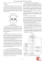
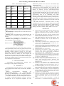
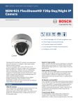
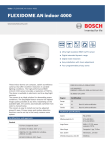
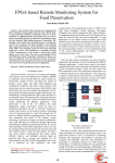
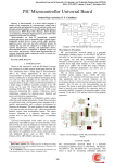
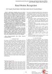
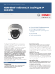
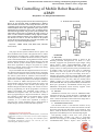
International Journal of Innovative Technology and Exploring Engineering (IJITEE) ISSN: 2278-3075, Volume-1, Issue-3, August 2012 The Controlling of Mobile Robot Based on ARM9 Roopashree S S, Manjunath Lakkannavar II. HARDWARE SYSTEM Abstract— In this proposed work the robot is built using two dc motors for the movement which is administered by AT89C51 Microcontroller, the obstacle is detected by ultrasonic sensor, the controlling of the robot is done by using the resources of MINI 2440 development board. The application of this system can be implemented at archeological survey, place of natural disaster and industrial applications. The previous system of Mobile robot which relies on PC System to coordinate the whole resources, in order to achieve advanced arithmetic among different module, and to realize intelligent behavior just as human beings by plan and decision. In order to overcome the hitch in the previous system, this work is proficient where it is stable and reliable, with low-power, tiny-volume and high integration. Keywords— ARM9, L293D, LCD, MINI 2440, ultrasonic sensor, Linux,. I. INTRODUCTION This paper The PC System of mobile robot is equal to the brain of Mobile robot, which is the physical basis to reflect the intelligence of mobile robot. Usually, Mobile robot relies on PC System to coordinate the whole resources, in order to achieve advanced arithmetic among different module, and to realize intelligent behavior just as human beings by plan and decision. The PC system is another power consumer, so it is much more significant to design a low-power PC system. However, at present, the PC system for mobile robot usually uses common computer but in this Project the MINI 2440 development board will act like a PC. Based on the Structure of the original robotic, pneumatic systems, sensors and motor control circuits, we have designed the control system based on AT89C51 microcontroller to achieve the control of the manipulator, to improve the MCU applications in industrial production. The design of intelligent robot is based on ARM microprocessor and AT89C51 microcontroller which control Two-wheel drive robot. The design of the intelligent robot includes system design, the hardware design and software design. The control of robot is done by programming in C & the programme is executed in Fedora environment and controlled using buttons of MINI2440 development board. The movement of robot is done by programming in C & ported in AT89C51. Ability of the computer to think similar to the human brain is called Artificial intelligence. The PC system is another power consumer, so it is much more significant to design a low-power PC system. Intelligent robot is characteristic of flexible design, accurate control and stable operation. A. Mini 2400 The MINI2440 Development Board is based on the Samsung S3C2440 microprocessor. Its PCB is 4- layer boarded, equipped with professional equal length wiring which ensures signal integrity.MINI2440 boards are manufactured in mass production and released with strict quality control. On startup it directly boots preinstalled Linux by default. There are no extra setup steps or configuring procedures to start the system. It is easy for users to get started. Anyone with very basic knowledge about the C language can become proficient. Friendly ARM. Mini 2440 with 400 MHz Samsung S3C2440 ARM9 processor. [3]The board measures 100 x 100 mm, ideal for learning about ARM9 systems. On board 64M SDRAM and NAND Flash,2M NOR flash with preinstalled BIOS, 100M Ethernet RJ-45 port (powered by the DM9000 network chip), The MINI2440 development board currently supports Linux 2.6.29 and WinCE.NET 5.0.Final Stage B. S3C2440 SAMSUNG S3C2440 uses 16/32 bit ARM920T RISC technology for the core. Its main Frequency is 400M Hz. and transfers it to the SDRAM under control of the DMA; the other is called code mode, which transmits the image data to the SDRAM in YCbCr4:2:0 or 4:2:2 format. C. LV-MaxSonar-EZ1 Sensor The ultrasonic sensor is used find the obstacle. If any obstacle in front of the sensor, it detects the obstacle in all the directions and sends the information to the AT89C51, then 89C51 sends the Distance between obstacle and robot and displayed on the ARM9 processor board through Zigbee. The operating voltage is from 2.5V- 5.5V, power the LV-MaxSonar-EZ1 provides very short to long-range detection and ranging, in an incredibly small package. The LV-MaxSonar-EZ1 detects objects from 0-inches to Manuscript received on August, 2012. Roopashree S S, VLSI Design and Embedded Systems, Visveswaraiah Technological University/ UTL Tech Ltd, VTU Extn Centrre/ Bangalore, INDIA, Manjunath Lakkannavar, VLSI Design and Embedded Systems, Visveswaraiah Technological University/ UTL Tech Ltd, VTU Extn Centrre/ Bangalore, INDIA,7411403673. 20 The Controlling of Mobile Robot Based on ARM9 254-inches (6.45-meters) Information. and provides sonar range A. Implementation of Controlling of the Robot. The controlling of robot is done by programming in C & the program is executed in Fedora environment. Fedora, formerly Fedora Core, is an RPM-based, general purpose collection of software, including an operating system based on the Linux kernel, developed by the community-supported Fedora Project and sponsored by Red Hat. Fedora’s flexibility makes it capable of serving as a digital repository for a variety of use cases. The Fedora Project's mission is to lead the advancement of free and open source software and content as a collaborative community. The movement of robot is done by programming in C & the program is executed in Keil μ-Vision. In this project it is used to compile the LCD, DC motor, Zigbee interfacing program with AT89C51. D. L293D L293D is a dual H-Bridge motor driver, So with one IC we can interface two DC motors which can be controlled in both clockwise and counter clockwise direction and if you have motor with fix direction of motion the you can make use of all the four I/Os to connect up to four DC motors. L293D has output current of 600mA and peak output current of 1.2A per channel. In this project two motors are used to control the movement of robot. B. Design of Controlling of the Robot. Figure 3. is the flow chart for Controlling of the Robot, initially it checks for the parameter parsing, in the command line the object files of Robot-Control is executed by using vi editor commands of Linux environment. The controlling of robot is done by programming in C & the program is executed in Fedora environment. The design procedure is as follows, 1. Initialize serial port 1 to baud rate 9600. 2. Is any key is pressed, if yes means it will go to next step, if no means go back and check is any key is pressed. 3. Is key “0” pressed means it transmit data @@!*#F to robot side through Zigbee, if @@!*#F data is received then it display received data, after data is received then go back and check if any key is pressed. If key “0” is not pressed then go to next step. 4. Step 4: Is key “1” pressed means it transmit data @@!*#B to robot side through Zigbee, if @@!*#B data is received then it display received data, after data is received then go back and check if any key is pressed. If key “1” is not pressed then go to next step. Figure 2. H-Bridge Motor driver. "H‐Bridge" is also known as "Full Bridge". Basically there are four switching elements in the H‐Bridge as shown in the above figure. When these switches are turned on in pairs motor changes its direction accordingly. Like, if we switch on S1 and S4 then motor rotate in forward direction, as current flows from power supply through the motor coil goes to ground via switch S4. E. Robot “Robot is defined as mechanical design that is capable of performing human tasks or behaving in a human like manner”. The robot contains a programmable device to control the operation and perform a particular task. Robot performs a flexible but restricted number of operations. They are widely used in industrial applications, travelling to remote place and mining area related applications. The sensor is fixed to the robot. This device will sence the happenings in and around the robot and it provides the signals to the controller with relevant information so that the controller can decide the task to be performed. The controller functions as the brain of the robot. It is performed in such a way that depending on the instruction given by the user it controls the functioning of the robot. The DC motors are used to make the movement of the robot in various directions and they are activated by the sensors. III. SYSTEM SOFTWARE DESIGN The software design of the system consists of two modules, one is controlling of the robot and other one is movement of robot. The project is implemented by using MINI 2440 development board & Robot. The controlling of robot is done by programming in C & the programme is executed in Fedora environment and controlled using buttons of MINI2440 development board. The movement of robot is done by programming in C & ported in AT89C51. Figure 3. Flow chart for Controlling of the Robot 21 International Journal of Innovative Technology and Exploring Engineering (IJITEE) ISSN: 2278-3075, Volume-1, Issue-3, August 2012 5. Is key “2” pressed means it transmit data @@!*#L to robot side through Zigbee, if @@!*#L data is received then it display received data, after data is received then go back and check if any key is pressed. If key “2” is not pressed then go to next step. C. Design of Movement of Robot. The flow chart in figure 2 briefly explains about the design of Movement of Robot is done by programming in C and the program is executed in Keil μ-Vision. The design procedure is as follows, Figure 4. Flow chart for Controlling of the Robot 1. 2. 3. 4. 5. 6. After power on wait for 30minutes, then initialize LCD for two line mode. Initialize microcontroller into UART mode with 9600 baud rate. Initially display title of the project on LCD. Initialize microcontroller into receiver mode. Initially @@!*# these commands are read, then waiting for next command that is F. If “F” is received then will move in forward direction and both motors are rotated in clockwise direction. If any obstacle is detected in front of the robot , the robot will stop its movement and measure the distance and displayed on LCD then enter into the transmit mode and sends the distance information to controller side through Zigbee. If the command “F” is not received then go to next step. If the command “B” is received, motor 1 and motor 2 are rotated in anti-clockwise direction for 2seconds and then stop its movement and again go back and initialize microcontroller into receiver mode. III. RESULTS The above truth table shows the actual distance and shown distance in cm between obstacle and Robot. The Ultrasonic sensor is used to detect the obstacle in all the directions. 22 The Controlling of Mobile Robot Based on ARM9 Table 1: Table of Result Analysis Actual distance in cm Shown distance in cm Distance error in cm Error percentage (%) 32 31 1 96.87 42 40 2 95.23 38 37 1 97.36 18 16 2 88.88 20 18 2 90.00 50 49 1 98.00 ARM-based products were the Acorn Archimedes range introduced in 1987. The relative simplicity of ARM processors makes them suitable for low power applications. As a result, they have become dominant in the mobile and embedded electronics market, as relatively low-cost, small microprocessors and microcontrollers. In 2005, about 98% of the more than one billion mobile phones sold each year used at least one ARM processor. As of 2009, ARM processors account for approximately 90% of all embedded 32-bit RISC processors and are used extensively in consumer electronics, including personal digital assistants (PDAs), mobile phones, digital media and music players, hand-held game consoles, calculators and computer peripherals such as hard drives and routers. The ARM architecture is licensable. There are many Companies that are current or former ARM licensees ARM processors are developed by ARM and by ARM licensees. Prominent ARM processor families developed by ARM Holdings include the ARM7, ARM9, ARM11 and Cortex. Actual Distance is the trigger which is done by the user the same can be calibrated in the program used for movement of Robot. Shown Distance is displayed in LCD of the Robot and at the Controller side. Distance error is the subtraction of actual distance and shown distance. To calculate the distance error, use below formula, Distance error = Actual distance – Shown distance Distance error percentage is to calculate the distance error percentage, use below formula, Distance error % = REFERENCES [1] [2] [3] [4] [5] × 100 [6] IV. CONCLUSION It can be realized that this project employ fewer resources, stable performance, lower cost, low power and less area occupancy compared to the previous Robot systems. The maximum obstacle detection coverage is 254 inches (645.16cm). A proto type of “The Design of PC System for Mobile Robot Based on ARM9” has been designed and developed using MINI 2440 development board which replaces the PC system in the previous work and this project provides the complete solution to control the movement of the robot and detection of the obstacle. [7] [8] [9] [10] [11] V. ACKNOWLEDGMENT I acknowledge Dr.V.Venkateswarlu, Principal, UTL Technologies for his guidance and suggestion [12] VI. APPENDIX A [13] The MINI2440 development board is a 100 x 100(mm) board equipped with a wide variety of connectors, interfaces and ports. ARM is a 32-bit reduced instruction set computer (RISC) instruction set architecture (ISA) developed by ARM Holdings. It was named the Advanced RISC Machine, and before that, the Acorn RISC Machine. The ARM architecture is the most widely used 32-bit ISA in numbers produced. Originally conceived by Acorn Computers for use in its personal computers, the first [14] [15] [16] 23 Shuangyou Wang, Zhi’an Wang and Xuhui Wang “The Design of PC System for Mobile Robot Based on ARM9”. International Conference of Information Science & Engineering, PP 292-295, 2010. Luca Bascetta and Paolo Rocco. “Revising the Robust-Control Design for Rigid Robot Manipulators” IEEE TRANSACTIONS ON ROBOTICS, VOL. 26,PP.180-187, NO. 1, 2009. Yong Zhang, Brandon K. Chen, Xinyu Liu, and Yu Sun.” Autonomous Robotic Pick and Place of Micro-objects”. IEEE Transactions On Robotics, VOL. 26, PP. 200-207,NO. 1, FEBRUARY 2010. MINI 2440 user’s manual, 2004. Andreas Kolling, and Stefano Carpin. “Pursuit-Evasion on Trees by Robot Teams”. IEEE TRANSACTIONS ON ROBOTICS, VOL. 26, PP. 32-47, NO. 1, FEBRUARY 2010. Andreas M¨uller ” Consequences of Geometric Imperfections for the Control of Redundantly Actuated Parallel Manipulators”. IEEE TRANSACTIONS ON ROBOTICS, VOL. 26, PP. 21-31, NO. 1, FEBRUARY 2010. Samsung S3C2440A, User’s manual, 2004. Torsten Kroger and Friedrich M. Wahl” Online Trajectory Generation: Basic Concepts for Instantaneous Reactions to Unforeseen Events”. IEEE TRANSACTIONS ON ROBOTICS, VOL. 26, PP. 94-111, NO. 1, FEBRUARY 2010. Matthew Baumann, Simon L´eonard, Elizabeth A. Croft, and James J. Little.” Path Planning for Improved Visibility Using a Probabilistic Road Map”. IEEE TRANSACTIONS ON ROBOTICS, VOL. 26, PP. 195-200, NO. 1, FEBRUARY 2010. Data sheet of lv-maxsonar-ez1 and Data sheet of LCD 16x2. Ravinder S. Dahiya, Giorgio Metta, Maurizio Valle and Giulio Sandini.” Tactile Sensing-From Humans to Humanoids”. IEEE TRANSACTIONS ON ROBOTICS, VOL. 26, PP. 1-20, NO. 1, FEBRUARY 2010 Dekneuvel E and H.Medromi.” AN ULTRASONIC SOUND INTELLIGENT SENSOR FOR A MOBILE ROBOT PERCEPTION SYSTEM”. Principles, design and experimentations. VOL.2, PP. 513-520, NO.1 , 1999. Zou Yi, Ho Yeong Khing, Chua Chin Seng, and Zhou Xiao Wei.” Multi-ultrasonic Sensor Fusion for Mobile Robots”. IEEE Intelligent Vehicles Symposium. VOL.6 , PP. 387-391, NO.2 , October 2000. K. Ohtani ” Shape Recognition by Network Configuration of Ultrasonic Sensor Array and CCD Image Sensors”. The 47th IEEE International Midwest Symposium on Circuits and Systems. VOL.77 , PP.509-512 , NO.5 , December 2008. Fuquan Pan , Lixia Zhang, Gang Sun and Jiyou Li.” Design of Vehicle Reversing Collision Avoidance Device Based on Single Chip Computer”. International Conference on Power Electronics and Intelligent Transportation System. VOL.19, PP. 223-226, NO.4, 2009. Ying-Wen Bai, Li-Sih Shen and Zong-Han Li. “Design and Implementation o f an Embedded Surveillance System by Use of International Journal of Innovative Technology and Exploring Engineering (IJITEE) ISSN: 2278-3075, Volume-1, Issue-3, August 2012 [17] [18] [19] [20] Multiple Ultrasonic Sensors”. IEEE Paper. Vol. 2, PP. 1-3, NO. 1, 2010. Ying-Wen Bai, Li-Sih Shen and Zong-Han Li.” Design and Implementation of an Embedded Home Surveillance System by Use of Multiple Ultrasonic Sensors”. Design and Implementation of an Embedded Home Surveillance System by Use of Multiple Ultrasonic Sensors. VOL. 56, PP. 119-124, NO. 1, FEBRUARY 2010. Zhen Wang” The Design of a Speed Regulator of DC motor Based on TMS320LF2407A and AT89C51”. VOL. 2, PP. 121-126, NO. 1, December 2010. Luo Genghe, Guo YanLing and Yan Jie. “The Communication Interface Design of AT89C51 Preparation Robot Based on Serial”. IEEE Intenational paper. VOL. 2, PP. 19-25, NO. 1, November 2011. Endrowednes Kuantama, Leonardy Setyawan and Jessie Darma. “Robogotchi. on Emoticon Robot”. Measurement, Instrumentation, and Sensor Handbook CRCnet. VOL. 2, PP. 90-94. NO. 2, December 2011. 24