1
1
Laboratory Based Distance Learning: Case Studies in WebControlled Devices and Remote Manipulation
T. Sobh, R. Mihali, B. Ghimire, K. Vovk, G. Gosine, P. Batra
School of Engineering
221 University Avenue, Bridgeport, CT 06601, U.S.A.
Phone: (203) 576-4116, Fax: (203) 576-4766
http://www.bridgeport.edu/~sobh
Abstract
The concept of distance learning has been more and more articulated during the past few years
and is expected to shortly turn into a practical educational alternative within current high level
learning institutions. Distance learning could transparently extend colleges and institutes of
education, and could plausibly turn into a preferred choice of higher education, especially for
adult and working students
Distance learning is being envisioned as an education mechanism that is more accessible,
comfortable and closer to the learning individual. The distance being introduced is between the
individual and the physical institution itself, but the exact requirements of a degree is maintained
This concept would be unachievable without the current technology, for example, the impressive
worldwide accessibility of the Internet. The main idea in e-learning is to build adequate
solutions that could assure educational training over the Internet, without requiring a personal
presence at the degree offering institution. For example, being able to obtain a Bachelor's
degree in Computer Engineering from an accredited institution while residing thousands of miles
away from it and actually never seeing it, except maybe for the graduation ceremony.
The advantages are immediate and of unique importance, to enumerate a few:
•
Scholarship/education costs can be reduced dramatically, both from a student's perspective
and the institution's (no need for room and board, for example);
2
•
The usually tedious immigration and naturalization issues that are common with
international students are eliminated;
•
The limited campus facilities, faculty members and course schedules an institution can offer
are no longer a boundary;
•
Working adults can consider upgrading skills without changing their lifestyles
The paper offers several instances of projects that can be mainly utilized for distance learning
for lab-based courses. The projects have an engineering / laboratory flavor and are being
presented in an arbitrary order. The control topics range from vision and sensing to engineering
design, scheduling, remote control and operation. Our inclination is towards being able to set up
physical labs online, thus allowing students to use equipment / machines (microscopes,
manipulators – for handling substances or various objects part of experiments, pulleys, etc),
hence the goal of creating tools to allow engineering lab based courses to be offered via distance
learning.
Introduction
Distance learning possibilities have been considered for quite some time, however, only the
recent growth of the Internet did make them a reality.
One idea is to use the large information bandwidth that the Internet can offer and expose a
variety of educational materials online. A course could, for example, be offered online through a
comprehensive list of multimedia solutions ranging from an online course book and online
homework submissions to live video conferencing, auditing and examinations. There are many
3
methods to create an online course and an appropriate one would have to be chosen, considering
issues such as security/reliability of training, educational expectations such as work speed
improvement (e.g. math and programming courses), physical dexterity (e.g. mechanical, medical
courses), etc. Some courses might require specialized hardware (for example robotics and
automation), such as haptic devices combined with virtual reality gear, etc.
It is certainly easy to set up online some of the courses, such as computer programming,
mathematics, literature, while it is difficult to setup engineering or laboratory based courses due
to the custom and specific hardware required. For example setting up chemistry or physics
laboratories could present potential safety and cost issues, medical laboratories bring many
additional issues, and at an absolute view there could certainly be issues that the current
technology could not solve for distance learning purposes.
We concentrate on some of the aspects of the mentioned problems and present a few
implementations that could help in solving them.
In a supportive effort towards faster distance learning implementations, we present through this
work a sequence of projects that have been developed and can serve the process of distance
learning education, ranging from simple "hobby" style training to professional guidance material.
Before proceeding to the details of each project, a synopsis of each project is presented:
Internet Controlled Robot with Video Feedback
The project simplifies the control of an inexpensive mobile manipulator and offers a simple web
based interface with a video feedback that allows the control of the robot from any point on the
web with a few clicks of a mouse. The user can activate each link separately or move the robot to
a given location, and a live stream of the robot will confirm its coordinates.
4
WWW Gateway for the Mitsubishi MoveMaster-EX Robot
Like the majority of manipulators, the MoveMaster robot from Mitsubishi offers a mini language
set that allows its control when connected to a computer. This project demonstrates the ability to
interface the robot's language set with a simple web interface, thus allowing remote
programming of the manipulator.
Remotely Controlled Monitoring Vehicle
The project demonstrates how a low cost monitoring vehicle can be controlled from a remote
location, providing visual feedback to the remote operator. The main applications include
security, surveillance, child monitoring and territory exploration.
1. Internet Controlled Robot with Video Feedback
This Internet-Controlled Robot is a robust and repeatable telerobotic manipulator that can be
controlled from any Internet-enabled computer around the world. The aim of this project is to
create a functional system that allows the efficient control of a supervised telerobot. In
supervised telerobotics, an operator at a local site utilizes input devices and graphical
visualization tools to command the execution of a task at a remote site using a telerobot.
The robot is controlled from a web page, where the operator handles the robot by using a
graphical user interface. The operator can control each link of the robot separately, or move the
5
robot to a given point in 3-D space by inputting the corresponding coordinates. The operator sees
the movement of the robot on the computer screen in real-time via a live video camera broadcast.
This allows the operator to see the immediate effects of his or her control actions and correct
them if necessary.
Such a system can be used to control a robot that operates in a hazardous or inaccessible
environment. In addition, it offers the benefit that the operator does not have to be in the vicinity
of the robot, but can be located anywhere throughout the globe. Practical applications of the
system include remote-controlled operations in radioactive or toxic areas, which are dangerous
for human beings, as well as remote reconnaissance and sample collection.
The designed robot features base-rotation, shoulder, elbow and wrist motion with a functional
gripper along with two additional servos to provide steering. The electronics and the servo
controller are completely assembled. A host PC is used to issue positioning commands.
For the Internet control of the robot, we have created a distributed high performance client/server
architecture [1]. In this architecture the client provides a control interface for the user and
transmits control commands to the server over TCP/IP, encoding the data before the
transmission. The system architecture is based on the thin client model where the client performs
only data validation and data transmission routines. The server receives and decodes control
commands from the client. Once the transmitted command has been decoded, the server then
performs inverse kinematics calculations on the data. This is necessary since the user inputs
values of x, y, z coordinates via the client and they have to be transformed into angular values,
which the robot’s micro-controller can understand.
The server then sends robot control signals over an RS-232 serial port to the robot’s built-in
micro-controller, which performs the required action as long as the requested position has been
6
validated and confirmed to be within the robot’s workspace. The user receives visual feedback
from a video camera that is focused on the robot. The video signal comes from a CCD Camera
connected to the server via a Universal Serial Bus interface and has a resolution of 640 x 480
pixels. The signal is converted into streaming RealVideo format using RealProducer software,
encoded at bit rate of 150 Kbps and streamed to the client real video player.
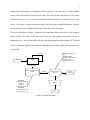
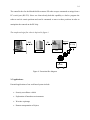
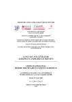
The system flowchart in figure 1 illustrates the composition and the data flow of the complete
robotic system. The flow of the data starts from the login prompt where the user has to
authenticate him / her self and ends with the robot performing the actual motion [2]. The data
itself is constituted largely of the operation commands to the robot, which during transmission,
are encoded.
Receives Data from
Client
Decodes Data
Sends Data to Robot
Sends Visual
Feedback to Client
On Fail
Login
Start
On Success
Robot Control Center
(Client)
Controls:
Inverse Kinematics
Motion
Motion of
Individual Joints
Displays:
Visual Feedback
from Camera
TCP/IP
Robot Control
Server
Robot
End
Figure 1 System Flowchart
Video
Camera
7
The most difficult criterion for most web-based telerobots to meet is that of reliability. The robot
must be available on a permanent basis while requiring minimal maintenance. While an operator
is waiting for a response from the telerobot they are unable to plan/submit the next request. To
minimize this waiting period the response time should be as small as possible [3].
Telerobots have the benefit of human cognitive and perceptual abilities, since they are operated
by a human being, they can perform more efficiently in unfamiliar and dynamic environments.
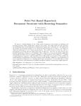
2. WWW gateway for Mitsubishi MoveMaster-EX robot
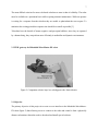
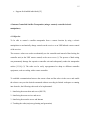
Figure 2: Companion website: http://www.bridgeport.edu/~batra/robotics
2.1 Objective
The primary objective of this project is to create a www-interface to the Mitsubishi MoveMasterEX robot (figure 2) thus allowing a user to connect to the robot and control it from a physically
distant workstation without the need to download and install special software.
8
2.2 Requirements
The following hardware and software was used for implementation:
• IBM-compatible PC
• Windows NT server 4.0 (Operating System)
• Internet Information Server 4.0 (Web Server)
• RS232 Serial port interface and cable (to connect to robot)
• Active Server Pages (enabled in IIS)
• The aspexec.dll component
• Visual Basic (to code the app to write to the serial port)
2.3 Implementation
The objective was accomplished by setting up a web-server on the PC connected directly to the
robot (through the RS232 interface) [4,5]. Users connecting to the web-server through the World
Wide Web were able to send commands to the robot by using the ASPExec component which
the Active Server Pages used to execute writetoport.exe. This executable communicated with the
robot by sending these commands through the serial port interface.
Since the Mitsubishi MoveMaster EX allows direct and inverse kinematics control directly
through the serial port, there was no need to produce and use any of the kinematics equations.
For example the robot can tolerate through the serial port a string such as “MV
100,30,0,40,50,0,-3”, where the first 5 values represent the angles in degrees for each of the
joints and the last two values represent the pitch and yaw of the end effector. The majority of the
robots nowadays do tend to have fully solved IK through their hardware, the evaluation of these
9
equations mainly being appropriate in conjunction with the dynamics equations when the robot
needs complete software control (note that the Mitsubishi Movemaster does not provide
dynamics control, providing only a set of fixed values for speed and no direct torque/actuators
control).
2.4 The ASPExec component
Description: ASPExec allows the execution of DOS and Windows apps through the Active
Server Pages (commandrobot.asp executes an executable called writetoport.exe which sends the
appropriate command to the robot through the RS-232 serial interface). The following
functionality is available through ASPExec:
property Application: Set the path (optional) and exe/com filename
property Parameters: Set the app parameters
property TimeOut: Set the timeout to wait (milliseconds). Used only for ExecuteDosApp and
ExecuteWinAppAndWait
property ShowWindow: Set whether the executing app is visible or not. Used only for
ExecuteWinAppAndWait and ExecuteWinApp
ExecuteDosApp: Executes the specified app as a DOS app and returns stdio as string
ExecuteWinAppAndWait: Execute the specified app as a Windows app and wait for the
specified timeout if exec is successful
ExecuteWinApp: Execute the specified app as a Windows app and return result code
immediately
Installation: To use this ASP component, we moved the DLL into a subdirectory (such as
\winnt\system32 for NT or \windows\system for Win95/98) and type:
10
regsvr32 aspexec.dll
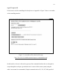
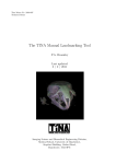
For the source code for controlling the robot please see Appendix A. Figure 3 shows a screenshot
of the controlling interface.
Figure 3: A screenshot of the main interface page
(http://216.87.101.211:8080/satcontrol/aspexec/commandrobot.asp)
In this interface, the user is allowed to type any of the commands that the robot was designed to
accept through the serial port, given that the user is aware of their correct syntax (using the
robot’s user manual is recommended). Simple commands such as GC, GO, NT, MO (specified
11
on the interface page), are easy enough to use and assure a predictable positioning of the
manipulator once the positions have been defined.
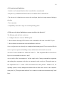
3. Remotely controlled Monitoring Vehicle
3.1 Objective
To come up with a prototype for a low-cost monitoring vehicle that can be controlled from a
remote location providing visual feedback to the remote operator.
3.2 Purpose
A small-scale prototype of the described product can demonstrate the low cost and ease of
setting up a device with an enormous number of potential applications including: security
surveillance, child monitoring, hostile territory exploration and even as a toy [6,7].
3.3 Available Resources:
The resource available to build the prototype were limited to the following list:
Hardware:
- PCs (IBM compatible)
- Mitsubishi Movemaster EX robot
- Generic RC car
12
- Radio Frequency (RF) transmitter
- Cables and connectors
- Controller box for Mistubishi Movemaster EX
- Wireless camera (for visual feedback)
Software:
- Operating Systems (Windows NT, Linux)
- Programming Languages (C++, Java, VB)
3.4 Description:
The two major implementation issues include:
1. Issuing commands to the server from a remote machine
2. Interpreting these commands and sending the appropriate signal to the car through the RF chip
Issuing Commands to the server from a remote machine
Initially we set up a web server (Internet Information Server 4.0 was the server of choice since it
is the most stable one available for a Windows NT platform)
The next step involved setting up HTML forms that allowed users to issue the appropriate
commands to the server. However, an obstacle that arose here was that these commands needed
to be sent to the RF-chip through the serial port. The web server does not have direct access to
the computer's serial port since this is a major security issue [8]. To overcome this issue, we
wrote a DLL, which allows ASP pages to run commands on the local machine. We then wrote a
simple application, which took commands to be sent to the RF chip as command-line arguments.
13
The ASPExec module then ran this application with the necessary commands as command-line
arguments, which were sent to the RF-chip.
However, the web-server/browser approach was dropped since limiting access to a single user
was not possible and a number of security problems existed. Furthermore, to be able to provide
two way communication between the client and the server (for purposes of a visual feedback), a
browser would not serve the purpose.
Hence, a java-based approach was sought. We wrote an RMI-based server which accepted a
maximum of one connection from the client software which was also written in Java. This design
also allowed IP screening and other security features. The Java Server also had direct access to
the local machine's serial port thus avoiding the need to write a separate DLL, which proved to
be a security hole by itself [9].
Interpreting these commands and sending the appropriate signal to the car through the RF chip
The major implementation issue at this point involved deciphering the commands and having the
RF chip transmit the appropriate signals. To resolve this issue, we needed an FPGA controller
which would send a unique signal to the RF chip depending on the signal it received from the
serial port. This approach was the most efficient but involved an expensive FPGA chip and
expensive software, which was unavailable to us at development time [10,11].
The alternative solution we chose was to use a robot to decipher the signals from the server and
manually manipulating buttons on the RF chip to send one of four signals (back, forward, left,
right) to the vehicle. The availability of all the resources made us pick this as our option for the
prototype.
14
The controller box for the Mitsubishi Movemaster-EX robot accepts commands as strings from a
PC's serial port (RS-232). Since our client already had this capability we had to program the
robot to teach it certain positions and send it commands to move to these positions in order to
manipulate the controls on the RF-chip.
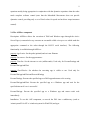
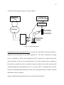
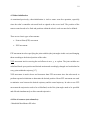
The complete design flow chart is depicted in figure 4
RMI
physical
RS-
link
server
robot
client workstation
vehicle
Figure 4. Execution flow diagram
3.5 Applications:
Potential applications of our web-based system include:
•
Security surveillance vehicle
•
Exploration of hazardous environments
•
War-time espionage
•
Remote transportation of objects
RF chip
15
•
Support for disabled individuals [12]
4. Internet Controlled Satellite Transponder (using a remotely controlled robotic
manipulator)
4.1 Objective
To be able to control a satellite transponder from a remote location by using a robotic
manipulator to mechanically change controls on the receiver or an UHF/infrared remote control
of the receiver.
The reasons a robot was used to mechanically use the controller unit instead of hard-wiring the
controller unit (or the UHF remote control) to the server were: (1) The process of hard-wiring
can permanently damage the expensive controller unit and subsequently render the transponder
useless [13,14]; (2) The robot can be easily reprogrammed to adapt to different controller
equipment, such as working with a remote controller.
To establish communication between the remote client and the robot via the server and enable
the robot to carry out the desired commands without exceeding its limited workspace or running
into obstacles, the following tasks need to be implemented:
1 - Interfacing between robot and server (RS-232)
2 - Interfacing between receiver and server
3 - Interfacing between the server and Internet
4 - Teaching the robot (trajectory planning and generation)
16
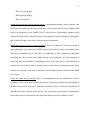
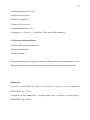
A flowchart of the proposed system is shown in figure 5.
SATELLITE
TRANSPONDER
REMOTE
PC
RECEIVER
INTERNET
Remote
Control
Video
Interface
RS-232
Robotic
Manipulat
Figure 5: System Schematics
Interfacing between the robot and the server is carried out via the RS-232 serial port, which is a
standard on the main board of any IBM-compatible PC. The robot’s controller box simply
receives commands as ASCII strings through the RS-232 connection. An important issue that
arises is that there is only one-way communication. I.E. once the computer issues commands to
the robot, the controller box does not send back a signal to indicate a successful or unsuccessful
command interpretation and application [15]. To overcome this it is important that a flawless
trajectory be planned during initialization of the robot and implemented in a manner such that
obstacles do not pose a problem.
Sample commands (among others) that can be issued to the robot include:
17
GC: Closes the gripper
GO: Opens the gripper
NT: Nest the robot
Interfacing between the receiver and the server is implemented through a special interface card
which takes the analog feed from the transponder’s receiver and converts it into a digital format
ready to be broadcast over the internet. The PC card receives a feed through a standard coaxial
cable such as that used for Cable television. The transponder can point at different ‘look-angles’
and at each look-angle it can receive feeds at numerous frequencies.
Interfacing between the server and the internet is relatively simple since it involves setting up
and configuring a web server to serve HTTP requests from clients. Security is an important issue
here and user-authentication is vital since it is undesirable to have unauthorized individuals
controlling the robot remotely and causing damage to the equipment. It is also important to
ensure that only one individual is controlling the robot at the same time. It is also important to
initialize the robot so that it starts at a position known to the software. Initialization also involves
defining key positions in the robot’s workspace and defining trajectories that the robot should
travel along.
Lastly, the robot must be ‘taught’ about its surroundings and the environment that it will be
operating in. This can be done by fixing the position of the remote control unit and defining its
position relative to that of the robot. This allows the robot to ‘know’ where the controller unit is
and where particular controls on the unit are. The robot must be nested prior to operation to
ensure that it always starts from the same point thus allowing error-free software control.
18
4.2 Constraints and limitations:
- Limited set of commands that the robot’s controller box can understand
- Only one-way communication between the server and the robot’s controller box
- The web server’s clients have no access to the serial port, which is the only means of talking to
the robot
- Time constraints
- Compatibility issues force usage of a certain operating system
4.3 How were the above limitations overcome to achieve the objective?
The following tasks had to be carried out:
1 - Configure the server-to-server HTTP requests
2 - Write software allowing HTTP clients to issue commands to the robot via the RS-232 port
3 - Write software to initialize the robot and define the work area
Server configuration was relatively less complicated and setting up an NT server with an IIS web
server to process requests and enabling security authentication and control was smooth.
An ActiveX control needed to be written in Visual C++. This component allows Active Server
Pages to run executables on the server itself.
An executable called ‘writetoport.exe’ did the simple task of taking command-line arguments
and sending these arguments to the robot as commands via the serial port. This application was
first implemented in C++ under a DOS environment but when ported to Windows NT, the
operating system’s security management features did not allow direct access to the computer's
serial ports [16]. This application needed to be re-written in a windows environment using Visual
Basic.
19
4.3 Robot initialization
As mentioned previously, robot-initialization is vital to ensure error-free operation, especially
since the robot’s controller unit sends back no signals to the server itself. The position of the
remote control needs to be fixed and positions within the robot’s work area need to be defined.
There are two basic types of movements:
•
Point to Point (PTP) movement
•
XYZ movement
PTP movement involves specifying the joint variables (the joint angles in this case) and changing
them according to the desired position of the robot.
XYZ movement involves moving the end-effector in an x, y, or z plane. The joint variables are
calculated based upon position and desired motion and accordingly changed and recalculated at
every point within the trajectory [17].
XYZ movement is much slower and inaccurate than PTP movement since the robot needs to
perform repeated calculations to determine the desired position. Hence PTP movement was used
to minimize error between the desired trajectory and the actual trajectory. In order to use PTP
movement the trajectories need to be well-defined; each of the joint angles need to be specified
and effected simultaneously to allow smooth trajectories.
4.4 List of resources (not exhaustive):
- Mitsubishi MoveMaster EX robot
20
- Satellite transponder and receiver
- Interface card for receiver
- IBM-PC or compatible
- Windows NT 4.0 (server)
- Internet Information Server 4.0
- Languages: C++, Visual C++, Visual Basic, VBscript (for ASP technology)
4.5 Advantages and potential uses:
- Remote satellite feed for internet users
- Remote communication
- Distance learning
The project demonstrates the synergy created by combining robotic and computing power. On a
larger scale this concept can be ported to pragmatic and useful web applications using robots.
Bibliography
[1] Korein, J., and Badler, N., Temporal Anti-Aliasing in Computer Generated Animation,
SIGGRAPH'83, pp. 377-388.
[2] Potmesil, M. and Chadkravarty, I., Modeling Motion Blur in Computer Generated Images,
SIGGRAPH'83, pp. 389-400.
21
[3] Cook, R., Porter, T. and Carpenter, L., Distributed Ray Tracing, SIGGRAPH'84, pp. 137146.
[4] Wilhelms, J., Toward Automatic Motion Control, IEEE Computer Graphics and Applications.
V7 #4, April 1987, pp. 11-22.
[5] Zeltser, D., Toward an Integrated View of 3-D Computer Animation, The Visual Computer,
VI #4, 1985. pp. 249-259.
[6] E. Grosso, G. Sandini, and C. Frigato. Extraction of 3D information and volumetric
uncertainty from multiple stereo images. In Proceedings of the 8th European Conference on
Artificial Intelligence, pages 683-688, August 1988.
[7] P. Hebert, D. Laurendeau, and D. Poussart. Scene reconstruction and description: geometric
primitive extraction from multiple viewed scattered data. In Proceedings of IEEE Conference on
Computer Vision and Pattern Recognition, pages 286-292, June 1993.
[8] A. Hilton, A.J. Toddart, J. Illingworth, and T. Windeatt. Reliable surface reconstruction from
multiple range images. In Fourth European Conference on Computer Vision, volume I, pages
117-126, April 1996.
[9] Tsai-Hong Hong and M. O. Shneier. Describing a robot's workspace using a sequence of
views from a moving camera. IEEE Transactions on Pattern Analysis and Machine Intelligence,
7(6):721-726, November 1985.
[10] H. Hoppe, T. DeRose, T. Duchamp, J. McDonald, and W. Stuetzle. Surface reconstruction
from unorganized points. In Computer Graphics (SIGGRAPH '92 Proceedings), volume 26,
pages 71-78, July 1992.
[11] V. Krishnamurthy and M. Levoy. Fitting smooth surfaces to dense polygon meshes. In these
proceedings.
22
[12] P. Lacroute and M. Levoy. Fast volume rendering using a shear-warp factorization of the
viewing transformation. In Proceedings of SIGGRAPH '94 (Orlando, FL, July 24-29, 1994),
pages 451-458. ACM Press, July 1994.
[13] A. Li and G. Crebbin. Octree encoding of objects from range images. Pattern Recognition,
27(5):727-739, May 1994.
[14] W.E. Lorensen and H. E. Cline. Marching cubes: A high resolution 3D surface construction
algorithm. In Computer Graphics (SIGGRAPH '87 Proceedings), volume 21, pages 163-169,
July 1987.
[15] S-F Chang, J.R Smith, H.J. Meng, H. Wang, and D. Zhong. Finding images/video in large
archives. D-Lib Magazine, February 1997.
[16] Stavros Christodoulakis and Peter Triantafillou. Research and development issues for largescale multimedia information systems. ACM Computing Surveys, Dec 1995.
[17] M.G. Christel, D.B. Winkler, and C.R. Taylor. Multimedia abstraction for a digital video
library. In ACM Digital Libraries '97, pages 21-29, Philadelphia, PA, 1997.
Appendices
Appendix A: Source code for the commandrobot.asp page
<HTML>
<head><title>ASPExec Test (ExecuteWinApp)</title><head>
<body bgcolor=white text=black>
<blockquote>
<H3>Robotics Write to Port Application (Univ. of Bridgeport, Cpe 360)</H3>
<H4>Puneet Batra ©2000</H4>
23
<FORM ACTION="commandrobot.asp">
<INPUT TYPE=TEXT SIZE=20 NAME="command">
<INPUT TYPE=SUBMIT VALUE="Execute Command">
</FORM>
<%
cmd = request.querystring("command")
Set Executor = Server.CreateObject("ASPExec.Execute")
Executor.Application = "c:\robotics\writetoport.exe"
Executor.Parameters = cmd
Executor.ShowWindow = True
Response.Write "Attempting to execute " & Executor.Application & " " & Executor.Parameters &
"<br>"
strResult = Executor.ExecuteWinApp
Response.Write "The result of this call was: " & strResult
%>
<BR><BR><BR>
<HR ALIGN=LEFT WIDTH=50%>
<FORM ACTION="commandrobot.asp">
<INPUT TYPE=HIDDEN SIZE=20 NAME="command" VALUE="NT">
<INPUT TYPE=SUBMIT VALUE="Nest Robot">
</FORM>
<FORM ACTION="commandrobot.asp">
<INPUT TYPE=HIDDEN SIZE=20 NAME="command" VALUE="MO 9, C">
<INPUT TYPE=SUBMIT VALUE="Raise clear of obstacles"> <FONT COLOR=RED> <=====PRESS THIS BUTTON
BEFORE EACH MOVE !</FONT>
</FORM>
<TABLE>
<TR>
<TD>
</FORM>
<FORM ACTION="commandrobot.asp">
<INPUT TYPE=HIDDEN SIZE=20 NAME="command" VALUE="MO 1, C">
<INPUT TYPE=SUBMIT VALUE="Button 1">
</FORM>
24
</TD>
<TD>
<FORM ACTION="commandrobot.asp">
<INPUT TYPE=HIDDEN SIZE=20 NAME="command" VALUE="MO 2, C">
<INPUT TYPE=SUBMIT VALUE="Button 2">
</FORM>
</TD>
<TD>
<FORM ACTION="commandrobot.asp">
<INPUT TYPE=HIDDEN SIZE=20 NAME="command" VALUE="MO 3, C">
<INPUT TYPE=SUBMIT VALUE="Button 3">
</FORM>
</TD>
<TD>
<FORM ACTION="commandrobot.asp">
<INPUT TYPE=HIDDEN SIZE=20 NAME="command" VALUE="MO 4, C">
<INPUT TYPE=SUBMIT VALUE="Button 4">
</FORM>
</TD>
</TR>
</TABLE>
<HR ALIGN=LEFT WIDTH=50%>
<SMALL>
Mitsubishi MOVEMASTER-EX commands only (sample commands follow)
<BR><BR>
GC: Gripper Close<BR>
GO: Gripper Open<BR>
NT: Nest<BR>
MO #, C/O: Move to Position number (#) with gripper closed (C) or open (O)
</SMALL>
</blockquote>
</body>
</html>