1
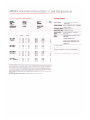
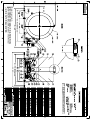
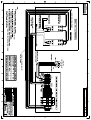
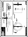
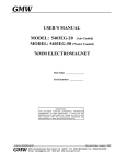
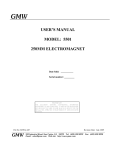
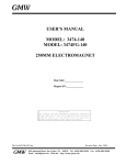
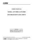
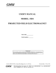
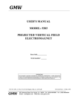
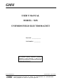
GMW
USER’S MANUAL
MODEL: 5451
UNIFORM FIELD ELECTROMAGNET
Date Sold: _______________
Serial number: ___________
PROPRIETARY
THIS DOCUMENT CONTAINS CONFIDENTIAL INFORMATION
PROPRIETARY TO GMW ASSOCIATES.
IT MUST NOT BE
REPRODUCED OR DISCLOSED TO OTHERS OR USED IN ANY WAY
EXCECPT FOR THE INSTALLATION, OPERATION OR MAINTENANCE
OF GMW ASSOCIATES PRODUCTS.
File No: M5451d.407
GMW
955 Industrial Road, San Carlos, CA 94070 Tel: (650) 802-8292
Email: [email protected] Web site: http://www.gmw.com
Revision Date: April 6, 2004
Fax: (650) 802-8298
TABLE OF CONTENTS
SPECIFICATIONS
5451
Table 1 Model 5451 General Specifications
Table 2 Model 5451 Electrical and Water Connections
Section 1
WARNINGS [ Refer to this section before operation of Electromagnet ]
Section 2
INSTALLATION
Unpacking Instructions
Siting Considerations
Electrical Circuit
Interlocks
Cooling
Section 3
OPERATION
General
Calibration
Field Control Operation
Section 4
MAINTENANCE
Section 5
STANDARD OPTIONS
Section 6
CUSTOM OPTIONS
Section 7
EXCITATION CURVES
Section 8
TEST DATA
Section 9
DRAWINGS
Elmwood 3450 Thermostats
Drawing 11910040 Uniform Field Electromagnet General Assembly
Drawing 11900920 Uniform Field Electromagnet Electrical Assembly
Drawing 13900320 Uniform Field Electromagnet Electrical Wiring
Drawing 11901720 Uniform Field Electromagnet Probe Mount [Radial]
Drawing 11901730 Uniform Field Electromagnet Probe Mount [Axial]
Drawing 11901252 Uniform Field Electromagnet Probe Mount General Assembly
Section 10
Section 1
SPECIFICATIONS
Table 1. Model 5451 Specifications
Magnet Field @ max power (X,Y,Z=0.0)
54 mT (540 Gauss)
Magnet Inside Diameter:
300 mm (11.8 inch)
Magnet Length:
338 mm (13.3 inch)
Coils (series connection)
coil Resistance (20°C)
max resistance (hot)*
max power (air cooled)
max power (water cooled)
Self Inductance
Calibration Factor (field versus current)
0.32 Ohm
0.37 Ohm
25A/9.3V (0.23 kW)
70A/25V (1.81 kW)
35mH
0.77mT/A
Field Uniformity ∆B/B
less than ±200ppm over a 30mm sphere
Water Cooling (18°C)
1.0 bar (15 psid), 2 liters/m (0.5 US gpm)
Overtemperature Interlock
Dimensions
Mass
Elmwood 3450G thermal sensor part number
3450G 611-1 L50C 89/16 mounted on each coil
and wired in series. Contact rating 120Vac,0.5A.
Closed below 50°C.
Drawing 11910040
500 mm W x 552 mm D x 427 mm H
(19.7 inch W x 21.7 inch D x 16.8 inch H)
100 kg (220 lb)
*CAUTION - The value of maximum coil resistance given should not be exceeded. At this
resistance the coils are at maximum safe temperature for continuous operation.
1-1
Section 1
SPECIFICATIONS
Table 2. Model 5451 Electrical and Water Connections
DC Current (as seen from the front refer to Drawing 11910040)
Left hand terminal
Negative
Right hand terminal
Positive
Ground
An M4 screw (Part 14 on drawing 11910040) is provided near the coil current connections to enable the
magnet frame to be grounded according to local safety regulations. It is normally appropriate to connect the
magnet frame to the power supply ground.
Interlocks (refer to Drawing 11910040)
Overtemperature thermostats (part 9 on Drawing 11910040) are installed on each coil cooling plate. These
are normally closed for temperatures of less than 50°C. All six thermostats are wired in series. The magnet
power supply should be connected so that if any thermostat opens (goes overtemperature) the power
supply current will be set to zero. User connections are made directly to the thermostat terminals.
Water (refer to Drawing 11910040)
outlet
1/4 inch NPT
inlet
1/4 inch NPT
(mating couplings for 6.0 mm (1/4 inch) ID hose are provided)
CAUTION - Ensure that the high current connections are tight. Loose connections may lead to oxidation
and overheating. The field stability may be degraded and the current terminations damaged.
1-2
Section 2
WARNINGS
REFER TO WARNINGS BELOW BEFORE OPERATING ELECTROMAGNET
1
Personnel Safety
The Model 5451 is a unshielded electromagnet. In operation the magnet fringing field can be in excess
of 0.5mT(5G). This can cause malfunctioning of heart pacemakers and other medical implants. We
recommend that the fringing field should be mapped and warning signs be placed outside the 0.5mT
(5G) contour. Entry to this region of higher field should be restricted to qualified personnel.
2
Ferromagnetic Objects
During operation the magnet exerts strong magnetic attraction towards ferromagnetic objects in the near
vicinity. Loose objects can be accelerated to sufficient velocity to cause severe personnel injury or
damage to the coils. Keep ferromagnetic tools clear!
3
Arcing
This magnet stores considerable energy in its field during operation. Do not disconnect any current lead
while under load or the magnetic field energy will be discharged across the interruption causing
hazardous arcing.
4
Coil Hot Resistance
Do not exceed the maximum coil hot resistance given in the specifications or coil overheating and
possible damage may occur.
5
Interlocks
These should always be connected if the magnet is operated unattended, to avoid the possibility of coil
overheating caused by excessive power dissipation or inadequate cooling.
6
Watches, Credit Cards, and Magnetic Disks
Do not move magnetically sensitive items into the close vicinity of the magnet. Even some anti-magnetic
watches can be damaged when placed in close proximity to the magnet during operation. Credit cards,
and magnetic disks are affected by magnetic fields as low as 0.5mT (5G).
2-1
Section 3
INSTALLATION
Caution: This is a heavy system. All movement, lifting and installation of the 5451 Electromagnet must be
under the supervision of an experienced person to prevent the possibility of serious injury or damage to the
Electromagnet and associated equipment.
Unpacking Instructions and Damage Inspection
To unpack the electromagnet please use the following procedure.
1. First remove all of the "Hex Head Screws" located at the lower edge of all the side panels of the "Crate
Top Cover".
2. Gently rock the "Crate Top Cover" to work it loose from the shipping crate base.
3. Use one person on each side of the shipping crate, grip the side panels of the Crate Top Cover. Lift
"Crate Top Cover" high enough to clear top of electromagnet, walk cover sideways to clear area and
place on floor.
4. Inspect the magnet to ensure that no damage has occurred to the magnet in shipment. If damage is
evident report the damage in detail to the shipper for claim and simultaneously notify GMW in case
assessment of the damage must be made. If no damage is found proceed with magnet unpacking and
installation.
With suitable lifting equipment (eg 150kg 330lb minimum safe lifting rating) lift magnet clear of the
shipping crate.
TAKE CARE THAT NO SIDE LOADS ARE PUT ON THE MAGNET MOUNTING LEGS, OR
DAMAGE MAY OCCUR.
Siting Considerations
The Model 5451 has no magnetic shielding. Magnetic material in the vicinity of the magnet will
modify the magnitude and uniformity of the central region magnetic field. As a general rule avoid
magnetic material closer than approximately 1 meter of the central region.
Background fields such as the geomagnetic field and alternating field from 60Hz power sources are
unshielded by the magnet and will add vectorially to the field produced by the magnet. If possible these
background fields should be measured and their effects evaluated before the Model 5451 magnet is
installed. It may be necessary to orient the Model 5451 axis to minimize the effects of external fields, to
resite ac power sources or to install suitable magnetic shielding.
3-1
Section 3
INSTALLATION
Electrical Circuit
Never connect or remove cables from the magnet with the power supply connected. The stored energy in
the magnet can cause arcing resulting in severe injury to personnel or equipment damage.
The magnet has two coils which are connected in series, (Refer to drawing 11910040). The power supply
cables should be connected directly to the dc current terminals marked + and -. Recommended current
cable for the 5451 is stranded copper of 16mm² cross section (4 AWG). Because the magnet stores a
significant amount of energy in its magnetic field, special care should be taken to insure that the current
terminations are secure and cannot work loose in operation. Local heating at the terminations can cause
rapid oxidation leading to a high contact resistance and high power dissipation at the terminals. If left
unattended this can cause enough local heating to damage the terminals and the coils.
The 5451 Interlocks
The Model 5451 has six thermostats, Elmwood 3450G Part Number 3450G611-1 L50C 89/16. They are
located on the coil cooling plates and wired in series. User connections are made directly to the thermostat
terminals.
Cooling
The Model 5451 can be operated to an average coil temperature of 70°C. Assuming an ambient
laboratory temperature of 20°C and a temperature coefficient of resistivity for copper of 0.0039/°C, the hot
resistance of the coil should not exceed 20% more than the ambient temperature "cold" resistance. The coil
thermal thermostats will open when any coil cooling plate temperature exceeds approximately 50°C . Clean,
cool (16°C - 20°C) water at 2 l/min and 1 bar (15 psid) should be used to cool the 5451 magnet.
The cooling copper tubes are electrically isolated from the coils to avoid electrochemical corrosion. A 50
micron filter should be placed before the input to the magnet to trap particulates.
For continuous operation of the magnet it may be appropriate to use a recirculating chiller to reduce water
and drainage costs. The chiller capacity will depend on whether cooling is required for the magnet alone or
magnet and power supply. For the Model 5451 Electromagnet alone a suitable chiller is the Bay Voltex
Model: MC-50 Chiller. For the 5451 and 858-70A/30V Power Supply the required Chiller is Bay Voltex
Model: MC-100. Use distilled or deionized water with a biocide to prevent bacterial growth and corrosion.
Do not use corrosion inhibitors in high quality electrical systems since the water conductivity is increased
which can result in increased leakage currents and electrochemical corrosion.
At currents of approximately 25A and below the Model 5451 can be operated safely without water
cooling. However the coil temperature will vary with the power dissipation. This results in dimensional
changes of the magnet and air cooling is not suitable when high field stability is required.
3-2
Section 3
INSTALLATION
Cooling - continued
Freon, oil, ethylene glycol or other cooling mediums can be used. The flow required will be approximately
inversely proportional to their specific heats. An experimental determination of the flow and pressure
required will be necessary.
Avoid cooling the magnet below the dew point of the ambient air. Condensation may cause electrical shorts
and corrosion.
During operation the resistance can be checked using a voltmeter across each coil. The voltage will rise to a
constant value once thermal equilibrium has been reached. If it is desired to save water, the flow can be
reduced until the hot resistance is approached. NOTE: This adjustment must be made slowly enough to
allow for the thermal inertia of the coils.
3-3
Section 4
OPERATION
General
The magnet operates as a conventional electromagnet.
1. Adjust the cooling water flow to about 2 liters/min (0.5 USgpm). For operation at less than maximum
power the water flow may be correspondingly reduced. Note that the inlet water temperature will
determine the actual flow rate required. The above specified flow rates were determined with a water
inlet temperature of approximately 18°C.
2. Turn on the power supply and increase the current until the desired field is reached.
Calibration
The Calibration factor may be used to estimate the field in the air gap to within one percent. More accurate
field determination may be obtained by deriving experimentally a calibration curve.
Greater precision in setting up the calibration curve will be achieved with the use of a digital gaussmeter and
by making a numerical table. This table used with an interpolation routine will eliminate the error associated
with reading a graph.
In any event, three points need to be remembered:
1. A calibration curve or table is only as good as the precision employed in generating it.
2. The field is defined only at the point it is measured. It will generally be different at a different point in the
magnet. For example, the induction curves refer to the field on the axis and at the center of the coil pair.
3. The field is most directly a function of the current in the magnet coils. Voltage across the coils is not a
good measure of field since the electrical resistance of the coils depends on the temperature (about
0.4% per degree Celsius).
Field Control Operation
The necessity to use calibration curves can be avoided by using a field controller to sense the magnetic field
and provide a corresponding power supply control signal through the power supply programming inputs.
Contact GMW for suitable instrumentation.
4-1
Section 5
MAINTENANCE
Check the cooling water circuit to ensure the water is clean and free of debris and bacterial growth. Ensure
the in-line water filter is clean.
5-1
Section 6
STANDARD OPTIONS
Section 7
CUSTOM OPTIONS
Section 8
EXCITATION CURVES
Section 9
TEST DATA
GMW MODEL 5451 ELECTROMAGNET
Ref: Drg 11910040
Serial No.: 001
File No S5451ubc.007
Magnet shimmed with 0.030"
Date:
10/5/1994
Operator: Robert Yaus
Setup II
Earth-Field:
B(x): +0.1283G
B(y): -0.2026G
B(z): -0.4000G
Probe
Current:
X VARIATION
B(NMR) [Gauss]
POSITION [mm]
x-Axis
y-Axis
z-Axis
0
0
0
-20
0
0
-15
0
0
-10
0
0
-5
0
0
0
0
0
5
0
0
10
0
0
15
0
0
20
0
0
0
0
0
60A
U(NMR) [mV]
467.001
466.936
466.978
466.998
467.005
467.001
466.989
466.965
466.924
466.867
467.001
-90
-90
-90
-90
-90
-90
-90
-90
-80
-80
-90
Uniformity Plot
0.0005
0.0004
0.0003
0.0002
∆B/B
0.0001
0
-0.0001
-0.0002
-0.0003
-0.0004
-0.0005
-20
-15
-10
-5
0
Position [mm]
5
10
15
20
GMW MODEL 5451 ELECTROMAGNET
Ref: Drg 11910040
Serial No.: 001
File No S5451ubd.007
Magnet shimmed with 0.030"
Date:
10/5/1994
Operator: Robert Yaus
Setup II
Earth-Field:
B(x): +0.1283G
B(y): -0.2026G
B(z): -0.4000G
Probe
Current:
Y VARIATION
B(NMR) [Gauss]
POSITION [mm]
x-Axis
y-Axis
z-Axis
0
0
0
0
-20
0
0
-15
0
0
-10
0
0
-5
0
0
0
0
0
5
0
0
10
0
0
15
0
0
20
0
0
0
0
60A
U(NMR) [mV]
467.003
467.040
467.045
467.030
467.012
467.003
467.013
467.043
467.083
467.123
467.003
-90
-90
-90
-90
-90
-90
-90
-90
-90
-90
-90
Uniformity Plot
0.0005
0.0004
0.0003
0.0002
∆B/B
0.0001
0
-0.0001
-0.0002
-0.0003
-0.0004
-0.0005
-20
-15
-10
-5
0
Position [mm]
5
10
15
20
GMW MODEL 5451 ELECTROMAGNET
Ref: Drg 11910040
Serial No.: 001
File No S5451ube.007
Magnet shimmed with 0.030"
Date:
10/5/1994
Operator: Robert Yaus
Setup II
Earth-Field:
B(x): +0.1283G
B(y): -0.2026G
B(z): -0.4000G
Probe
Current:
Z VARIATION
B(NMR) [Gauss]
POSITION [mm]
x-Axis
y-Axis
z-Axis
0
0
0
0
0
-20
0
0
-15
0
0
-10
0
0
-5
0
0
0
0
0
5
0
0
10
0
0
15
0
0
20
0
0
0
60A
U(NMR) [mV]
467.003
466.880
466.938
466.977
466.994
467.003
467.004
466.993
466.973
466.937
467.003
-90
-90
-90
-90
-90
-90
-90
-90
-90
-90
-90
Uniformity Plot
0.0005
0.0004
0.0003
0.0002
∆B/B
0.0001
0
-0.0001
-0.0002
-0.0003
-0.0004
-0.0005
-20
-15
-10
-5
0
Position [mm]
5
10
15
20
Section 10
DRAWINGS