1
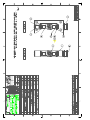
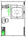
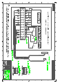
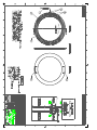
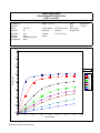
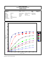
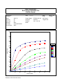
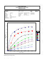
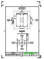
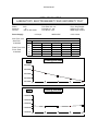
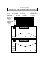
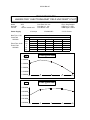
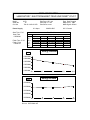
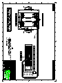
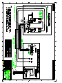
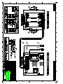
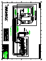
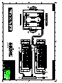
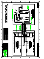
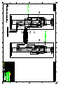
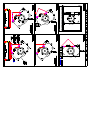
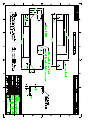
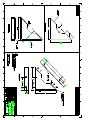
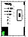
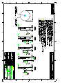
GMW
USER’S MANUAL
MODEL: 3473-50
MODEL: 3473-70
150MM ELECTROMAGNET
Date Sold: _______________
Serial number: ___________
PROPRIETARY
THIS
DOCUMENT
CONTAINS
CONFIDENTIAL
INFORMATION
PROPRIETARY TO GMW ASSOCIATES. IT MUST NOT BE REPRODUCED
OR DISCLOSED TO OTHERS OR USED IN ANY WAY EXCECPT FOR THE
INSTALLATION, OPERATION OR MAINTENANCE OF GMW ASSOCIATES
PRODUCTS.
File No: M3473g.407
GMW
Revision Date: March 22, 2000
955 Industrial Road, San Carlos, CA 94070 Tel: (650) 802-8292
Email: [email protected] Web site: http://www.gmw.com
Fax: (650) 802-8298
TABLE OF CONTENTS
SPECIFICATIONS
Table 1 Model 3473-50 General Specifications
Table 1 Model 3473-70 General Specifications
Table 2 Model 3473-50/3473-70 Electrical and Water Connections
Section 1
WARNINGS [ Refer to this section before operation of Electromagnet ]
Section 2
INSTALLATION
Unpacking Instructions
Mounting Position
Pole Selection and Installation
Electrical Circuit
Interlocks
Cooling
Section 3
OPERATION
General
Calibration
Field Control Operation
Section 4
MAINTENANCE
Section 5
STANDARD OPTIONS
Motorized Rotating Drive
Bias Coils
Pole Spacer [for 100mm Pole Caps]
Pole Spacer [for 150mm Pole Caps]
Probe Holder
Section 6
CUSTOM OPTIONS
Section 7
EXCITATION CURVES
Section 8
TEST DATA
Section 9
DRAWINGS
Elmwood 3450 Thermostats
Imo Gems Series Flow Switch
Section 10
Continued...
DRAWINGS
Drawing 11801281 3473-50 Electromagnet General Assembly
Drawing 11801282 3473-70 Electromagnet General Assembly
Drawing 11900710 3473-50/P62-4050A Electromagnet Electrical Assembly
Drawing 13900210 3473-50/P62-4050A Electromagnet Electrical Wiring
Drawing 11900700 3473-70/P63-60110A Electromagnet Electrical Assembly
Drawing 13900200 3473-70/P63-60110A Electromagnet Electrical Wiring
Drawing 11900220 3473-70/DF858 Electromagnet Electrical Assembly
Drawing 13900100 3473-70/DF858 Electromagnet Electrical Wiring
Drawing 11900230 3473-50/BOP20-40 Electromagnet Electrical Assembly
Drawing 13900080 3473-50/BOP20-40 Electromagnet Electrical Wiring
Drawing 13900090 3473-50/BOP20-20/20-20 Power Supply Electrical Wiring
Drawing 11900110 Electromagnet Assembly Sequence to Rolling/Rotating Base
Drawing 11803230 Electromagnet Assembly to Rolling/Rotating Base (45° Mtg)
Drawing 11803200 Electromagnet Assembly to Rolling Base (45° Mtg)
Drawing 11803210 Electromagnet Assembly to Rotating Base (45° Mtg)
Drawing 11900090 Electromagnet Assembly to Rolling/Rotating Base (Horz Mtg)
Drawing 11900080 Electromagnet Assembly to Rolling Base (Horz Mtg)
Drawing 11900100 Electromagnet Assembly to Rotating Base (Horz Mtg)
Drawing 11803430 Electromagnet Rolling/Rotating Base Assembly
Drawing 11803170 Electromagnet Rolling Base Assembly
Drawing 11802090 Electromagnet Rotating Base Assembly
Drawing 11803250 Electromagnet Assembly to Vertical Mount
Drawing 11900070 Electromagnet Assembly to Horizontal Mount
Drawing 17803180 Electromagnet Vertical Mount Bracket
Drawing 17900170 Electromagnet Horizontal Mount Bracket
Drawing 17800520 Electromagnet 45 Degree Mount Bracket
Drawing 18900020 Electromagnet Tool Kit
Drawing 17801350 Pole Cap (150, 100, 75, 50, 25mm)
Drawing 18800361 Shipping Crate Assembly
Drawing 18800410 Packing Box Pole Cap Pair
Section 1
SPECIFICATIONS
Table 1. Model 3473-50 Specifications
Pole Diameter:
Pole Gap:
Standard Pole Caps:
Coils (series connection)
coil resistance (20°C)
max resistance (hot)*
max power (air)
max power (water)
150mm (6 inch)
0 - 127mm (0 to 5 inch)
150mm (6 inch) cylindrical
100mm (4 inch) tapered
75mm (3 inch) tapered
50mm (2 inch) tapered
25mm (1 inch) tapered
0.72 Ohm
0.87 Ohm
20A/17V (0.5kW)
50A/44V (2.2kW)
Self Inductance
Water Cooling (18°C)
Overtemperature Interlock
Water Flow Interlock
.
Dimensions
Weight
3 liters/m (0.8 US gpm) 0.8 bar (12 psid)
Elmwood 3450G thermostat part number
3450G 611-1 L50C 89/16 mounted on each coil
and wired in series. Contact rating 120Vac,0.5A.
Closed below 50°C.
Imo/Gems flow switch part number FS927
Part No.70823 mounted on outlet side of water circuit.
Contact rating 0.17A/120Vac (non inductive).
Set to open at a flow of less than 2.5 l/min (0.7 USgpm)
Drawing 11801281
686mm W x 405mm D x 570mm H
(27.0 inch W x 16.0 inch D x 22.4 inch H)
600 kg (1320 lb)
*CAUTION - The value of maximum coil resistance given should not be exceeded. At this
resistance the coils are at maximum safe temperature for continuous operation.
1-1
Section 1
SPECIFICATIONS
Table 1. Model 3473-70 Specifications
Pole Diameter
Pole Gap
Standard Pole Caps
Coils (series connection)
coil resistance (20°C)
max resistance (hot)*
max power (air)
max power (water)
150mm (6 inch)
0 - 96mm (0 to 3.8 inch)
150mm (6 inch) cylindrical
100mm (4 inch) tapered
75mm (3 inch) tapered
50mm (2 inch) tapered
25mm (1 inch) tapered
0.72 Ohm
0.87 Ohm
20A/17V (0.5kW)
70A/59V (4.1kW)
Self Inductance
Water Cooling (18°C)
Overtemperature Interlock
Water Flow Interlock
Dimensions
Weight
6 liters/m (1.6 US gpm) 2.0 bar (30 psid)
Elmwood 3450G thermostat part number
3450G 611-1 L50C 89/16 mounted on each coil
and wired in series. Contact rating 120Vac,0.5A.
Closed below 50°C.
Imo/Gems flow switch part number FS927
Part No.70825 mounted on outlet side of water circuit.
Contact rating 0.17A/120Vac (non inductive).
Set to open at a flow of less than 4 l/min (1.1 USgpm).
Drawing 11801282
686mm W x 405mm D x 570mm H
(27.0 inch W x 16.0 inch D x 22.4 inch H)
610 kg (1340 lb.)
*CAUTION - The value of maximum coil resistance given should not be exceeded. At this
resistance the coils are at maximum safe temperature for continuous operation.
1-2
Section 1
SPECIFICATIONS
Table 2. Model 3473-50/3473-70 Electrical and Water Connections
DC Current (as seen from the rear refer to Drawing 11801281/2)
Right hand terminal:
Negative
Left hand terminal:
Positive
Ground
An M6 screw (Item 40 on drawing 11801281/2 ) is provided near the Interlock Block connections to
enable the magnet frame to be grounded according to local safety regulations. It is normally
appropriate to connect the magnet frame to the power supply ground.
Interlocks (refer to Drawing 11801281/2)
1
Water flow
2
Water flow
3
Temperature
4
Temperature
5
No connection
6
No connection
7
Signal ground
8
Spare (No connection)
Water (refer to Drawing 11801281/2)
Outlet:
¼ inch NPT
Inlet:
¼ inch NPT
(mating couplings for ¼ inch hose provided)
CAUTION - Ensure that the high current connections are tight. Loose connections may lead to
oxidation and overheating. The field stability may be degraded and the current terminations damaged.
2-2
Section 2
WARNINGS
REFER TO WARNINGS BELOW BEFORE OPERATING ELECTROMAGNET
1
Personnel Safety
In operation the magnet fringing field is in excess of 0.5mT (5G). This can cause malfunctioning
of heart pacemakers and other medical implants. We recommend that the fringing field should be
mapped and warning signs be placed outside the 0.5mT (5G) contour. Entry to this region should
be restricted to qualified personnel
2
Ferromagnetic Objects
During operation the magnet exerts strong magnetic attraction towards ferromagnetic objects in the
near vicinity of its pole gap or coils. Loose objects can be accelerated to sufficient velocity to
cause severe personnel injury or damage to the coils or precision pole faces if struck. Keep
ferromagnetic tools clear!
3
Arcing
This magnet stores considerable energy in its field during operation. Do not disconnect any current
lead while under load or the magnetic field energy will be discharged across the interruption
causing hazardous arcing.
4
Coil Hot Resistance
Do not exceed the maximum coil hot resistance given in the specifications or coil overheating and
possible damage may occur.
5
Interlocks
These should always be connected if the magnet is operated unattended, to avoid the possibility of
coil overheating caused by excessive power dissipation or inadequate cooling.
6
Watches, Credit Cards, and Magnetic Disks
Do not move magnetically sensitive items into the close vicinity of the magnet. Even some antimagnetic watches can be damaged when placed in close proximity to the pole gaps during
operation. Credit cards, and magnetic disks are affected by magnetic fields as low as 0.5mT (5G).
Depending on the previous operating field and the pole gap, the remanent field in the gap can be in
excess of 50G (5mT) with the magnet power supply off or disconnected.
2-1
Section 3
INSTALLATION
Caution: This is a heavy system. All movement, lifting and installation of the 3473 Electromagnet
must be under the supervision of an experienced person to prevent the possibility of serious injury or
damage to the Electromagnet and associated equipment.
Unpacking Instructions and Damage Inspection
To unpack the electromagnet please use the following procedure (Refer to Drawing 18800361).
1. First remove all of the "Hex Head Screws" located at the lower edge of all the side panels of the
"Crate Top Cover".
2. Gently rock the "Crate Top Cover" to work it loose from the shipping crate base.
3. Use one person on each side of the shipping crate grip the side panels of the Crate Top Cover. Lift
"Crate Top Cover" high enough to clear top of electromagnet, walk cover sideways to clear area
and place on floor.
4. Inspect the magnet to ensure that no damage has occurred to the magnet in shipment. If damage is
evident report the damage in detail to the shipper for claim and simultaneously notify GMW in
case assessment of the damage must be made. If no damage is found proceed with magnet
unpacking and installation.
5. Remove the M16 Hex Bolts that secure the magnet to the steel shipping angle brackets.
6. Remove the hex lag bolts that secure the steel "shipping angle brackets" to shipping crate base, and
remove shipping angle brackets.
7. Install M16 lifting eye and washer to top of magnet yoke, screw down firmly.
8. The magnet is now prepared for final installation, follow the appropriate following procedure to
install to 45°, vertical or direct mounting.
Direct Mounting
1. With suitable lifting equipment (e.g. 900kg (2000 lb.) minimum safe lifting rating), lift magnet
50mm (2") clear of shipping crate base.
2. Slide shipping crate base clear.
3. Lower magnet to 50mm (2") above floor.
4. Move magnet to final location and secure using the steel shipping angle brackets. The brackets can
be modified to suit installation space needs.
5.
Rolling or Rolling/Rotating Base Mounting (refer to Drawing 11900110)
Caution do not attempt to move magnet and rolling base or rolling/rotating base until the magnet has
been firmly bolted down to the base (refer to figure 6).
1. To mount on rolling base or rolling/rotating base lift magnet from BOTH FRONT EYEBOLTS
high enough to clear top of base (refer to figure 5).
2. Slide rolling base or rolling/rotating base underneath, lower magnet to 12mm (0.5") above base
top surface (refer to figure 5).
3. Position rolling base or rolling/rotating base so the tapped hole in the base are aligned with the 45°
mounting bracket hole (refer to figure 5).
4. Lower magnet onto rolling base or rolling/rotating base assembly (refer to figure 5).
5. Secure magnet and 45° mounting assembly to rolling base or rolling/rotating base with M16 x 25
long Hex Head Bolts (refer to figure 6).
6. Move magnet and rolling base or rolling/rotating base to desired location.
Continued….
3-1
Section 3
INSTALLATION
Rolling or Rolling/Rotating Base Mounting (continued)
7. Screw down the four support legs located on each corner of the rolling or rolling/rotating base
until the wheels clear the floor by 6mm (.25").
8. Secure the support legs with the locknut.
9. Secure rolling/rotating base to an adequate concrete floor to prevent movement and possible injury
to personnel during an earthquake.
Pole Cap Selection and Installation (Refer to drawing 11801291/2)
Using the field uniformity and induction curves determine the most desirable pole cap; cylindrical or
tapered. in general:
If a uniform field is required use a cylindrical cap.
If a high field is required use a tapered cap.
Pole cap removal (refer to drawing 11801281/2)
1. Turn off the power supply
2. Draw pole caps about 20mm into the pole sleeves.
3. Loosen the axial draw stud nut (item 35 on drawing 11801281/2).
4. Insert the hex key wrench into the end of the draw stud (item 6 on drawing 11801281/2).
5. Remove draw stud (item 6 on drawing 118801281/2) while supporting the pole cap.
Pole cap fitting.
1. Ensure the pole caps, pole cores, and pole sleeves are clean and free from debris.
2. Reverse the above pole cap removal sequence.
Electrical Circuit
Never connect or remove cables from the magnet with the power supply connected. The stored energy
in the magnet can cause arcing resulting in severe injury equipment
damage.
The magnet has two coils which are connected in series, (11801281/2). Refer to drawing. The power
supply cables should be connected directly to the dc current terminals marked + and -. Recommended
current cable for the 3473-50 is stranded copper of 16mm² cross section (4 AWG). For the 3473-50
the cable size should be increased to 25mm² cross section (3 AWG).
Because the magnet stores a significant amount of energy in its magnetic field, special care should be
taken to insure that the current terminations are secure and cannot work loose in operation. Local
heating at the terminations can cause rapid oxidation leading to a high contact resistance and high
power dissipation at the terminals. If left unattended this can cause enough local heating to damage the
terminals and the coils.
3-2
Section 3
INSTALLATION
The 3473 Interlocks
The Model 3473-50 uses two thermostats, Elmwood 3450G Part Number 3450G611-1 L50C 89/16.
They are wired in series and terminated in positions 3 and 4 on the Interlock Terminal block. The
thermostats are normally closed, opening when the coil central cooling plate temperature exceeds
50°C +/3°C. The 3473-70 uses six thermostats. The flow switch is connected to terminals 1 and 2.
The contacts are normally open, closing when the water flow exceeds approximate 2.5l/min. for the
3473-50 and 4.01/min for the 3473-70.
Cooling
The Model 3473 can be operated to an average coil temperature of 70°C. Assuming an ambient
enviroment temperature of 20°C and a temperature coefficient of resistivity for copper of 0.0039/°C,
the hot resistance of the coil should not exceed 20% more than the ambient temperature "cold"
resistance. The coil thermostats will open when any coil cooling plate temperature exceeds
approximately 50°C . Clean, cool (16°C - 20°C) water at 3 l/min at 0.8 bar (12 psid) should be used
to cool the 3473-50 magnet, and clean, cool (16°C - 20°C) water at 6 l/min at 2.0 bar (30 psid) for the
3473-70.
The cooling copper tubes are electrically isolated from the coils to avoid electrochemical corrosion.
A 50 micron filter should be placed before the input to the magnet to trap particulates and avoid
unreliable operation of the water flow switch interlock.
For continuous operation of the magnet it may be appropriate to use a recirculating chiller to reduce
water and drainage costs. The chiller capacity will depend on whether cooling is required for the
magnet alone or magnet and power supply. For the Model 3473-50 Electromagnet alone a suitable
chiller is the Bay Voltex Model: RRS-0850 for the Model 3473-70 alone use the Bay Voltex Model:
RRS-1650. Use distilled or deionized water with a biocide to prevent bacterial growth and
corrosion. Do not use corrosion inhibitors in high quality electrical systems since the water
conductivity is increased which can result in increased leakage currents and electrochemical
corrosion.
At currents of approximately 20A and below the Model 3473 can be operated safely without water
cooling. However the coil temperature will vary with the power dissipation. This results in
dimensional and permeability changes of the magnet yoke and air cooling is not suitable when high
field stability is required.
Freon, oil, ethylene glycol or other cooling mediums can be used. The flow required will be
approximately inversely proportional to their specific heats. An experimental determination of the
flow and pressure required will be necessary.
Avoid cooling the magnet below the dew point of the ambient air. Condensation may cause electrical
shorts and corrosion.
During operation the resistance can be checked using a voltmeter across each coil. The voltage will
rise to a constant value once thermal equilibrium has been reached. If it is desired to save water, the
flow can be reduced until the hot resistance is approached. NOTE: This adjustment must be made
slowly enough to allow for the thermal inertia of the coils.
3-3
Section 4
OPERATION
General
The magnet operates as a conventional electromagnet.
1. Adjust the poles to the desired gap with the poles approximately symmetrical about the center
magnet line. To reduce mechanical backlash when the magnetic field is applied, it is best to set
the poles by increasing the gap.
2. Adjust the cooling water flow to about 3 liters/min (0.8 USgpm)for the 3472-50. For the 3473-70
set water flow to about 6 liters/min (1.6 US gpm,). For operation at less than maximum power the
water flow may be correspondingly reduced. Note that the inlet water temperature will determine
the actual flow rate required. The above specified figures were determined with a water inlet
temperature of <18°C.
3. Turn on the power supply and increase the current until the desired field is reached.
Calibration
The induction curves may be used to estimate the field in the air gap to within four or five percent.
More accurate field determination may be obtained by deriving experimentally a calibration curve for
the particular pole and air gap combination being used. Magnetic hysteresis in the yoke and poles can
cause an error of 30 to 70G (3 to 7mT) with an arbitrary application of such a calibration curve. This
effect may be reduced to less than one percent by following a prescribed 'current setting schedule'
designed to make the magnet 'forget' its prior magnetic history. The schedule should of course be used
both in establishing the calibration curve and in its subsequent use. A possible schedule would be:
From zero current, increase to maximum current and reduce again to zero current. Increase again to
maximum current and reduce to the current to give the desired field setting. Approaching the desired
field from a higher setting will typically produce better field uniformity. This is because the field
changes at the pole edges will normally lag the field change at the center thereby helping to
compensate the radial decrease in field.
Greater precision in setting up the calibration curve will be achieved with the use of a digital
gaussmeter and by making a numerical table. This table used with an interpolation routine will
eliminate the error associated with reading a graph.
In any event, three points need to be remembered:
1. A calibration curve or table is only as good as the precision employed in generating it.
2. The field is defined only at the point it is measured. It will generally be different at a different point
in the air gap. For example, the induction curves refer to the field on the pole axis and at the center of
the air gap (median plane).
Calibration - continued
3. The field is most directly a function of the current in the magnet coils. Voltage across the coils is
not a good measure of field since the electrical resistance of the coils depends on the temperature
(about 0.4% per degree celsius).
4-1
Section 4
OPERATION
Field Control Operation
The necessity to use calibration curves can be avoided by using a field controller to sense the
magnetic field and provide a corresponding power supply control signal through the power supply
programming inputs. Contact GMW for suitable instrumentation.
4-2
Section 5
MAINTENANCE
Periodically check that the pole adjustment mechanism is clean, properly lubricated and free of grit
and dirt, which may cause binding of the mechanism. Otherwise no particular maintenance is
required. Be very careful not to damage the relatively soft pole surface since this may degrade the
magnetic field uniformity in the gap.
Note that the surface treatments used provide good corrosion protection but in order to maintain the
inherent mechanical precision of the magnet, heavy build-up of plating materials is deliberately
avoided. As a result, high humidity or otherwise seriously corrosive atmospheres can defeat the
protection mechanisms. Check the equipment periodically and use an appropriate corrosion protection
when the magnet is stored for an extended period.
5-1
Section 6
STANDARD OPTIONS
Section 7
CUSTOM OPTIONS
Section 8
EXCITATION CURVES
GMW Associates
Electromagnet Excitation Plot
Field Vs Gap
Contract No:
Customer:
Page:
1 of 1
Date:
Engr:
Model:
Serial No:
3473-70
22
Power Supply:
Serial No:
D/F 854 100-100
9101033
Pole Face:
Serial No:
Pole Gap:
Pole Spacers:
As per table below
None
As per table below
None
Position:
Notes:
X=0, Y=0, Z=0
May 05,1994
R Yass
Set Current: 70 Amps
Target Field:
4.0
3.5
3.0
Pole Face
Field in Tesla
2.5
25
50
75
2.0
100
150
1.5
1.0
0.5
0.0
0
20
40
60
80
Gap in mm
Filename: 3473 Gap-Field.xls
100
120
140
GMW Associates
Electromagnet Excitation Plot
Field Vs Current
Contract No:
Customer:
Page:
1 of 5
Date:
Engr:
Model:
3473-70
Serial No: 22
Power Supply:
Serial No:
D/F 854 100-100
9101033
Pole Face: 150
Serial No: None
Pole Gap: As per table below
Pole Spacers:
None
Position:
Notes:
X=0, Y=0, Z=0
May 05, 94
R Yass
Set Current:
Target Field:
4.0
3.5
3.0
Gap mm
05
2.5
Field in Tesla
10
20
30
2.0
40
50
80
120
1.5
1.0
0.5
0.0
0
10
20
30
40
Current in Amps
Filename: 3473 Ex 150-05-120.xls
50
60
70
80
GMW Associates
Electromagnet Excitation Plot
Field Vs Current
Contract No:
Customer:
Page:
2 of 5
Date:
Engr:
Model:
Serial No:
3473-70
22
Power Supply:
Serial No:
D/F 854 100-100
9101033
Pole Face:
Serial No:
Pole Gap:
Pole Spacers:
100
None
As per table below
None
Position:
Notes:
X=0, Y=0, Z=0
May 05, 94
R Yass
Set Current:
Target Field:
4.0
3.5
3.0
Gap mm
05
2.5
Field in Tesla
10
20
30
2.0
40
50
80
120
1.5
1.0
0.5
0.0
0
10
20
30
40
Current in Amps
Filename: 3473 Ex 100-05-120.xls
50
60
70
80
GMW Associates
Electromagnet Excitation Plot
Field Vs Current
Contract No:
Customer:
Page:
3 of 5
Date:
Engr:
Model:
Serial No:
3473-70
22
Power Supply:
Serial No:
D/F 854 100-100
9101033
Pole Face:
Serial No:
Pole Gap:
Pole Spacers:
75
None
As per table below
None
Position:
Notes:
X=0, Y=0, Z=0
May 05, 94
R Yass
Set Current:
Target Field:
4.0
3.5
3.0
Gap mm
05
2.5
Field in Tesla
10
20
30
2.0
40
50
80
120
1.5
1.0
0.5
0.0
0
10
20
30
40
Current in Amps
Filename: 3473 Ex 75-05-120.xls
50
60
70
80
GMW Associates
Electromagnet Excitation Plot
Field Vs Current
Contract No:
Customer:
Page:
4 of 5
Date:
Engr:
Model:
Serial No:
3473-70
22
Power Supply:
Serial No:
D/F 854 100-100
9101033
Pole Face:
Serial No:
Pole Gap:
Pole Spacers:
50
None
As per table below
None
Position:
Notes:
X=0, Y=0, Z=0
May 05, 94
R Yass
Set Current:
Target Field:
4.0
3.5
3.0
Gap mm
05
2.5
Field in Tesla
10
20
30
2.0
40
50
80
120
1.5
1.0
0.5
0.0
0
10
20
30
40
Current in Amps
Filename: 3473 Ex 50-05-120.xls
50
60
70
80
GMW Associates
Electromagnet Excitation Plot
Field Vs Current
Contract No:
Customer:
Page:
5 of 5
Date:
Engr:
Model:
Serial No:
3473-70
22
Power Supply:
Serial No:
D/F 854 100-100
9101033
Pole Face:
Serial No:
Pole Gap:
Pole Spacers:
25
None
As per table below
None
Position:
Notes:
X=0, Y=0, Z=0
May 05, 94
R Yass
Set Current:
Target Field:
4.0
3.5
3.0
Gap mm
05
2.5
Field in Tesla
10
20
30
2.0
40
50
80
120
1.5
1.0
0.5
0.0
0
10
20
30
40
Current in Amps
Filename: 3473 Ex 25-05-120.xls
50
60
70
80
Section 9
TEST DATA
SC7819CA.447
GMW ASSOCIATES
LABORATORY ELECTROMAGNET FIELD UNIFORMITY PLOT
Model
Serial No
Coil Set
3473
16
70A Sn 1469&1470
Power Supply
Pole Face 150 mm
Pole Gap 19 mm
Pole Shims 0.004 fitted
8.2 Amps
Start Time 14:45
Start Field
0.5040260
Finish Time 15:10
Finish Field
0.5039170
Y
20 20 + 0.5040740
10 + 0.5041710
0
0.5043060
10 - 0.5043640
20 - 0.5045000
Engr Greg Douglas
Date Oct 13, 1992
NMR Signal -650mV
082000 ADC
8.2 % Current
Plot Z = 0.0
X ( mm)
10 0
10 +
0.5039130 0.5037570 0.5036130
0.5040060 0.5038690 0.5037510
0.5041440 0.5040260 0.5039060
0.5042140 0.5040870 0.5039990
0.5043600 0.5042610 0.5041920
20 +
0.5035000
0.5036590
0.5038550
0.5039630
0.5041540
X AXIS @ Z=0.0mm
Tesla
0.5050000
0.5045000
0.5040000
0.5035000
0.5030000
20 -
10 -
0
10 +
20 +
10 +
20 +
Y AXIS @ Z=0.0mm
Tesla
0.5050000
0.5045000
0.5040000
0.5035000
0.5030000
20 -
10 -
0
SC7819DA.447
GMW ASSOCIATES
LABORATORY ELECTROMAGNET FIELD UNIFORMITY PLOT
Model
Serial No
Coil Set
3473
16
70A Sn 1469&1470
Power Supply
Pole Face 150 mm
Pole Gap 19 mm
Pole Shims 0.004 fitted
37.9 Amps
Start Time 11:35
Start Field
1.5047420
Y
Finish Time 12:15
Finish Field
1.5046450
20 +
10 +
0
10 20 -
3796000 ADC
Engr Greg Douglas
Date Oct 13, 1992
NMR Signal -200mV
37.9 % Current
Plot Z = 0.0
X ( mm)
20 10 0
10 +
20 +
n/s
n/s
1.5030600 1.5024200
n/s
1.5030500 1.5037000 1.5042400 1.5034500
n/s
1.5036400 1.5046300 1.5047420 1.5044000 1.5034600
1.5034100 1.5046500 1.5048250 1.5045230 1.5035300
n/s
1.5041300 1.5044600 1.5041000
n/s
X AXIS @ Z=0.0mm
Tesla
1.5050000
1.5040000
1.5030000
1.5020000
1.5010000
20 -
10 -
0
10 +
20 +
10+
20+
Y AXIS @ Z=0.0mm
Tesla
1.5050000
1.5040000
1.5030000
1.5020000
1.5010000
20-
10-
0
SC7819EA.447
GMW ASSOCIATES
LABORATORY ELECTROMAGNET FIELD UNIFORMITY PLOT
Model
Serial No
Coil Set
3473
16
70A Sn 1469&1470
Power Supply
Pole Face 150 mm
Pole Gap 19 mm
Pole Shims 0.004 fitted
8.2 Amps
Start Time 15:15
Start Field
0.5038870
Y
Finish Time 15:35
Finish Field
0.5038540
10 +
5+
0
510 -
10 0.5039080
0.5039570
0.5040180
0.5040550
0.5041240
Engr Greg Douglas
Date Oct 13, 1992
NMR Signal -650mV
082000 ADC
50.5038400
0.5038830
0.5039480
0.5039880
0.5040650
Plot Z = 0.0
X ( mm)
0
0.5037730
0.5038210
0.5038870
0.5039280
0.5040050
8.2 % Current
5+
0.5037140
0.5037690
0.5038500
0.5038780
0.5039560
10 +
0.5036580
0.5037290
0.5037930
0.5038470
0.5039190
X AXIS @ Z=0.0mm
Tesla
0.5045000
0.5043000
0.5041000
0.5039000
0.5037000
0.5035000
10 -
5-
0
5+
10 +
5+
10 +
Y AXIS @ Z=0.0mm
Tesla
0.5045000
0.5043000
0.5041000
0.5039000
0.5037000
0.5035000
10 -
5-
0
SC7819FA.447
GMW ASSOCIATES
LABORATORY ELECTROMAGNET FIELD UNIFORMITY PLOT
Model
Serial No
Coil Set
3473
16
70A Sn 1469&1470
Power Supply
Pole Face 150 mm
Pole Gap 19 mm
Pole Shims none
8.2 Amps
Start Time 15:50
Start Field
0.5028100
Y
Finish Time 16:05
Finish Field
0.5027600
10 +
5+
0
510 -
10 0.5029950
0.5030140
0.5030570
0.5030580
0.5030950
50.5028690
0.5028780
0.5029260
0.5029230
0.5029740
Engr Greg Douglas
Date Oct 13, 1992
NMR Signal -450mV
082000 ADC
8.2 % Current
Plot Z = 0.0
X ( mm)
0
5+
0.5027380 0.5026100
0.5027500 0.5026260
0.5028100 0.5026690
0.5027930 0.5026640
0.5028420 0.5027110
10 +
0.5024780
0.5025150
0.5025420
0.5025500
0.5025840
X AXIS @ Z=0.0mm
Tesla
0.5035000
0.5033000
0.5031000
0.5029000
0.5027000
0.5025000
10 -
5-
0
5+
10 +
5+
10 +
Y AXIS @ Z=0.0mm
Tesla
0.5035000
0.5033000
0.5031000
0.5029000
0.5027000
0.5025000
10 -
5-
0
SC7819GA.447
GMW ASSOCIATES
LABORATORY ELECTROMAGNET FIELD UNIFORMITY PLOT
Model
Serial No
Coil Set
3473
16
50A Sn 654 & 655
Power Supply
Pole Face 150 mm
Pole Gap 19 mm
Pole Shims none
8.3 Amps
Start Time 13:30
Start Field
0.5047420
Y
Finish Time 13:55
Finish Field
0.5047240
20 +
10 +
0
10 20 -
20 0.5055160
0.5054800
0.5054890
0.5055200
0.5055450
Engr Greg Douglas
Date Oct 16, 1992
NMR Signal -400mV
083000 ADC
10 0.5051560
0.5050930
0.5051020
0.5051300
0.5051880
Plot Z = 0.0
X ( mm)
0
0.5048040
0.5047410
0.5047420
0.5047730
0.5048200
8.3% Current
10 +
0.5044870
0.5044160
0.5044200
0.5044360
0.5044670
20 +
0.5041900
0.5041430
0.5041160
0.5041290
0.5041300
X AXIS @ Z=0.0mm
Tesla
0.5060000
0.5055000
0.5050000
0.5045000
0.5040000
20 -
10 -
0
10 +
20 +
10 +
20 +
Y AXIS @ Z=0.0mm
Tesla
0.5060000
0.5055000
0.5050000
0.5045000
0.5040000
20 -
10 -
0
SC7819HA.447
GMW ASSOCIATES
LABORATORY ELECTROMAGNET FIELD UNIFORMITY PLOT
Model
Serial No
Coil Set
3473
16
50A Sn 654 & 655
Power Supply
Pole Face 150 mm
Pole Gap 100 mm
Pole Shims none
48.1 Amps
Start Time 15:05
Start Field
0.53155
Z
Finish Time 16:20
Finish Field
0.53155
40 +
20 +
0
20 40 -
40 -
0.51588
481300 ADC
Plot Y = 0.0
X ( mm)
20 0
20 +
0.54814
0.53776
0.52867
0.53155
0.52671
0.53797
0.54859
Engr Greg Douglas
Date Oct 15, 1992
Mapped with DTM-141
48 % Current
40 +
0.51005
X AXIS @ Y Z=0.0mm
Tesla
0.55000
0.54000
0.53000
0.52000
0.51000
40 -
20 -
0
20 +
40 +
20 +
40 +
Z AXIS @ X Y=0.0mm
Tesla
0.55000
0.54000
0.53000
0.52000
0.51000
40 -
20 -
0
SC7819BA.447
GMW ASSOCIATES
LABORATORY ELECTROMAGNET FIELD UNIFORMITY PLOT
Model
Serial No
Coil Set
3473
16
70A Sn 1469 & 1470
Power Supply
Pole Face 150 mm
Pole Gap 19 mm
Pole Shims none
37.9 Amps
Start Time 17:50
Start Field
1.5037360
Y
Finish Time 18:25
Finish Field
1.5037850
20 +
10 +
0
10 20 -
20 N/S
1.5031490
1.5032360
1.5038260
1.5028900
Engr Greg Douglas
Date Oct 11, 1992
NMR Signal -120mV
3796000 ADC
10 1.5025020
1.5037200
1.5040800
1.5040260
1.5031800
Plot Z = 0.0
X ( mm)
0
10 +
1.5019890 1.5008900
1.5035380 1.5024180
1.5037360 1.5024040
1.5036990 1.5026320
1.5031150 1.5019500
37.9 % Current
20 +
N/S
1.5002480
1.5005940
1.5010500
1.5007600
X AXIS @ Z=0.0mm
Tesla
1.5040000
1.5030000
1.5020000
1.5010000
1.5000000
20 -
10 -
0
10 +
20 +
10 +
20 +
Y AXIS @ Z=0.0mm
Tesla
1.5040000
1.5030000
1.5020000
1.5010000
1.5000000
20 -
10 -
0
GMW ASSOCIATES
LABORATORY ELECTROMAGNET FIELD UNIFORMITY PLOT
Model
Serial No
Coil Set
3473
16
70A Sn 1469 & 1470
Power Supply
Pole Face 150 mm
Pole Gap 19 mm
Pole Shims none
8.2 Amps
Start Time 17:10
Start Field
0.5033240
Y
Finish Time 17:35
Finish Field
0.5033110
20 +
10 +
0
10 20 -
20 0.5038730
0.5038790
0.5039180
0.5039550
0.5040320
Engr Greg Douglas
Date Oct 11, 1992
NMR Signal -450mV
082000 ADC
8.2 % Current
Plot Z = 0.0
X ( mm)
10 0
10 +
0.5035830 0.5032830 0.5029760
0.5035740 0.5033020 0.5030210
0.5036030 0.5033240 0.5030510
0.5036430 0.5033500 0.5030850
0.5037320 0.5034460 0.5031790
20 +
0.5026760
0.5027390
0.5028040
0.5028490
0.5029250
X AXIS @ Z=0.0mm
Tesla
0.5045000
0.5040000
0.5035000
0.5030000
0.5025000
0.5020000
20 -
10 -
0
10 +
20 +
10 +
20 +
Y AXIS @ Z=0.0mm
Tesla
0.5040000
0.5035000
0.5030000
0.5025000
0.5020000
20 -
Doc no: SC7819AA.447
10 -
0
SC7821BA.447
GMW ASSOCIATES
LABORATORY ELECTROMAGNET FIELD UNIFORMITY PLOT
Model
Serial No
Coil Set
3473
18
50A Sn 1989 & 1988
Power Supply
Pole Face 150 mm
Pole Gap 130 mm
Pole Shims none
34.0 Amps
Start Time 19:45
Start Field
0.28940
Z
Finish Time 21:15
Finish Field
0.28940
40 +
20 +
0
20 40 -
40 0.30815
0.28558
0.27730
0.28667
0.30934
Engr Greg Douglas
Date Oct 22, 1992
Mapped with DTM-141
340546 ADC
20 0.30590
0.29238
0.28666
0.29304
0.30633
Plot Y = 0.0
X ( mm)
0
0.30498
0.29404
0.28940
0.29436
0.30541
34 % Current
20 +
0.30585
0.29223
0.28662
0.29259
0.30644
40 +
0.30864
0.28569
0.27683
0.28598
0.30918
X AXIS @ Y Z=0.0mm
Tesla
0.31000
0.30000
0.29000
0.28000
0.27000
40 -
20 -
0
20 +
40 +
20 +
40 +
Z AXIS @ X Y=0.0mm
Tesla
0.31000
0.30000
0.29000
0.28000
0.27000
40 -
20 -
0
SC7821AA.447
GMW ASSOCIATES
LABORATORY ELECTROMAGNET FIELD UNIFORMITY PLOT
Model
Serial No
Coil Set
3473
18
50A Sn 1989 & 1988
Power Supply
Pole Face 150 mm
Pole Gap 19 mm
Pole Shims none
8.3 Amps
Start Time 20:50
Start Field
0.5035620
Y
Finish Time 21:15
Finish Field
0.5035460
20 +
10 +
0
10 20 -
20 0.5041230
0.5040940
0.5041090
0.5041470
0.5042370
Engr Greg Douglas
Date Oct 22, 1992
NMR Signal -580mV
083000 ADC
10 0.5038590
0.5037800
0.5038000
0.5038500
0.5039750
Plot Z = 0.0
X ( mm)
0
0.5036100
0.5035480
0.5035620
0.5036000
0.5037280
8.3% Current
10 +
0.5034100
0.5033540
0.5033640
0.5034120
0.5035320
20 +
0.5032640
0.5032270
0.5032230
0.5032600
0.5033600
X AXIS @ Z=0.0mm
Tesla
0.5050000
0.5045000
0.5040000
0.5035000
0.5030000
20 -
10 -
0
10 +
20 +
10 +
20 +
Y AXIS @ Z=0.0mm
Tesla
0.5050000
0.5045000
0.5040000
0.5035000
0.5030000
20 -
10 -
0
Section 10
DRAWINGS