1
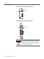
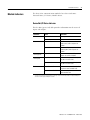
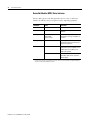
DeviceNet
Communications
For PanelView Plus and
PanelPlus CE Terminals
2711P
User Manual
Important User Information
Solid state equipment has operational characteristics differing from those of
electromechanical equipment. Safety Guidelines for the Application,
Installation and Maintenance of Solid State Controls (publication SGI-1.1
available from your local Rockwell Automation sales office or online at
http://literature.rockwellautomation.com) describes some important
differences between solid state equipment and hard-wired electromechanical
devices. Because of this difference, and also because of the wide variety of
uses for solid state equipment, all persons responsible for applying this
equipment must satisfy themselves that each intended application of this
equipment is acceptable.
In no event will Rockwell Automation, Inc. be responsible or liable for
indirect or consequential damages resulting from the use or application of
this equipment.
The examples and diagrams in this manual are included solely for illustrative
purposes. Because of the many variables and requirements associated with
any particular installation, Rockwell Automation, Inc. cannot assume
responsibility or liability for actual use based on the examples and diagrams.
No patent liability is assumed by Rockwell Automation, Inc. with respect to
use of information, circuits, equipment, or software described in this manual.
Reproduction of the contents of this manual, in whole or in part, without
written permission of Rockwell Automation, Inc., is prohibited.
Throughout this manual, when necessary, we use notes to make you aware
of safety considerations.
WARNING
IMPORTANT
ATTENTION
Identifies information about practices or circumstances that can cause
an explosion in a hazardous environment, which may lead to personal
injury or death, property damage, or economic loss.
Identifies information that is critical for successful application and
understanding of the product.
Identifies information about practices or circumstances that can lead
to personal injury or death, property damage, or economic loss.
Attentions help you identify a hazard, avoid a hazard, and recognize
the consequence
SHOCK HAZARD
Labels may be on or inside the equipment, for example, a drive or
motor, to alert people that dangerous voltage may be present.
BURN HAZARD
Labels may be on or inside the equipment, for example, a drive or
motor, to alert people that surfaces may reach dangerous
temperatures.
Table of Contents
Preface
About This Publication . . . . . . . . . . . .
Topics Covered. . . . . . . . . . . . . . . . . .
Hardware and Software Requirements .
Additional Resources. . . . . . . . . . . . . .
.
.
.
.
.
.
.
.
.
.
.
.
.
.
.
.
.
.
.
.
.
.
.
.
.
.
.
.
.
.
.
.
.
.
.
.
.
.
.
.
.
.
.
.
.
.
.
.
.
.
.
.
.
.
.
.
.
.
.
.
.
.
.
.
.
.
.
.
5
5
5
7
.
.
.
.
.
.
.
.
.
.
.
.
.
.
.
.
.
.
.
.
.
.
.
.
.
.
.
.
.
.
.
.
.
.
.
.
.
.
.
.
.
.
.
.
.
.
.
.
.
.
.
.
.
.
.
.
.
.
.
.
.
.
.
.
.
.
.
.
.
.
.
.
.
.
.
.
.
.
.
.
. 9
. 9
. 9
. 9
11
Chapter 1
DeviceNet Overview
Chapter Objectives . . .
DeviceNet Protocol . . .
Supported Controllers .
DeviceNet Module . . .
Module Indicators . . . .
.
.
.
.
.
.
.
.
.
.
.
.
.
.
.
.
.
.
.
.
.
.
.
.
.
.
.
.
.
.
.
.
.
.
.
.
.
.
.
.
.
.
.
.
.
.
.
.
.
.
.
.
.
.
.
.
.
.
.
.
Chapter 2
Configure the Terminal as a Slave Chapter Objectives . . . . . . . . . . . . . . . . . . . . . . . . . . . . . . . 15
Sample Network Configuration . . . . . . . . . . . . . . . . . . . . . . 15
Device
Configure Communications . . . . . . . . . . . . . . . . . . . . . . . . . 16
Configure RSNetWorx for DeviceNet Software . . . . . . . . . . . 31
Use RSLogix 5000 Software . . . . . . . . . . . . . . . . . . . . . . . . . 44
Chapter 3
Configure the Terminal as a
Scanner
Chapter Objectives . . . . . . . . . . . . .
Configure Communications . . . . . . .
Configure RSNetWorx for DeviceNet
Use RSLogix 5000 Software . . . . . . .
.
.
.
.
.
.
.
.
.
.
.
.
.
.
.
.
.
.
.
.
.
.
.
.
.
.
.
.
.
.
.
.
.
.
.
.
.
.
.
.
.
.
.
.
.
.
.
.
.
.
.
.
.
.
.
.
.
.
.
.
.
.
.
.
.
.
.
.
.
.
.
.
49
49
60
69
Appendix A
Restore Configuration to Local Tab Copy Configuration to Local Tab . . . . . . . . . . . . . . . . . . . . . 71
Index
3
Publication 2711P-UM004B-EN-P - March 2007
4
Table of Contents
Publication 2711P-UM004B-EN-P - March 2007
Preface
About This Publication
PanelView Plus and PanelView Plus CE terminals with a DeviceNet
communications module support DeviceNet scheduled I/O
communications. This guide will show you how to configure
DeviceNet communications between a PanelView Plus terminal and a
ControlLogix controller.
The PanelView Plus and PanelView Plus CE terminals can operate as a
slave or a scanner on the DeviceNet network. You will learn how to
configure a PanelView Plus terminal as a slave and a scanner using
RSView Studio Machine Edition, RSNetWorx for DeviceNet software,
and RSLogix 5000 programming software.
Topics Covered
Chapter 1 Overview of DeviceNet module
Provides an overview of the DeviceNet communication module for
PanelView Plus and PanelView Plus CE devices including supported
controllers and DeviceNet I/O messaging.
Chapter 2 Configure Terminal as a Slave Device
Shows how to configure your PanelView Plus terminal to operate as a
slave device on a DeviceNet network using I/O messaging. The
procedures in this chapter build on the configurations defined in
Chapter 1.
Chapter 3 Configure Terminal as a Scanner
Shows how to configure your PanelView Plus terminal to operate as a
scanner on a DeviceNet network using I/O messaging.
Appendix A Restore Configuration to Local Tab
Shows how to copy the Target tab configuration to the Local tab.
Hardware and Software
Requirements
5
To configure applications for DeviceNet communications, you must
install the appropriate communication module on your PanelView
Plus or PanelView Plus CE terminal. You must also verify that the
correct software and firmware is installed on the development
computer.
Hardware and Software
PanelView Plus 700 to1500
PanelView Plus CE 700 to
1500
PanelView Plus
400/600
RSView Studio
Version 4.0 or later
Version 4.0 or later
RSView Machine Edition
Runtime
Version 4.0 or later
Version 4.0 or later
Publication 2711P-UM004B-EN-P - March 2007
6
Publication 2711P-UM004B-EN-P - March 2007
Hardware and Software
PanelView Plus 700 to1500
PanelView Plus CE 700 to
1500
PanelView Plus
400/600
RSNetWorx for DeviceNet
Version 6.0 or later
V6.0 or later
RSLogix 5000
15.0 or later
15.0 or later
Terminal Communication
Module and Firmware
2711P-RN10H
firmware version 3.16 or later
2711P-RN10C
firmware version 3.16
or later
7
Additional Resources
For more information on RSView Enterprise or RSView Studio
programming software, refer to the online help.
You can download electronic versions of these publications from the
Rockwell Automation website:
http://www.literature.rockwellautomation.com
Publication
Publication Number
PanelView Plus User Manual
2711P-UM001
RSView Machine Edition User Manual
ViewME-UM003
DeviceNet Selection Guide
DNET-SG001
DeviceNet Media Design Installation Guide
DNET-UM072
DeviceNet Tips & Tricks
DNET-BR003
Communication Module Installation Instructions
2711P-IN003
Publication 2711P-UM004B-EN-P - March 2007
8
Publication 2711P-UM004B-EN-P - March 2007
Chapter
1
DeviceNet Overview
Chapter Objectives
This chapter provides an overview of:
•
•
•
•
DeviceNet protocol
Controller support
DeviceNet modules
DeviceNet module indicators
DeviceNet Protocol
The PanelView Plus or PanelView Plus CE terminals support
DeviceNet I/O only. DeviceNet allows direct connection of devices. It
also provides a control architecture that supports multiple processors.
DeviceNet is a trunk/drop or bus-based network that supports up to
64 nodes and operates at 125, 250, or 500 Kbps.
Supported Controllers
A PanelView Plus or PanelView Plus CE terminal with a DeviceNet
communication module can connect with other devices. Typical
controllers supported include:
• 1756-DNB module for the Control Logix network
• 1771-SDN module for the PLC-5 network
• 1747-SDN module for the SLC 5/03 to SLC 5/05 network
DeviceNet Module
There are two DeviceNet communication modules:
• 2711P-RN10C for PanelView Plus 400 and 600 terminals
• 2711P-RN10H for PanelView Plus and PanelView Plus CE 700
to 1500 terminals
For details how to install the modules on the terminals, refer to the
2711P-IN003 installation instructions that ship with the module.
ATTENTION
9
The DeviceNet network is not supported on a personal
computer running RSView Machine Edition software.
Publication 2711P-UM004B-EN-P - March 2007
10
DeviceNet Overview
2711P-RN10C DeviceNet Module for 400 and 600 Terminals
I/O Status Indicator
NET Status
Indicator
MOD Status Indicator
Red
White
Shield
Blue
Black
2711P-RN10H DeviceNet Module for 700 to 1500 Terminals
NET Status
Indicator
MOD Status Indicator
I/O Status Indicator
Red
White
Shield
Blue
Black
WARNING
Publication 2711P-UM004B-EN-P - March 2007
Do not connect or disconnect any communication cable with
power applied to this device or any device on the network. An
electrical arc could cause an explosion in hazardous location
installations. Be sure that power is removed or the area is
nonhazardous before proceeding.
DeviceNet Overview
Module Indicators
11
The DeviceNet communication modules have three indicators:
Network Status, I/O Status, Module Status.
DeviceNet I/O Status Indicator
This bi-color (green/red) LED provides information on the states of
inputs and outputs.
Condition
Status
Indication
Off
Outputs active
All outputs are active.
Inputs active
All inputs are active.
Outputs active
One or more outputs are active and
under control, and no outputs are
faulted.
Inputs active
One or more inputs are active and
producing data, and no inputs are
faulted.
Flashing green(1)
Outputs idle
One or more outputs are idle, and no
outputs are active or faulted.
Flashing red (1)
Outputs faulted
One or more outputs are faulted, and
may be in the fault state.
Inputs faulted
One or more inputs are faulted, and
may be in the fault state.
Outputs forced off
One or more outputs are forced off
(may be an unrecoverable fault).
Input unrecoverable fault
One or more inputs has an
unrecoverable fault.
Green
Red
(1)
The flash rate of the LED is approximately 1 flash per second. The LED should be on for approximately 0.5
seconds and off for approximately 0.5 seconds.
Publication 2711P-UM004B-EN-P - March 2007
12
DeviceNet Overview
DeviceNet Module (MOD) Status Indicator
This bi-color (green/red) LED provides device status. It indicates
whether or not the device has power and is operating properly.
Condition
Status
Indication
Off
No power
No power applied to device.
Green
Device operational
Device is operating in a normal
condition.
Flashing green(1)
Device in standby
(device needs
commissioning)
Device needs commissioning due to
configuration missing, incomplete, or
incorrect.
Flashing red (1)
Recoverable fault
For example, the device’s scan list
configuration does match the actual
network configuration.
Red
Unrecoverable fault
Device has an unrecoverable fault.
Cycle power to your computer. If the
problem persists, the device may
need to be replaced.
Device self testing
Device is in self test. Refer to the
DeviceNet Specification, Volume II,
Identity Object.
(1)
Publication 2711P-UM004B-EN-P - March 2007
The flash rate of the LED is approximately 1 flash per second. The LED should be on for approximately 0.5
seconds and off for approximately 0.5 seconds.
DeviceNet Overview
13
DeviceNet Network (NET) Status Indicator
This bi-color (green/red) LED indicates the status of the
communication link.
Condition
Status
Indication
Off
Not powered
Device is not online.
Not online
The device has not completed the
Dup_MAC_ID test yet.
The device may not be powered; look
at the Module Status LED.
Online
Device is online, but has no
connections in the established state.
Not connected
The device has passed the
Dup_MAC_ID test, is online, but has
no established connections to other
nodes.
Green
Link okay, online, connected
The device is online and has
connections in the established state.
Flashing red (1)
Connection timeout
One or more I/O connections are in
the timed-out state.
Red
Critical link failure
Failed communication device. The
device has detected an error that has
rendered it incapable of
communicating on the network
(Duplicate MAC ID or Bus-off).
Flashing green(1)
Check network integrity and
communication rate of all devices.
Then cycle power to the card by
shutting down and cycling power to
your computer.
(1)
The flash rate of the LED is approximately 1 flash per second. The LED should be on for approximately 0.5
seconds and off for approximately 0.5 seconds.
ATTENTION
Extensive use of change-of-state connections, particularly with
rapidly changing data, can adversely impact the available
DeviceNet network bandwidth. If the network bandwith
becomes consumed, some devices may only be able to
communicate intermittently. This can result in timeout errors
and possible loss of data. If timeouts occur, consider changing
the connection type for some of the change-of-state
connections to cyclic or polled.
Publication 2711P-UM004B-EN-P - March 2007
14
DeviceNet Overview
Publication 2711P-UM004B-EN-P - March 2007
Chapter
2
Configure the Terminal as a Slave Device
Chapter Objectives
The procedures in this chapter will show you how to configure a
PanelView Plus terminal to operate as a slave device on a DeviceNet
network. A ControlLogix processor with a 1756-DNB DeviceNet
module will scan inputs and outputs from the PanelView Plus
terminals.
You will learn how to:
• configure communications for the PanelView Plus terminal and
1756-DNB module using RSLinx Enterprise software in RSView
Studio software.
• create a DeviceNet configuration using RSNetWorx for
DeviceNet software.
• add the DeviceNet module I/O configuration to the ControlLogix
tag database using RSLogix 5000 software.
Sample Network
Configuration
The example configures DeviceNet I/O messaging for a numeric input
and numeric output from a PanelView Plus terminal to a 1756-L63
ControlLogix processor, version 15.0.
• The PanelView Plus terminal has a network node address of 2.
• 1756-L63 ControlLogix processor, version 15.0, in slot 0
communicates via the 1756-DNB DeviceNet scanner module at
network node address 1 in slot 2.
1756-DNB Scanner
Node 1
Ethernet
Network
L
6
3
RSLogix 5000 network
RSNetWorx network
RSView Studio network
E
N
B
T
D
N
B
DeviceNet
Cable
Node 2
PanelView Plus with
DeviceNet module
15
Publication 2711P-UM004B-EN-P - March 2007
16
Configure the Terminal as a Slave Device
Configure Communications
After creating your Machine Edition application, you are ready to
configure communications using RSLinx Enterprise software.
1. Open RSView Studio software.
2. In the Application Explorer dialog, double-click RSLinx
Enterprise software to expand the tree.
3. Double-click Communication Setup.
4. If prompted, select Create a New Configuration and click Finish.
5. On the Local tab, right-click the 1789-A17 Backplane icon and
select Add Device.
This is the virtual backplane of the PanelView Plus or PanelView
Plus CE device.
Publication 2711P-UM004B-EN-P - March 2007
Configure the Terminal as a Slave Device
17
6. In the Add Device Selection dialog, select the communications
card appropriate for your terminal size and click OK.
• The correct card for the PanelView Plus 400 and 600 terminals
is 2711P-RN10C.
• The correct card for the PanelView Plus 700-1500 terminals is
2711P-RN10H.
7. Set the node address to 2, the communication rate to match the
1756-DNB DeviceNet module, and click OK.
The General tab of the DeviceNet Scanner Properties dialog
specifies the name, node address, virtual backplane slot, and
communication rate of the DeviceNet scanner. The virtual
backplane of the PanelView Plus has two slots. Because the
terminal resides in slot 0, the DeviceNet scanner is automatically
assigned to slot 1.
Publication 2711P-UM004B-EN-P - March 2007
18
Configure the Terminal as a Slave Device
Configure the Slave Inputs and Outputs
You are now ready to configure the slave inputs and outputs in the
PanelView Plus terminal. For the example used in this chapter, the
1756-DNB DeviceNet module will scan these inputs and outputs.
• One DINT or 4 bytes of input data
• One DINT or 4 bytes of output data
IMPORTANT
Typically these address blocks will be larger. Minimize the
number of address blocks going to a single device.
What differentiates the PanelView Plus terminal as a slave or a scanner
is the node you specify for each block of data. The device you
configure data for via the I/O Configuration tab is the slave on the
network. If the device node matches the node address for the
PanelView Plus terminal, then it will operate as a slave. In this
example, the node address is 2.
Definition of Inputs and Outputs
Inputs and outputs are in reference to the PanelView Plus DeviceNet
module and correspond to RSNetWorx terminology. In other words,
the output of a controller is an input to the PanelView Plus terminal.
RSView ME software can read inputs and outputs, but only write to
outputs configured in the PanelView Plus terminal.
Configure the Slave Input Data
1. On the I/O Configuration tab, right-click the Input icon and
select Add Address Block.
Publication 2711P-UM004B-EN-P - March 2007
Configure the Terminal as a Slave Device
19
2. In the Address Block Properties dialog, set the Start Byte to 0,
Length in Bytes to 4, and click OK.
The address block 0-3 Bytes is added under Inputs.
3. Right-click on the new address block 0-3 Bytes and select Add
Device to define the PanelView Plus terminal as the slave for the
input address block.
4. In the Device Properties dialog of the input address block, select
Node 2 and click OK.
Publication 2711P-UM004B-EN-P - March 2007
20
Configure the Terminal as a Slave Device
Because the device node is the same node as the PanelView
Plus terminal, Node 2 will operate as a slave for the input data.
The 1756-DNB scanner will scan this data.
A dimmed icon appears under the Input address block for
Device 02. This indicates the PanelView Plus terminal is the
slave.
Publication 2711P-UM004B-EN-P - March 2007
Configure the Terminal as a Slave Device
21
Create an Input Alias
To make connections to objects, aliases are required. You must create
an alias for the input address block. The aliases serve as the
connection reference you select in RSView Studio software.
1. Right-click the 0-3 Bytes icon and select Add Alias.
2. In the Alias Properties dialog, select these properties and click
OK to add the alias to the input address block:
• Alias Data Type = DINT
• Alias Name = Slave_Input
• Start Byte = 0
• Array Count = 1
Publication 2711P-UM004B-EN-P - March 2007
22
Configure the Terminal as a Slave Device
The Array Count lets you quickly configure multiple aliases with
the same prefix.
Swapping of bytes or words is necessary for some controllers
such as SLC controller. Refer to Help for more information.
The slave input is now configured with:
• Address length of 4 bytes, starting at byte 0
• Slave device at node 2, which is the PanelView Plus terminal
• Alias of Slave_Input for the input address block
Publication 2711P-UM004B-EN-P - March 2007
Configure the Terminal as a Slave Device
23
Configure the Slave Output Data
Follow the same procedure to add a slave output block to the I/O
configuration. The 1756-DNB DeviceNet scanner will scan this output.
1. On the I/O Configuration tab, right-click the Output icon and
select Add Address Block.
2. In the Address Block Properties dialog, set the Start Byte to 0,
Length in Bytes to 4, and click OK.
The address block 0-3 Bytes is added under Outputs.
Publication 2711P-UM004B-EN-P - March 2007
24
Configure the Terminal as a Slave Device
3. Right-click the new address block 0-3 Bytes and select Add
Device to define the PanelView Plus terminal as the slave for the
output address block.
4. In the Device Properties dialog for the output address block,
select Node 2 and click OK.
Similar to the input data, the PanelView Plus terminal will
operate as a slave for the output data. The 1756-DNB scanner
will scan this output data.
A dimmed icon appears under the Output address block for
Device 02 . This indicates the PanelView Plus terminal is the
slave.
Publication 2711P-UM004B-EN-P - March 2007
Configure the Terminal as a Slave Device
25
Create an Output Alias
To make connections to objects, aliases are required. Similar to the
input alias, you must create an alias for the output block.
1. Right-click the 0-3 Bytes icon under Output and select Add Alias.
2. In the Alias Properties dialog, select these properties and then
click OK to add the alias to the output address block:
• Alias Data Type = DINT
• Alias Name = Slave_Output
• Start Byte = 0
• Array Count = 1
• Initial Value = 0
If you do not enter an initial value, a warning message
indicates that default values will be used.
Publication 2711P-UM004B-EN-P - March 2007
26
Configure the Terminal as a Slave Device
The slave output is now configured with the following information:
• Address length of 4 bytes, starting at byte 0.
• Slave device on node 2, which is the PanelView Plus terminal.
• Alias of Slave_Output for the output address block.
3. Click OK to save the configuration.
Create a Shortcut
The Local tab in the Communciation Setup allows the aliases you
created to be browsed from within RSView Studio software. It also lets
you to test run the application on a PC with a 1784-PCIDS DeviceNet
PCI Communication Interface card.
ATTENTION
DeviceNet network is not supported on a PC running
RSView Machine Edition software.
Create a shortcut for the PanelView Plus communication setup and
apply it the DeviceNet driver that was added to the backplane.
1. From the Communication Setup dialog click Add.
2. For this example, enter DNET as the name of the shortcut.
Publication 2711P-UM004B-EN-P - March 2007
Configure the Terminal as a Slave Device
27
3. With the new shortcut selected and while on the Local tab,
select the 2711P-RN10H DeviceNet Scanner.
4. Click Apply.
The shortcut has been applied to the DeviceNet driver.
Publication 2711P-UM004B-EN-P - March 2007
28
Configure the Terminal as a Slave Device
Browse for Tags
While you are creating an RSView Machine Edition application, you
will be creating objects and assigning tags in the Connection tab.
The structure of the DeviceNet Input Table looks like this when
browsing for tags.
Publication 2711P-UM004B-EN-P - March 2007
Configure the Terminal as a Slave Device
29
The structure of the DeviceNet Output Table looks like this when
browsing for tags.
Copy RSLinx Configuration to the Target Tab
When the application is complete, you must copy the RSLinx
configuration from the Local tab to the Target tab before you compile
the .mer file.
The Target tab contains the configuration the PanelView Plus terminal
uses to run the application. For I/O network configurations such as
DeviceNet, the shortcut configurations should be the same. For other
protocols, it is not necessary to have identical configurations.
Publication 2711P-UM004B-EN-P - March 2007
30
Configure the Terminal as a Slave Device
1. Click Copy in Communication Setup.
The following dialog opens.
2. Click Yes.
The Communications Setup dialog will appear.
3. Click OK from the Communications Setup dialog to save the
configuration and close the dialog.
Create a runtime .mer file and download it to the PanelView
Plus terminal. Load the application in the terminal but do not
run the application. You must map the data between the
PanelView Plus terminal and the 1756-DNB scanner using
RSNetWorx for DeviceNet software.
Publication 2711P-UM004B-EN-P - March 2007
Configure the Terminal as a Slave Device
Configure RSNetWorx for
DeviceNet Software
31
This section shows how to create a DeviceNet configuration using
RSNetWorx for DeviceNet software. You must now map the
PanelView Plus I/O configuration to the 1756-DNB DeviceNet
module.
1. Open RSNetWorx for DeviceNet software by selecting Start >
Menu > Programs > Rockwell Software > RSNetWorx >
RSNetworx for DeviceNet.
2. Create a new DeviceNet configuration and click OK.
The example configuration uses online browsing for devices on
the DeviceNet network.
3. Make sure all connections are made and that the communication
rates match on all devices.
4. On the PanelView Plus, load the runtime .mer application in
RSView Machine Edition, but do not run it as this time.
IMPORTANT
Do not run the application until the scanlist is
downloaded to the terminal. A scanlist will not
download to the terminal if the application is running.
5. When the network and devices are ready, go online by clicking
the icon on the toolbar.
Publication 2711P-UM004B-EN-P - March 2007
32
Configure the Terminal as a Slave Device
The Browse for Network dialog opens.
6. Select the path of the DeviceNet network and click OK.
Publication 2711P-UM004B-EN-P - March 2007
Configure the Terminal as a Slave Device
33
When the network is scanned, the devices display in the
network dialog. The dialog shows an icon for both the
1756-DNB module and the PanelView Plus/PanelView Plus CE
DeviceNet.
PV Plus/PV Plus CE
DeviceNet
Configure Slave I/O for the PanelView Plus Terminal
You must configure the slave I/O before adding it to the 1756-DNB
scanlist. This section shows how to configure slave I/O for the
PanelView Plus terminal.
Publication 2711P-UM004B-EN-P - March 2007
34
Configure the Terminal as a Slave Device
1. Double-click the PanelView Plus/PanelView Plus CE DeviceNet
icon to view the general properties.
2. Select the Module tab.
Because you are editing the configuration online, you are
prompted to:
• upload the current configuration in the module.
• download the configuration from the software.
Publication 2711P-UM004B-EN-P - March 2007
Configure the Terminal as a Slave Device
35
3. Click the Upload button to edit the configuration.
When the upload is complete the Module tab appears.
4. Click Slave Mode.
The Slave Mode configuration dialog appears.
5. Check the Enable Slave Mode checkbox to enable Slave mode
and edit the Slave mode configuration.
Publication 2711P-UM004B-EN-P - March 2007
36
Configure the Terminal as a Slave Device
6. Under Change of State / Cyclic, set these parameters to use
Cyclic I/O messaging:
• Select Cyclic
• Input Size = 4
• Output Size = 4
The configuration will transfer 4 bytes of input data and 4 bytes
of output data using cyclic I/O messaging.
TIP
The input size should match the size of the input address block
in RSView Machine Edition software. Similarly, the output size
of the output address block in RSView Machine Edition should
also match.
7. Click OK to save the data.
Map the I/O to the PanelView Plus Image Table
You must map the I/O data to the PanelView Plus image table so that
it can be scanned by the 1756-DNB DeviceNet module.
1. Select the Input tab to map the input data to the image table.
Publication 2711P-UM004B-EN-P - March 2007
Configure the Terminal as a Slave Device
37
The input data you just configured appears in the top window.
2. Click AutoMap to map the data to the least significant word in
the PanelView Plus input image table.
Publication 2711P-UM004B-EN-P - March 2007
38
Configure the Terminal as a Slave Device
3. Select the Output tab to view the output table.
4. Click AutoMap to map the output data to the least significant
word in the PanelView Plus output image table.
5. Click OK to save the configuration.
Publication 2711P-UM004B-EN-P - March 2007
Configure the Terminal as a Slave Device
39
You are prompted to download the I/O configuration to the
PanelView Plus terminal.
6. Click Yes to download the I/O configuration.
Publication 2711P-UM004B-EN-P - March 2007
40
Configure the Terminal as a Slave Device
Map the PanelView Plus I/O to the 1756-DNB Scanlist
You can now add the PanelView Plus I/O data to the scanlist of the
1756-DNB DeviceNet module.
1. In the network dialog, double-click the 1756-DNB icon to access
the 1756-DNB properties.
2. Select the Module tab.
Because you are editing the configuration online, you are
prompted to:
• upload the current configuration in the module.
• download the configuration from the software.
3. Click Upload to edit the current configuration.
Publication 2711P-UM004B-EN-P - March 2007
Configure the Terminal as a Slave Device
41
When the upload is complete, the module tab will open.
4. From the Module tab, select Slot 2 which is the location of the
1756-DNB module in the ControlLogix rack.
5. Select the Scanlist tab to view and edit the 1756-DNB scanlist.
The PanelView Plus terminal appears as an available device.
This means you can add it to the scanlist.
Publication 2711P-UM004B-EN-P - March 2007
42
Configure the Terminal as a Slave Device
6. Select the PanelView Plus device and click > to add the device
to the scanlist.
The Automap on Add checkbox is selected. When you add the
device to the scanlist, the slave inputs and outputs are
automatically added to the input and output tables.
TIP
If the Automap on Add checkbox was not checked, you
would need to manually map the data on the Input tab.
7. Select the Input tab to verify that the PanelView Plus I/O is
mapped to the Input Assembly Data file.
The DINT slave output (Slave_Output) created for the
PanelView Plus terminal in RSLinx Enterprise software resides in
the first 4 bytes of the 1756-DNB input table.
Publication 2711P-UM004B-EN-P - March 2007
Configure the Terminal as a Slave Device
43
8. Select the Output tab to verify that the PanelView Plus I/O is
mapped to the 1756-DNB output image file.
The DINT slave input (Slave_Input alias) created for the
PanelView Plus slave in RSLinx Enterprise software resides in the
first 4 bytes of the 1756-DNB output table.
9. Click OK.
You are prompted to download the changes to the 1756-DNB
module.
10. Click Yes to download the configuration.
The 1756-DNB module is now configured to scan the slave I/O
in the PanelView Plus terminal.
Publication 2711P-UM004B-EN-P - March 2007
44
Configure the Terminal as a Slave Device
Summary
The scanlists are now configured for both the 1756-DNB DeviceNet
module and the PanelView Plus terminal.
IMPORTANT
Use RSLogix 5000 Software
To change the scanlist for a device on the network, you must
place the device in Idle mode before downloading the changes.
On the PanelView Plus terminal, you can load the application
but not run it.
You must now add the DeviceNet I/O configuration in the 1756-DNB
module to the controller tags database in RSLogix 5000 software. You
can then put the 1756-DNB module in Run mode and initiate data
transfer.
For these examples, the module is in slot 0.
1. Verify that the 1756-L63 ControlLogix processor is in slot 0.
2. Open a new application.
3. Right-click the I/O Configuration icon and select New Module.
Publication 2711P-UM004B-EN-P - March 2007
Configure the Terminal as a Slave Device
45
The By Category tab displays a list of module types.
4. Expand Communications and select 1756-DNB.
Publication 2711P-UM004B-EN-P - March 2007
46
Configure the Terminal as a Slave Device
After selecting the module, you are prompted to select the Major
Revision of the 1756-DNB module.
5. Select the Major Revision of the module installed in the
ControlLogix rack and select OK.
Publication 2711P-UM004B-EN-P - March 2007
Configure the Terminal as a Slave Device
47
6. In the New Module dialog, enter these parameters:
• name for the module.
• slot location of the 1756-DNB module in the ControlLogix rack,
in this case, slot 2.
7. Click OK.
You have just added the 1756-DNB module I/O configuration to
the ControlLogix controller tag database.
Publication 2711P-UM004B-EN-P - March 2007
48
Configure the Terminal as a Slave Device
8. To view the tags, double-click the Controller Tags icon in the
tree.
Notice that the input, output, and status tags are specific to the
slot the 1756-DNB module resides in, which is slot 2. The inputs
and outputs mapped in RSNetWorx software now reside in:
• Local:2:I.Data array for inputs.
• Local:2:O:Data array for outputs.
9. To enable DeviceNet communications, put the DeviceNet
1756-DNB module in Run mode by setting the run mode bit in
the output command register.
Local:2:O.Command.Register.Run.
You can do this in the ladder logic or by accessing the tag
directly.
10. Download the program to the ControlLogix processor and put
the program in run mode.
Publication 2711P-UM004B-EN-P - March 2007
Chapter
3
Configure the Terminal as a Scanner
Chapter Objectives
The procedures in this chapter build on the example configuration in
Chapter 2. In this chapter, you will configure the PanelView Plus as a
scanner and the 1756-DNB DeviceNet module as the slave device. The
PanelView Plus will scan I/O from the 1756-DNB DeviceNet module.
Configure Communications
In this section, you will learn how to:
• configure slave input and output data for the 1756-DNB module.
• view the structure of the DeviceNet input and output table when
browsing for tags.
• copy the RSLinx software configuration to the Target tab.
Configure the Slave Inputs and Outputs
IMPORTANT
To change the scanlist for a device on the network, you must
place the device in Idle mode before downloading the changes.
For the PanelView Plus, you can load the application but not run
it. For the 1756-DNB module, put the ControlLogix processor in
Program mode.
To place the device in Idle mode:
• For the PanelView Plus, load the application but do not run it.
• For the 1756-DNB module, put the ControlLogix 1756-L63
processor in Program mode. This action will clear the run bit
Local:2:O.CommandRegister.Run.
You are now ready to configure the slave inputs and outputs in the
1756-DNB module. The PanelView Plus terminal will scan these
inputs and outputs.
• One DINT or four bytes of input data, starting at byte 4.
• One DINT or four bytes of output data, starting at byte 4.
The PanelView Plus can scan 2048 bytes of input data and 2048 bytes
of output data. The number of input and output bytes is minus any
slave I/O data configured in the PanelView Plus.
49
Publication 2711P-UM004B-EN-P - March 2007
50
Configure the Terminal as a Scanner
For each block of data, you will enter the node address of the
1756-DNB DeviceNet module to indicate that the module is the slave
device. The node address of the 1756-DNB module for the sample
configuration is node 1.
Configure the Scanner Input Data
You are now ready to configure the scanner input data. You will do
this in Communications Setup in RSView Machine Edition under
RSLinx Enterprise software.
The example used in this chapter builds from the Slave configuration
example. You can configure a PanelView Plus terminal as both a
scanner and slave for the same application.
1. On the I/O Configuration Tab, right-click the Input icon and
select Add Address Block.
2. In the Address Block Properties dialog set the Start Byte to 4,
Length in Bytes to 4, and click OK.
The address block 4-7 Bytes is added under Inputs.
Publication 2711P-UM004B-EN-P - March 2007
Configure the Terminal as a Scanner
51
3. Right-click the new 4-7 address block Bytes and select Add
Device to define the 1756-DNB DeviceNet module as the slave
device for the input address block.
4. In the Device Properties dialog for the input address block,
select the node of the slave device, in this example Node 1, and
click OK.
Node 1 indicates that the 1746-DNB module will operate as the
slave for the input data. The PanelView Plus will scan this data
from the module.
Create an Input Alias
To make connections to objects, aliases are required. You must create
an alias for the input address block.
Publication 2711P-UM004B-EN-P - March 2007
52
Configure the Terminal as a Scanner
1. Right-click the 4-7 Bytes icon and select Add Alias.
Publication 2711P-UM004B-EN-P - March 2007
Configure the Terminal as a Scanner
53
2. In the Alias Properties dialog, select these properties and then
click OK to add the alias to the input address block:
• Alias Data Type = DINT
• Alias Name = Scanner_Input
• Start Byte = 4
• Array Count = 1
The slave input is now configured with:
• Address block of four bytes, starting at byte 4
• Slave device on node 1, which is the 1756-DNB module
• Alias of Scanner_Input for the input address block
Publication 2711P-UM004B-EN-P - March 2007
54
Configure the Terminal as a Scanner
Configure the Scanner Output Data
You are now ready to configure the scanner output data. You will do
this in Communications Setup in RSView Machine Edition under
RSLinx Enterprise software.
You can configure a PanelView Plus terminal as both a scanner and
slave for the same application. Add a scanner output block to the I/O
configuration. The PanelView Plus terminal will scan this output
block.
1. Right-click the Output icon to add an Address Block.
2. In the Address Block Properties dialog, set the Start Byte to 4,
Length in Bytes to 4, and click OK.
The address block 4-7 Bytes is added under Outputs.
Publication 2711P-UM004B-EN-P - March 2007
Configure the Terminal as a Scanner
55
3. Right-click the new address block 4-7 Bytes and select Add
Device to define the 1756-DNB module as the slave device for
the output block.
4. In the Device Properties dialog for the output address block,
select Node 1 and click OK.
Similar to the input data, the 1756-DNB module will operate as a
slave for the output data. The PanelView Plus will scan this
output data from the module.
Publication 2711P-UM004B-EN-P - March 2007
56
Configure the Terminal as a Scanner
Create an Output Alias
Similar to the input alias, you need to create an alias for the output
block.
1. Right-click the 4-7 Bytes icon under Output and select Add Alias.
2. In the Alias Properties dialog, select these properties and then
click OK to add the alias to the address block:
• Alias Data Type = DINT
• Alias Name = Scanner_Output
• Start Byte = 4
• Array Count = 1
• Initial Value = 0
If you do not enter an initial value, a warning message indicates
that default values will be used.
Publication 2711P-UM004B-EN-P - March 2007
Configure the Terminal as a Scanner
57
The scanner output is now configured with:
• Address block of four bytes, starting at byte 4
• Slave device on node 1, which is the 1756-DNB module
• Alias of Scanner_Output for the output address block
3. Click OK to save the configuration.
4. To exit Communications Setup, click OK to save the
configuration and close the dialog.
Publication 2711P-UM004B-EN-P - March 2007
58
Configure the Terminal as a Scanner
Browse for Tags
The structure of the DeviceNet Input Table looks like this when
browsing for tags.
Both slave and scanned alias are listed together. It is important to
create an alias that will be meaningful to you when you are
developing your RSView Machine Edition application.
Publication 2711P-UM004B-EN-P - March 2007
Configure the Terminal as a Scanner
59
The structure of the DeviceNet Output Table looks like this when
browsing for tags.
Copy RSLinx Enterprise Configuration to the Target Tab
When all the object connections are made and the application is
complete, click Copy in Communication Setup to copy the RSLinx
Enterprise configuration from the Local tab to the Target tab.
Create a runtime .mer file and download to the PanelView Plus
terminal. Load the application in the terminal but do not run the
application. You must first map the data between the PanelView Plus
and the 1756-DNB scanner using RSNetWorx for DeviceNet software.
Publication 2711P-UM004B-EN-P - March 2007
60
Configure the Terminal as a Scanner
Configure RSNetWorx for
DeviceNet
In this section, you will use RSNetWorx for DeviceNet to configure
slave I/O for the 1756-DNB DeviceNet module and map the I/O to the
PanelView Plus terminal.
Before downloading the scanlists to the PanelView Plus and
1756-DNB module, the devices must be in Idle mode.
• For the PanelView Plus, load the application but do not run it.
• For the 1756-DNB module, put the ControlLogix 1756-L63
processor in Program mode. This action will clear the run bit
Local:2:O.CommandRegister.Run.
Configure Slave I/O for the 1756-DNB Module
To configure the slave inputs and outputs in the 1756-DNB module
you must be online.
1. In the RSNetWorx for DeviceNet dialog, double-click the
1756-DNB icon to open the 1756-DNB properties dialog.
Publication 2711P-UM004B-EN-P - March 2007
Configure the Terminal as a Scanner
61
The 1756-DNB properties dialog opens.
2. Select the Module tab and verify that the slot number is 2.
Slot 2 is the location of the 1756-DNB module in the
ControlLogix rack.
Publication 2711P-UM004B-EN-P - March 2007
62
Configure the Terminal as a Scanner
3. Click Slave Mode button.
The Slave Mode configuration dialog appears.
4. Check the Enable Slave Mode checkbox to enable Slave mode
and edit the Slave mode configuration.
5. Under Change of State / Cyclic, set these parameters to use
Cyclic I/O messaging:
• Select Cyclic
• Input Size = 4
• Output Size = 4
The configuration will transfer 4 bytes of input data and 4 bytes
of output data using cyclic I/O messaging.
TIP
The input size should match the size of the input address block
in RSView Machine Edition. Similarly, the output size of the
output address block in RSView Machine Edition should also
match.
6. Click OK to save the data.
Publication 2711P-UM004B-EN-P - March 2007
Configure the Terminal as a Scanner
63
Map the I/O to the 1756-DNB Image Table
You must now map the I/O data to the image table of the 1756-DNB
module so that it can be scanned by the PanelView Plus terminal.
1. Select the Input tab to map the input data to the image table.
The input data just configured appears in the top window.
2. Select node 1, which represents the 1756-DNB slave mode I/O
and click AutoMap to map the data to the next least significant
DWord in the 1756-DNB input image table.
Publication 2711P-UM004B-EN-P - March 2007
64
Configure the Terminal as a Scanner
3. Select the Output tab to view the output table.
4. Select node 1 and click AutoMap to map the output data to the
least significant DWord in the 1756-DNB output image table.
5. Click OK to save the configuration.
You are prompted to download the I/O configuration to the
1756-DNB module.
6. Select Yes to download the configuration.
Publication 2711P-UM004B-EN-P - March 2007
Configure the Terminal as a Scanner
65
Map the 1756-DNB I/O to the PanelView Plus Scanlist
You are now ready to add the I/O configuration in the 1756-DNB
module to the scanlist of the PanelView Plus terminal. The PanelView
Plus can then scan this data.
1. In the Network dialog, double-click the PanelView
Plus/PanelView Plus CE DeviceNet icon.
The PanelView Plus/PanelView Plus CE DeviceNet dialog
opens.
Publication 2711P-UM004B-EN-P - March 2007
66
Configure the Terminal as a Scanner
2. Select the Scanlist tab to view and edit the PanelView Plus
scanlist.
The 1756-DNB module appears as an available device. This
means you can add it to the Scanlist.
3. Select the 1756-DNB device and click > to add the device to the
Scanlist.
The Automap on Add checkbox is checked. When you add the
device to the Scanlist, the slave inputs and outputs are
automatically added to the input and output image tables.
TIP
Publication 2711P-UM004B-EN-P - March 2007
If the Automap on Add checkbox was not checked, you
would need to manually map the data on the Input tab.
Configure the Terminal as a Scanner
67
4. Select the Input tab to verify that the 1756-DNB data is mapped
to the PanelView Plus input image file.
The DINT slave output (Scanner_Output) created in RSLinx
Enterprise software resides in the first 4 bytes of the PanelView
Plus Input table. The Input tab shows the data mapped
correctly.
5. Select the Output tab to verify that the 1756-DNB data is
mapped to the PanelView Plus output image file.
The DINT slave input (Scanner_Input) created in RSLinx
Enterprise software resides in the first 4 bytes of the PanelView
Publication 2711P-UM004B-EN-P - March 2007
68
Configure the Terminal as a Scanner
Plus output table. The Output tab shows the data mapped
correctly.
TIP
If the Automap on Add checkbox was not checked, you
would need to manually map the data on the Output tab.
6. Click OK.
You are prompted to download the changes to the PanelView
Plus terminal.
7. Click Yes to download the configuration.
The PanelView Plus is now configured to scan the slave I/O data
in the 1756-DNB DeviceNet module.
Summary
The scanlists are now configured for both the 1756-DNB DeviceNet
module and the PanelView Plus terminal.
IMPORTANT
To change the scanlist for a device on the network, you must
place the device in Idle mode before downloading the changes.
For the PanelView Plus, you can load the application but not run
it. For the 1756-DNB module, put the ControlLogix processor in
Program mode.
You are now ready to put each device in Run mode.
• For the PanelView Plus, run the Machine Edition .mer
application in the terminal.
• For the 1756-DNB module, enable the run bit in the ladder
program using RSLogix 5000 software.
Publication 2711P-UM004B-EN-P - March 2007
Configure the Terminal as a Scanner
Use RSLogix 5000 Software
69
During the first part of the example configuration in Chapter 2:
• you added the 1756-DNB I/O configuration to the 1756-L63
controller tags database using RSLogix 5000 software.
• you then set the run bit Local:2:O.CommandRegister.Run in the
output command register
You did this to enable communications between the PanelView
Plus and the 1756-DNB DeviceNet module.
In the Configure RSNetWorx for DeviceNet software section of this
chapter, you put the processor in Program mode to clear the
Command Register run bit. Because the 1756-DNB was in Idle mode,
you were able to download the scanlist to the 1756-DNB module. You
can now put 1756-DNB module in Run mode. In the 1756-DNB
command register set the run bit Local:2:O.CommandRegister.Run.
Summary
The PanelView Plus is now ready to operate as a scanner on the
DeviceNet network. The terminal can scan the configured slave I/O
data from the 1756-DNB module.
Publication 2711P-UM004B-EN-P - March 2007
70
Configure the Terminal as a Scanner
Publication 2711P-UM004B-EN-P - March 2007
Appendix
A
Restore Configuration to Local Tab
In some cases, it may be necessary to edit an application after the
DeviceNet configuration on the Local tab has changed or has been
moved to a different computer. The RSLinx Enterprise Local tab
configuration stays resident on the desktop computer, regardless of
which application is being edited.
Copy Configuration to Local
Tab
The following procedure shows how to copy the Target tab
configuration for an application to the Local tab to allow for browsing
for tags.
IMPORTANT
This procedure will overwrite all driver configurations on the
Local tab with all of the driver configurations that were on the
Target tab when the application was backed up.
Make sure that the DeviceNet configuration is saved, make sure the
application is backed up using Application Manager.
When you are ready to resume editing, restore the application using
the Application Manager. This will create an XML file with the
restored I/O configuration. For RSView Studio software, you must
complete the following steps.
1. Close RSView Studio software.
2. Disable the RSLinx Enterprise service within the Service Control
Manager (Control Panel>Administrative Tools>Services).
3. Double-click RSLinx Enterprise.
4. Make a backup copy of the current RSLinxNG.xml file in
C:\Documents and Settings\All Users\Application
Data\Rockwell\RSLinx Enterprise.
5. Rename the Restored_restoredAppNAme_RSLinxNG.xml to
RSLinxNG.xml.
6. Re-enable and restart the RSLinx Enterprise software.
71
Publication 2711P-UM004B-EN-P - March 2007
72
Restore Configuration to Local Tab
To allow browsing for tags, open the Communication Setup under the
RSLinx Enterprise tree and apply the shortcut to the DeviceNet driver
on the Local tab. If changes are made to the driver configuration on
the Local tab, be sure to copy this configuration to the Target tab
using the Copy button on the Communication Setup dialog.
Publication 2711P-UM004B-EN-P - March 2007
Index
Numerics
2711P-RN10C 9
2711P-RN10H 9
A
alias
input 21, 51
output 25
N
NET 13
network 15
network configuration 15
network status indicators 11
O
output alias 25
outputs 18
B
browsing for 58
C
communications 16, 49
scanner 49
slave device 16
configuration
copy 71
network 15
PanelView Plus 33
restore 71
RSLinx 29
RSLogix 5000 69
RSNetWorx 31, 60
scanner 49, 50, 54
slave 23
slave device 15
slave inputs 18
slave outputs 18
D
DeviceNet module 9
2711P-RN10C 9
2711P-RN10H 9
I
I/O 36
I/O mapping 36, 40
I/O status indicators 11
image table 36
input alias 21, 51
inputs 18
P
PanelView Plus
1756-DNB 40
configuration 33
I/O mapping 36
1756-DNB 40
image table 36
slave I/O 33
protocol 9
R
RSLinx 29
configuration 29
RSLogix 5000 44, 69
RSNetWorx 31, 60
configuration 31
S
scanlist 40
scanner 54
configuration 54
input data 50
output data 54
shortcut 26
slave device 15
communications 16
configuration 15
slave outputs
configuration 18
status indicators
I/O 11
module (MOD) 12
network (NET) 13
supported controllers 9
M
MOD 12
module status indicators 11
T
tags 28, 58
browsing for 28
Publication 2711P-UM004B-EN-P - March 2007
74
Index
Publication 2711P-UM004B-EN-P - March 2007
Rockwell Automation
Support
Rockwell Automation provides technical information on the web to assist you
in using its products. At http://support.rockwellautomation.com, you can find
technical manuals, a knowledge base of FAQs, technical and application
notes, sample code and links to software service packs, and a MySupport
feature that you can customize to make the best use of these tools.
For an additional level of technical phone support for installation,
configuration and troubleshooting, we offer TechConnect Support programs.
For more information, contact your local distributor or Rockwell Automation
representative, or visit http://support.rockwellautomation.com.
Installation Assistance
If you experience a problem with a hardware module within the first 24
hours of installation, please review the information that's contained in this
manual. You can also contact a special Customer Support number for initial
help in getting your module up and running:
United States
1.440.646.3223
Monday – Friday, 8am – 5pm EST
Outside United
States
Please contact your local Rockwell Automation representative for any
technical support issues.
New Product Satisfaction Return
Rockwell tests all of its products to ensure that they are fully operational
when shipped from the manufacturing facility. However, if your product is
not functioning and needs to be returned:
United States
Contact your distributor. You must provide a Customer Support case
number (see phone number above to obtain one) to your distributor in
order to complete the return process.
Outside United
States
Please contact your local Rockwell Automation representative for
return procedure.
PanelView Plus, VersaView, ControlLogix, TechConnect, RSView Studio, RSView Machine Edition, RSNetWorx
for DeviceNet, RSLogix 5000, RSView, PLC-5, SLC, RSLinx, RSLinx Enterprise, RSNetWorx, Allen-Bradley, and
Rockwell Automation are trademarks of Rockwell Automation, Inc.
Trademarks not belonging to Rockwell Automation are property of their respective companies.
Publication 2711P-UM004B-EN-P - April 2007 76
Supersedes Publication 2711P-UM004A-EN-P - March 2006
Copyright © 2007 Rockwell Automation, Inc. All rights reserved. Printed in the U.S.A.