1
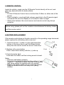
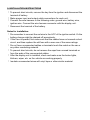
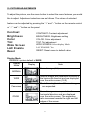
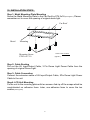
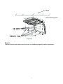
E nglish
ALDINET S.P.A.
VIALE C.COLOMBO, 8
20090 TREZZANO S/N (MI)
ITALY
CONTENTS
Welcome ............................................................................ 1
Introduction ........................................................................ 1
Safety Precautions ............................................................. 2
Package Contents .............................................................. 4
LCD Panel Adjustment ....................................................... 5
Button Functions ................................................................ 6
Remote Control ................................................................ 8
Battery Replacement.......................................................... 8
Installation Instructions....................................................... 9
Troubleshooting .............................................................. 10
Picture Adjustment ...........................................................11
Maintenance ................................................................... 12
Specifications .................................................................... 12
Wiring / Connections......................................................... 13
Installation Steps ............................................................. 15
1
1. WELCOME
Thank you for buying the Roof Mount LCD Monitor. Please read this manual
carefully before using the Roof Mount LCD Monitor in order to get the most out
of all the features and functions. Keep this manual safely , as it can be a valuable
tool in helping you to understand all the Monitor’s capabilities.
2. INTRODUCTION
This is a Roof Mount 15.4" TFT-LCD Color Monitor that can be used as a
stand-alone display, or can be integrated into a mobile multimedia system. The
unit has the following features:
15.4" TFT-LCD color monitor (16:9)
Roof Mount Application
Auto Switch NTSC/PAL
Pixel (dots):1280x3(RGB) x800
Adjustable Color/Contrast/Brightness/Tint
Manual Viewing Angle Adjustment
Vertical Adjustable: up/down<1750
Automotive Startup Protection
IR Remote Control
On Screen Display (OSD)
Size: 384mmx340mm(H) x47mm(HxWxD)
2xAV Input
1xAV Output
IR Transmitter
2
3. SAFETY PRECAUTIONS
The unit is designed for using in DC12V, negative ground battery.
Do not operate the unit in any way other than described within this manual.
Failure to follow the instructions within the manual will invalidate your
warranty.
SAFETY FIRST! Do not install the display where it may (i) obstruct the
driver’s vision, (ii) impair the performance of any of the vehicle’s operating
systems or safety features, including airbags, or (iii) impair the driver’s ability
to safely operate the vehicle.
When using the system, make sure you are firmly secured by your seat belt
to ensure you do not accidentally hit your head on the screen during sudden
braking or other incidents. If you are ever in an accident, injuries can be more
severe if the seat belt is not properly buckled.
Do not attempt to install or service your display by yourself. Installation or
servicing of the display by persons without training and experience in
electronic equipment and automotive accessories may be dangerous and
could expose you to the risk of electric shock or other hazards.
Be careful not to drain the car battery while using the unit with the car engine
stopped. To avoid draining the battery, it is suggested that the vehicle engine
always is running while using the unit.
Do not disassemble or alter the unit in any way. Failure to do so can cause
damage to the unit and invalid the warranty.
Never clean the surface of the screen with chemical solvent or corrosive
detergent, which may cause permanent damage to the TFT LCD screen.
Avoid installing the unit wherever is under direct sunlight or near hot air vent.
Please note that the normal working temperature of the unit is between 0℃
to +50℃. If the internal temperature of the vehicle is extremely high, a short
cooling down period is necessary before operating the unit.
If the temperature inside the car is very low and the monitor is used soon
after switching on the heater, moisture may form on the panel of the unit.
Turn off the unit immediately! Failure to do so may cause the internal
components to short. Allow the unit to rest for about one hour to allow the
condensation to disappear before continue operation.
3
In extremely cold temperatures, the movement of the picture may be slow
and the picture may be dark. It is not a malfunction. The unit will work
normally once it reaches its operating temperature.
Do not drop or hit the LCD panel with a hard object, as it may cause
permanent damage to the LCD panel. Should LCD panel break, avoid
touching glass and fluid. If do, please clean it with plenty of water and ask for
medical attention immediately.
Due to different car specifications, please kindly ensue that the display
monitor is properly located and not obstructing the rear view mirror and
air-conditioning vent.
Use the supplied screws to fix the monitor Metal Mounting Plate.
Kindly refer to authorized dealers if you have any questions.
Before installing this display system, please check with the conformity
of your local traffic rules and regulations.
Changes or modifications not expressly approved by the party responsible for
compliance could void the user’s authority to operate the equipment.
4
4. PACKAGE CONTENTS
Appearance
E
L
A
C
S
1.
0
Parts Name
Quantity
LCD Display
1
IR Remote Control w/Battery
1
Car Power Cable
1
Metal Mounting Plate
1
ST4.2x16
10
CM 4x8
Adhesive foam
User’s Manual
8
8
1
Use only the contents of this package to install. Use of any accessories not
provided with this monitor may result in damage to the display.
Before installing this display system, please check with the conformity
of your local traffic rules and regulations.
5
5.LCD PANEL ADJUSTMENT
Open the LCD panel. Press Open Button to disengage the LCD panel. Pull
the LCD panel outward till the desired viewing angle.
CAUTION:
The LCD display opens to a maximum angle of 175° degrees. Opening it
further than that may cause damages.
②Close the LCD panel.
Close manually until you hear the lock click.
CAUTION:
Make sure that cords and other items do not get caught in the panel when
you close it.
For your safety, be sure to close the LCD panel when not use it.
6
6.BUTTON FUNCTIONS
1. Power Button (
)
2. SOURCE Button
3. Menu - Button
4. Dome Light Switch
5. Display Panel Open Knob
6. Menu + Button
7. ∧ Increase Button
8. ∨ Reduce Button
9. IR Transmitter
10. AV1 IN
1) Power ON/OFF Button[ ]
Press the button on the panel or on the remote control to turn on the power.
Press again, to switch off power.
2) SOURCE Button
Select video input mode.
3) Menu Down Button
Press this button to activate control function OSD, and to select the desired
control function under Menu.
4) Dome Light ON/OFF Switch
When the button is in ON/OFF position, pressing it will turn ON/OFF the dome
light.
When the button is in DOOR position, it will activate the door to switch dome
lights.
7
Note:
This function can be operational only when the red wire of the dome light is
connected to the door sensor.
The dome light will switch off after the car door is closed.
5) Display Panel Open Button
When display is closed, push this button to release the LCD panel.
6) Menu Up Button
Press this button to activate control function OSD, and to select the desired
control function under Menu.
7) ∧ Increase Button
The button is for increasing/changing the feature values under Menu.
8) ∨ Reduce Button
The button is for reducing/changing the feature values under Menu.
9) IR Transmitter
This IR Transmitter is for IR wireless headphone.
10) AV1 IN
8
7. REMOTE CONTROL
Inside the vehicle, simply aim the IR Remote Control directly at the unit, and
press any desired button for better effects.
Notes:
Put the IR Remote Control from no further than 3 Meter on either side of the
sensor.
Direct sunlight or very bright light reduces sensitivity to the IR remote signal
commands. Be sure the display is not located in direct sunlight.
Obstruction between the remote sensor and remote control may disrupt
reception.
Before using, please pull out the insulation sheet between the battery holder
and the remote control.
8. BATTERY REPLACEMENT
If the remote control does not function correctly or the operating range shortened,
please replace the old battery with a new one.
Pull
1. Follow the arrow 1 to slide it to the right toward the
battery, at the same time to pull the battery holder
away from the remote control as arrow 2 instructed.
2. Replace with a new battery.
Place a new lithium battery with the (+) side up.
3. Push the holder back.
Push back the holder until the locking sound is heard.
Notes:
Dispose used battery properly.
Do not misuse battery by shorting the positive “+” and
negative “–” terminal or throw it into fire. Overheating
may cause battery to explode and a fire hazard.
Battery and battery holder can be a choking hazard.
Keep the remote control unit away from young
children.
9
Push
1
2
9. INSTALLATION INSTRUCTIONS
To prevent short circuits, remove the key from the ignition and disconnect the
terminal of battery.
Make proper input and output cable connections for each unit.
Connect the wire harness in the following order: ground wire, battery wire,
ignition wire. Connect the wire harness connector with the display unit.
Reconnect the terminal of the battery.
Notes for installation:
Do remember to connect the red wire to the ACC of the ignition switch. Or the
battery charge might be drained off prematurely.
If the fuse is opened, first make sure that the cables have not caused a short
circuit, and then replace the old fuse with a new one of the same ratings.
Do not have unconnected cables or terminals touch the metal on the car or
any other conducting material.
To prevent short circuits, do not remove the caps from unused terminals or
from the ends of the unconnected cables.
After the display unit is installed, check and make sure the brake lights,
blinkers, wiper, etc. on the vehicle are working properly.
Insulate unconnected wires with vinyl tape or other similar material.
10
10. TROUBLESHOOTING
Problem
No picture when
the display is
turned on.
Blue picture on
the screen.
No function on
the remote
control (or
operating
distance is
shortened).
The picture on
the screen is
dark.
Cause
1. Power wire is
connected improperly
or fuse blown.
2. System cable is not
on right position.
1. Interfered by
short-distanced
strong interference.
Solution
1. Check the power wire
and replace the fuse.
2. Check system cable
or replace a new one.
1. The equipment
locates at a low
temperature area.
2. BRIGHTNESS is set
too dark.
1. This is the
characteristic of LCD
display in low
temperature, it will
restore to normal
brightness after
starting the display for
few minutes.
2. Check BRIGHTNESS
adjustment.
1. Switch on the
headphone.
2. Replace the battery.
3. Remove the blocking
object or move back
to the receiving area.
The reception of signal
will get better when
(E.g. high voltage wire, transformation moving away from
station or aircraft etc…)
Interference.
1. The battery of remote 1. Replace a new battery
with same ratings.
control has
2. Contact with dealer
exhausted.
and replace a new
2. Remote control is
remote control.
defective.
No sound can be 1. Headphone is not
heard from the
switched on.
IR wireless
2. The battery in the
headphone.
headphone is low.
3. There is object
blocking the
transmitting module
or beyond the
effective receiving
area.
11
11. PICTURE ADJUSTMENTS
To adjust the picture, use the menu button to select the menu features you would
like to adjust. Adjustment selections are as follows. The values of selected
feature can be adjusted by pressing the “+” and “–” button on the remote control
or “∧” and“∨” button on the panel.
Contrast
Brightness
Color
Tint
Wide Screen
LAC Enable
Reset
CONTRAST: Contrast adjustment
BRIGHTNESS: Brightness setting
COLOR: Color adjustment
TINT: Tint adjustment
WIDE SCREEN: Select display Mode
LAC ENABLE: Yes
RESET: Reset menu to default value
Display Mode
REMARK: system default is WIDE.
Display
Display
Mode
Note
Normal image (4:3)
NORMAL
WIDE
Panorama
ZOOM
Normal images are expanded uniformly in
the horizontal direction and are displayed
over the entire screen.(16:9)
The left and right sides of Normal images
are expanded.
Normal images are expanded in the
horizontal direction and are displayed
over the entire screen. The expansion
ratio increases towards the right and left
edges of the screen.
12
12. LCD PANEL MAINTENANCE
Wipe off any dust gently with a soft, dry cloth.
The surface is easily scratched; do not rub it with hard objects.
Do not use any chemical solvent, cleaning agent or corrosive detergent to
clean away dirt on the surface of the screen.
13. SPECIFICATIONS
General Specifications
Power Source:
Operating Voltage:
Mechanism:
Display Angle:
Operating Current:
Dome Light:
Operating Temperature:
Storage Temperature:
Car Battery (DC +10.5V ~ +16V)
DC +12V
Manual Open / Close
Vertical Adjustable: Up/Down < 175°
<1.2A(Dome Light Off)
5W x2
-5℃ to +50℃
-20°C to +60°C
13
14.WIRING/CONNECTIONS
1. A/V Output
An auxiliary A/V output is provided to drive an external monitor. This signal
mirrors what’s being shown on the display. The volume function does not affect
the Auxiliary A/V Output.
2. AUX A/V, Input 1(AUX A/V, Input 2)
14
3. Battery + lead (Yellow)
To connect the positive terminal of the car battery.
4. ACC Power Lead (Red)
To ACC power lead powered when engine key position is ACC.
5. Ground Lead (Black)
Connect the lead to a good chassis ground on the car. Make sure the connection
is made to bare metal and is securely fastened using the sheet metal screw
provided.
6. Connector
This is connected to the Overhead Monitor through the 2.4m, Mini-DIN Extension
Cable.
7. Dome Light Wire
This wire connects the built-in Dome Light to the cable from the car’s Dome Light
Switch.
8. Polarity Switch
Please slide to “-” at the left position if your vehicle’s power supply system is
negative; Please slide to “+” at the right position if your vehicle’s power supply
system is positive. The default polarity is negative.
Notes: 1.Please slide it to a side fully.
2.Do not slide this switch after installing the player. Otherwise, it’ll be
damage.
9. AV 1 IN
15
15. INSTALLATION STEPS
Step 1: Metal Mounting Plate Mounting
Screw the Metal Mounting Plate to the Car Roof by ST4.2x16 (See Figure 1). Please
remember not to cover the opening of original dome light.
Car-Roof
Metal
Mounting
Screw to the Car Roof
Mounting Screw
ST4.2x16 *10
(Figure 1)
Step 2: Cable Routing
Pull out the AV Input/Output Cable, 3 Pin Dome Light Power Cable from the
opening of original Dome Light.
Step 3: Cable Connection
Connect the extension cable of AV Input/Output Cable, 3Pin Dome Light Power
Cable to the unit.
Step4: LCD Unit Mounting
Fix the unit to the mounting plate with ten screws. And rip off the scraps which be
conglutinated on adhesive foam. Later, use adhesive foam to cover the ten
screws (See Figure2).
16
Car Roof
Metal Mounting Plate
(Figure 2)
Step 5:
Please check and make sure this unit is installed properly before operation.
17