1
ICP Electronics Inc.
Page 1/35
LCM16A2-002 User’s Manual
A202 Ver 0.0
Author:
Davis Wang
ICP Electronics Inc.
INTRODUCTION
a.
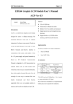
One first display page.
b.
Eight auto-rolling display pages.
c.
One adjustable Watch-Dog-Timer.
d.
Could Daily to turn on or turn off system
automatically.
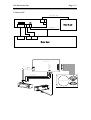
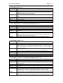
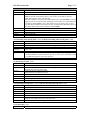
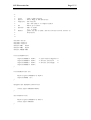
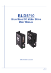
A202 is a LCD Module designed for system to
display messages to outlet. The maximum text
allowed is 16 characters and 2 lines, This
device working under 5V power system and use
a RS232 interface to communicate with system.
Following the ICP Peripheral Communication
e.
Adjustable back-light brightness.
f.
Four GPIO.
g.
One battery-backup real time clock.
h.
Internal OSD for user easy to configure .
i.
Five Programmable Buttons (Four OSD
buttons and One extra function button.)
Protocol (described in Appendix A), A202 has
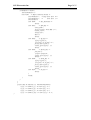
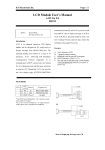
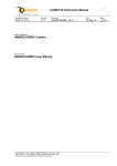
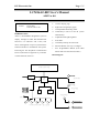
Block Diagram
versatile functions, there are :
LCD 16X2 Characters Display
RS232 BUF
LT1381
CPU
8052
ATX Power Down
SYSTEM RESET
RTC
EEPROM
4 GPIO
SYSTEM POWER
Fn Key Locker
ATX 5V STDBY
5 OSD Switch Button (UP, DOWN, ESC, ENTER, Fn)
Powe Good LED Signal
ICP Electronics Inc.
Page 2/35
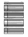
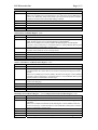
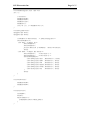
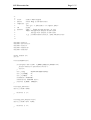
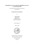
Connect to PC
ATX 5V STANDBY
JP3
JP9
A202
JP5
JS1
JP4
JP6
JP10
Power Supply
JP8
Power Good LED Signal
COM PORT
ATX Switch
ATX POWER
RESET
Mother Board
ATX Power Switch
PC Reset Button
PC Power LED+
5V Stand BY
Mother Board
COM Port
ATX Power Switch
PC Reset Button
PC Power LED+
ATX Power supply
5V
Sta
nd
BY
ICP Electronics Inc.
Page 3/35
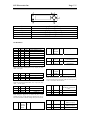
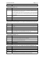
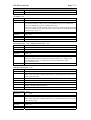
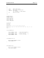
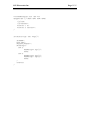
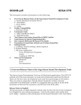
1
2
3
4
5
6
Power LED
Fn Button (Button 4)
Up Button (Button 1)
Enter Button (Button 2)
Down Button (Button 3)
ESC Button (Button 0)
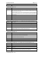
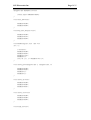
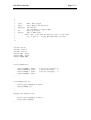
Pin Definition
JS1
1
2
3
4
5
6
7
8
9
10
NC
Tx
Rx
NC
Gnd
NC
NC
NC
NC
NC
Out
In
Float
A202 Output to PC
A202 Input from PC
Inner Connect to Pin 6
Connect to Ground
Inner Connect to Pin 4
Inner Connect to Pin 8
Inner Connect to Pin 7
Float
Float
Note: JS1 uses fixed 1200 Baud Rate, 8 bit, 1 stop bit, no parity
check,±12V Signal.
JP5
1 Power
2
Rx
In
3
Tx
Out
4 Ground
+5VDC out
A202 Input from PC
A202 Output to PC
Ground
Note: JJP5 uses fixed 1200 Baud Rate, 8 bit, 1 stop bit, no parity
check, +5V TTL Signal.
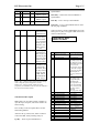
JP3
1 NC
2 Ground
3 Ground
4 Power
JP6
Note: Strongly to suggest user to connect JP3 pin 4 to ATX
StandBy 5V Power, or many functions of A202 like auto-turn-on,
turn-on-now functions could not working when system is turn off.
ATX Bi-Di Normal Open Point
Power
r
Switch
Pin 2
1
Reset
Pin 1
Reset
Pin 2
2
JP8
1
2
1
2
3
4
JP11 1
JP4
1
ATX Bi-Di
Power
r
Switch
Pin 1
Common Point
Power
Good
LED+
NC
Bi-Di
Reset Switch
r
Common Point
Bi-Di Reset Switch Normal
r
Open Point
In
Power Good LED+
Float
Note: A202 use JP8 Pin1 to know System is under Power On or
Power Off, if this pin is not connected, it will cause A202 try to turn
on PC or turn off PC without reference
JP9
Ground
Ground
+5VDC in
2
GPIO0 I/O
Open Drain, weak
Pull High, CMOS I/O
Pin
GPIO1 I/O
“
GPIO2 I/O
“
GPIO3 I/O
“
Fn_Key
In
2 ESC_Key
In
3
In
Up_Key
Connect to A202
Button 4 input
Connect to A202
Button 0 input
Connect to A202
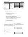
ICP Electronics Inc.
4 Enter_Key
In
5 Down_Key
In
6
Ground
Powe
r
Page 4/35
Button 1 input
Connect to A202
Button 2 input
Connect to A202
Button 3 input
Ground
alpha-number.
Down Key : Select Down forward Manuel or
alpha-number.
ESC Key : Exit or Escape current Manuel.
Enter Key : Active current Manuel Item or Enter
the next page of Manuel.
JP10
Pin 1, 2
Open
Short
Pin 3, 4
Open
Short
Press Fn_Key
Could Active All
OSD Function
Press Fn_Key
Could only
Active OSD
Turn_On/Off and
Reset_Sys two
Function , the
others is been
lock.
Press Fn_Key
Could Active
OSD. (Fn_Key is
a special key and
been reserved to
A202 to Open
OSD use only.)
Fn_Key become
a normal key and
released for
system use, Press
Fn_Key will no
longer to enter
OSD, and be
treated like the
other 4 keys.
There are about 31 items of OSD Manuel list in the
OSD, press Fn_Key will appear OSD on the LCD
which would look like :
> TURN ON/OFF NOW
RESET SYS NOW
# Display
1 TURN ON/OFF NOW
2 RESET SYS NOW
3 EDIT FIRST PAGE
4 EDIT AUTO PAGE0
Note 1 : Pin 1, 2 Jumper is used to prevent end user to change
A202’s setting after system is shipped out to end user.
Note 2 : Pin 3, 4 Jumper specially useful for the system
programmer, who would like have his own OSD and would like to
have whole control of the five buttons.
OSD Function Description
Note: Before to use OSD of A202, remember to
open JP10 pin1 and pin2, which will enable the
OSD working.
Press Fn Key on the front panel then will enter
OSD setting Manuel.
A202 use the Up, Down, ESC, Enter 4 button to
control the OSD, mostly meaning of keys is
Up Key : Select Up forward Manuel or
5
6
7
8
9
10
11
12
EDIT AUTO PAGE1
EDIT AUTO PAGE2
EDIT AUTO PAGE3
EDIT AUTO PAGE4
EDIT AUTO PAGE5
EDIT AUTO PAGE6
EDIT AUTO PAGE7
FIRST PAGE ON/OFF
13 AUTO PAGE0 ON/OFF
14
15
16
17
18
19
AUTO PAGE1 ON/OFF
AUTO PAGE2 ON/OFF
AUTO PAGE3 ON/OFF
AUTO PAGE4 ON/OFF
AUTO PAGE5 ON/OFF
AUTO PAGE6 ON/OFF
Description
Turn on or turn off system
now
Reset system now
Edit the content of the
First_Display_Page, This
Page will display only one
time and firstly when system
is power on, but if
First_Page (item 12) is turn
off , there will no display of
this page, this page will be
retained depend the
First_Page_Timer (item 22)
setting.
Edit the content of the
Auto_Display_Page_0,
This page will display
automatically if the
Auto_Page0 (item 13) is
turn On and Autodisplay
(item 21) is turn On, this
page will be retained
depend the
Auto_Page_Timer setting.
Same as item 4
Same as item 4
Same as item 4
Same as item 4
Same as item 4
Same as item 4
Same as item 4
Enable or Disable First
Page to be displayed
Enable or Disable Page0 to
be displayed
Same as item 13
Same as item 13
Same as item 13
Same as item 13
Same as item 13
Same as item 13
ICP Electronics Inc.
20 AUTO PAGE7 ON/OFF
21 AUTODISPLAY ON/OFF
22 FIRSTPAGE TIMER
23 AUTO PAGE TIMER
24 WATCH DOG TIMER
25 WATCH DOG ON/OFF
26 SET ShtDwn TIMER
Page 5/35
Same as item 13
Globally to Enable or
Disable all Auto Page to be
displayed.
Setup the time of First Page
will be displayed
Setup the time of each Auto
Page to be displayed
Setup the count down timer
of WatchDog
Enable or Disable the
WatchDog
Setup the Daily Tme to
27 AUTO ShtDwn ON/OFF
28 SET TurnOn Timer
29 AUTO TurnOn ON/OFF
30 SET CLOCK TIMER
31 SET BACK LIGHT
Turn Off the system
Enable or Disable the Auto
Shutdown function
Setup the Daily Time to
Turn On the System
Enable or Disable Auto
Turn On function
Setup A202 RTC (real time
clock)
Setup the Brightness of
Back Light
The working flow of A202 :
Power_On_Initialize();
If(System_is_Off ) Turn_On_System();
If(First_Display_is_Turn_On)Display_First_Display_Page() until First_Page_Time_Out();
While(1){
If(AutoDisplay_is_Turn_On){
If(Auto_Display_Page_n_is_Turn_On){
Display_Auto_Page_n() until Auto_Display_Time_Out;
Next_auto_display_page();
If(Auto_Display_index > Page7)Auto_Display_index=Page0;
}
}
if(WDT_is_turn_on && WDT_is_time_out)Reset_System();
if(Auto_ShutDown_is Turn_On && ShutDown_Timer_is_Arrive)ShutDown_System();
if(Auto_TurnOn_is_Turn_On && TurnOn_Timer_is_Arrive)Turn_On_System();
if(Fn_Key_is_Pressed && Fn_Key_is_not_Locked){
if(OSD_is_not_Locked)Enter_OSD_item0_to_item31();
else Enter_OSD_item0_to_item1();
}
if(Rs232IsAvailable)Call_A202_Protocol();
if(Key_Pressed)Report_Key_Status();
}
How to use software to Displaying Messages on
LCD
0x4D
0x0D
The Leading Code.
Clear LCD Command.
Use Rs232 (B1200, N, 8, 1) PC Interface, A202 is
Send to A202: 0x4D 0x0C 0x00 0x03 0x49 0x43
able to display most of the characters you can find
0x50
on the ASCII code. Here is an example to display
Where:
text messages on the LCD.
Send to A202: 0x4D 0x7C 0x00 (optional)
Where :
0x4D
The Leading Code.
0x7C
Switch All Auto Display ON/OFF
Command.
0x00
Turn OFF
Send to A202: 0x4D 0x0D (optional)
Where :
0x0C
0x00
Display Character on LCD
Characters displayed on line0
(first line on LCD)
0x03
3 characters will be displayed
0x49 0x43 0x50
ASCII codes for ICP
The A202 first clear the screen then the text ICP is
display on the upper-left corner of LCD look like
ICP
ICP Electronics Inc.
How to use buttons
When buttons on A202 is been pressed or
released, A202 will automatically to transmit
electric signal (RS232 code) to PC at once like.
When button 0 (ESC Button) be pressed :
A202 send to PC : 0x53 0x05 0x00 0x01;
Where
0x53
The leading code of A202.
0x05
Report Button Status.
0x00
Button data byte 0.
0x01
Button data byte 1, the bit 0 of byte 1
respect the button 0 (ESC Button) is pressed.
When button 0 (ESC Button) be released after
pressed :
A202 send to PC : 0x53 0x05 0x00 0x00;
Where
0x53
The leading code of A202.
0x05
Report Button Status.
0x00
Button data byte 0.
0x00
Button data byte 1, the bit 0 of byte 1
respect the button 0 (ESC Button) is released.
Please Note : if the internal OSD is enabled
(JP10 pin 1_2, pin 3_4 is open) and Fn has been
pressed and A202 is then enter internal OSD
(embedded OSD), then in this status, all button’s
status will be captured by A202 and no transmit to
PC until leave OSD.
Please reference Appendix A to know more useful
instructions of A202, and the Demo Program is on
Appendix D.
Page 6/35
ICP Electronics Inc.
CAUTION : Danger of explosion if battery is incorrectly replaced.
Replace only with the same or equivalent type recommended by the
manufacturer. Dispose of used batteries according to the manufacturer
instruction.
Page 7/35
ICP Electronics Inc.
Page 8/35
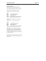
Appendix A
The ICP Peripheral Communication Protocol Version 0.02
History
2001/03/20
2001/10/29
2002/12/13
Version 0.01
Version 0.02 Addition Command Turn On/Off Back Light (0x5E)
Version 0.03
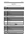
Get ID : 0x00 and Report ID : 0x01
Direction
PC → A202
Command
0x4D 0x00
Explain
0x4D=Leading Code of PC; 0x00=Get ID Command
Example
0x4D 0x00
Response
A202 → PC
Command
0x53 0x01 0xXX 0xYY
Explain
0x53=Leading Code of A202; 0x01=Report ID Command; 0xXXYY=ID;
Example
0x53 0x01 0x00 0xCA (Board ID= 0x00CA ---A202)
Get Button Status : 0x06 and Report Button Status : 0x05
Direction
PC → A202
Command
0x4D 0x06
Explain
0x4D=Leading Code of PC; 0x06=Get Button Status Command
Example
0x4D 0x06
Response
A202 → PC
Command
0x53 0x05 0xXX 0xYY
Explain
0x53=Leading Code of A202; 0x05=Report Button Status Command;
0xXXYY=Buttons on/off , XXYY<15:0>=Button<15:0>, 1=Pressed, 0=Release
Bit0=Esc_Button, Bit1=Up_Button, Bit2=Enter_Button, Bit3=Down_Button,
Bit4=Fn_Button.
Example
0x53 0x05 0x00 0x11 (Esc_Button and Fn_Button is Pressed)
0x53 0x05 0x00 0x00 (All Key are released)
Note
Report Button Status Command will automatically report to PC when button is
pressed or released.
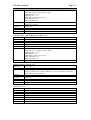
Get Protocol Version : 0x07 and Report Protocol Version : 0x08
Direction
PC → A202
Command
0x4D 0x07
Explain
0x4D=Leading Code of PC; 0x07=Get Protocol Version Command
Example
0x4D 0x07
Response
A202 → PC
Command
0x53 0x08 0xXX 0xYY
Explain
0x53=Leading Code of A202; 0x08=Report Protocol Version Command; 0xXX=Class
Number; 0xYY=Version Number
Example
0x53 0x08 0x00 0x03 (Class 00, Version 03)
Set Clock Time : 0x09
Direction
PC → A202
Command
0x4D 0x09 0xYY 0xMM 0xDD 0xHH 0xmm 0xSS
ICP Electronics Inc.
Explain
Example
Response
Command
Explain
Example
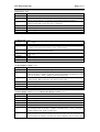
Get Clock Time
Direction
Command
Explain
Example
Response
Command
Explain
Example
Page 9/35
0x4D=Leading Code of PC; 0x09=Set Clock Time Command;
0xYY=Year (00~99) Map to (2000 ~ 2099)
0xMM=Month (01 ~ 12)
0xDD=Day (01 ~ 31)
0xHH=Hour in 24Hr Type (00~23)
0xmm=Minute (00~59)
0xSS=Second (00~59)
0x4D 0x09 0x00 0x0C 0x07 0x0D 0x28 0x05 (Set A202 RTC (real time clock) on
2000/12/07 13:40:05)
A202 → PC
0xFA
Acknowledge OK
0xFA
: 0x0B and Report Clock Time : 0x0A
PC → A202
0x4D 0x0B
0x4D=Leading Code of PC; 0x0B=Get Clock Time Command
0x4D 0x0B
A202 →PC
0x53 0x0A 0xYY 0xMM 0xDD 0xHH 0xmm 0xSS
0x53=Leading Code of A202; 0x0A=Report Clock Time Command;
0xYY=Year (00 ~ 99) Map to (2000 ~ 2099)
0xMM=Month (01 ~ 12)
0xDD=Day (01 ~ 31)
0xHH=Hour in 24Hr Type (00~23)
0xmm=Minute (00~59)
0xSS=Second (00~59)
0x53 0x0A 0x00 0x0C 0x07 0x0D 0x28 0x09 (Report Time 2000/12/07 13:40:09)
Display Character On LCD: 0x0C
Direction
PC → A202
Command
0x4D 0x0C 0x0L 0x0N 0xCC1 ~ 0xCC16
Explain
0x4D=Leading Code of PC; 0x0C=Display Character On LCD Command; 0x0L=0x00
(Line 0) or 0x01 (Line 1); 0x0N=N Character (1~16), no more than 16 characters;
0xCCn=ASCII Code of Characters,
Example
0x4D 0x0C 0x01 0x03 0x49 0x43 0x50 (Line 1, 3 Characters, ICP)
Response
A202 →PC
Command
0xFA
Explain
Acknowledge OK
Example
0xFA
Clear LCD : 0x0D
Direction
PC → A202
Command
0x4D 0x0D
Explain
0x4D=Leading Code of PC; 0x0D=Clear LCD Command
Example
0x4D 0x0D
Response
A202 →PC
Command
0xFA
Explain
Acknowledge OK
Example
0xFA
ICP Electronics Inc.
Page 10/35
Cursor Go to : 0x54
Direction
PC → A202
Command
0x4D 0x54 0xXX 0xYY
Explain
0x4D=Leading Code of PC; 0x54=Cursor Go to Command; 0xXX=X (column)
Position of LCD, from 0 to 15; 0xYY=Y (line) Position of LCD, from 0 to 1.
Example
0x4D 0x54 0x00 0x00 (cursor go to line 0, column 0)
0x4D 0x54 0x03 0x01 (cursor go to line 1, column 3))
Response
A202 →PC
Command
0xFA
Explain
Acknowledge OK
Example
0xFA
Set Back Light : 0x5E
Direction
PC → A202
Command
0x4D 0x5E 0x0L
Explain
0x4D=Leading Code of PC; 0x5E=Set Back Light Command; 0x0L=Back Light
Brightness Level from 0x00 to 0x04, 0=Dark, 4=Fully Bright
Example
0x4D 0x5E 0x01 ( Set Back Light Level on level 1)
0x4D 0x5E 0x00 ( Turn Off Back Light)
Response
A202 →PC
Command
0xFA
Explain
Acknowledge OK
Example
0xFA
Set First Display Content : 0x70
Direction
PC → A202
Command
0x4D 0x70 0x0S 0x0N 0xCC1 ~ 0xCCn
Explain
0x4D=Leading Code of PC; 0x70=Set First Display Content Command; 0x0S=Display
Enable or Disable, 1=Enable, 0=Disable; 0x0N=Total Number of Characters to write,
from 1 to 32; 0xCC1 ~ 0xCCn=Display Content in ASCII code;
Example
0x4D 0x70 0x01 0x03 0x49 0x43 0x50 (Setup First Display Content, The Display is
Enable, Display ICP on the Line 0, the other are white space)
Response
A202 →PC
Command
0xFA
Explain
Acknowledge OK
Example
0xFA
Get First Display Content : 0x71 and Report First Display Content : 0x72
Direction
PC → A202
Command
0x4D 0x71
Explain
0x4D=Leading Code of PC; 0x71=Get First Display Content Command;
Example
0x4D 0x71
Response
A202 →PC
Command
0x53 0x72 0x0S 0xCC1 ~ 0xCC32
Explain
0x53=Leading Code of A202; 0x72=Report First Display Content Command;
0x0S=Display Enable or Disable, 1=Enable, 0=Disable; 0xCC1 ~ 0xCC32=Display
Content in ASCII code, Totally 32 characters;
Example
0x53 0x72 0x01 0x49 0x43 0x50 0x20 0x20 0x20 0x20 0x20 0x20 0x20 0x20 0x20 0x20
0x20 0x20 0x20 0x49 0x43 0x50 0x20 0x20 0x20 0x20 0x20 0x20 0x20 0x20 0x20 0x20
0x20 0x20 0x20 (First Display is Enable, the content is ICP, the other are white spaces)
ICP Electronics Inc.
Page 11/35
Set First Display Retain : 0x73
Direction
PC → A202
Command
0x4D 0x73 0xHH 0xLL
Explain
0x4D=Leading Code of PC; 0x73=Set First Display Retain Command;
0xHHLL=Seconds of First Display to be Retained on LCD, from 0000 to 9999 sec.
0xHH=high eight bits, 0xLL=low eight bits.
Example
0x4D 0x73 0x00 0x10 (Set First Display Retain 0x0010=16 seconds displayed on
LCD);
Response
A202 →PC
Command
0xFA
Explain
Acknowledge OK
Example
0xFA
Get First Display Retain : 0x74 and Report First Display Retain : 0x75
Direction
PC → A202
Command
0x4D 0x74
Explain
0x4D=Leading Code of PC; 0x74=Get First Display Retain Command;
Example
0x4D 0x74
Response
A202 →PC
Command
0x53 0x75 0xHH 0xLL
Explain
0x53=Leading Code of A202; 0x75=Report First Display Retain Command;
0xHHLL=Seconds of First Display to be Retained on LCD, from 0000 to 9999 sec.
0xHH=high eight bits, 0xLL=low eight bits.
Example
0x53 0x75 0x00 0x10 (The First Display Retain Time is 0x0010=16 seconds)
Set Auto Display Content : 0x76
Direction
PC → A202
Command
0x4D 0x76 0x0P 0x0S 0x0N 0xCC1 ~ 0xCCn
Explain
0x4D=Leading Code of PC; 0x76=Set Auto Display Content Command; 0x0P=Which
Page to be Set, from 0 to 7; 0x0S=Display Enable or Disable, 1=Enable, 0=Disable;
0x0N=Total Number of Characters to write, from 1 to 32; 0xCC1 ~ 0xCCn=Display
Content in ASCII code;
Example
0x4D 0x76 0x02 0x01 0x03 0x49 0x43 0x50 (Set Auto Display Page 2, Display is
Enable, 3 character, Display ICP on the Line 0, the other are white space)
Response
A202 →PC
Command
0xFA
Explain
Acknowledge OK
Example
0xFA
Get Auto Display Content : 0x77 and Report Auto Display Content : 0x78
Direction
PC → A202
Command
0x4D 0x77 0x0P
Explain
0x4D=Leading Code of PC; 0x77=Get Auto Display Content Command; 0x0P=Which
Page, from 0 to 7;
Example
0x4D 0x77 0x02 (Get Auto Page 2 content)
Response
A202 →PC
Command
0x53 0x78 0x0P 0x0S 0xCC1 ~ 0xCC32
Explain
0x53=Leading Code of A202; 0x78=Report First Display Content Command;
0x0P=Which page, from 0 to 7; 0x0S=Display Enable or Disable, 1=Enable,
0=Disable; 0xCC1 ~ 0xCC32=Display Content in ASCII code, Totally 32 characters;
Example
0x53 0x78 0x02 0x01 0x49 0x43 0x50 0x20 0x20 0x20 0x20 0x20 0x20 0x20 0x20 0x20
0x20 0x20 0x20 0x20 0x20 0x20 0x20 0x20 0x20 0x20 0x20 0x20 0x20 0x20 0x20 0x20
0x20 0x20 0x20 0x20 (Report Auto Display Page 2 content, Display is Enable, the
ICP Electronics Inc.
Page 12/35
content is ICP, the other are white spaces)
Set Auto Display Page Retain : 0x79
Direction
PC → A202
Command
0x4D 0x79 0xHH 0xLL
Explain
0x4D=Leading Code of PC; 0x79=Set Auto Display Page Retain Command;
0xHHLL=Seconds of Auto Display page to be Retained on LCD, from 0000 to 9999 sec.
0xHH=high eight bits, 0xLL=low eight bits.
Example
0x4D 0x79 0x00 0x10 (Set Auto Display Retain 0x0010=16 seconds displayed on
LCD);
Response
A202 →PC
Command
0xFA
Explain
Acknowledge OK
Example
0xFA
Get Auto Display Page Retain : 0x7A and Report Auto Display Page Retain : 0x7B
Direction
PC → A202
Command
0x4D 0x7A
Explain
0x4D=Leading Code of PC; 0x7A=Get Auto Display Page Retain Command;
Example
0x4D 0x7A
Response
A202 →PC
Command
0x53 0x7B 0xHH 0xLL
Explain
0x53=Leading Code of A202; 0x7B=Report Auto Display Page Retain Command;
0xHHLL=Seconds of First Display to be Retained on LCD, from 0000 to 9999 sec.
0xHH=high eight bits, 0xLL=low eight bits.
Example
0x53 0x7B 0x00 0x10 (The Auto Display Retain Time is 0x0010=16 seconds)
Set Auto Display Page Globally ON/OFF : 0x7C
Direction
PC → A202
Command
0x4D 0x7C 0x0N
Explain
0x4D=Leading Code of PC; 0x7C=Set Auto Display Page Globally ON/OFF
Command; 0x0N=Switch of Display Auto Page, 0x01=ON, 0x00=OFF.
This Command is the first priority to enable or disable all the Enabled Auto Pages to be
displayed. It is necessary when system want to display message but do not like Auto
Pages to cover with after, switch OFF(or disable) will prevent this situation
Example
0x4D 0x7C 0x00 (Set Auto Display Globally OFF)
0x4D 0x7C 0x01 (Set Auto Display Globally ON)
Response
A202 →PC
Command
0xFA
Explain
Acknowledge OK
Example
0xFA
Get Auto Display Page Globally ON/OFF status : 0x7D and Report Auto Display Page Globally
ON/OFF status : 0x7E
Direction
PC → A202
Command
0x4D 0x7D
Explain
0x4D=Leading Code of PC; 0x7D=Get Auto Display Page Globally ON/OFF status
Command;
Example
0x4D 0x7D
Response
A202 →PC
Command
0x53 0x7E 0x0N
Explain
0x53=Leading Code of A202; 0x7E=Report Auto Display Page Globally ON/OFF
status Command; 0x0N=Switch of Display Auto Page, 0x01=ON, 0x00=OFF.
ICP Electronics Inc.
Example
Page 13/35
0x53 0x7E 0x00 (The Globally Auto Page Display Switch is OFF)
Set Auto Shut Down Timer : 0x7F
Direction
PC → A202
Command
0x4D 0x7F 0xHH 0xMM
Explain
0x4D=Leading Code of PC; 0x7F=Set Auto Shut Down Timer Command; 0xHH=The
hour to Auto Shut Down the system, from 0 to 23 (24h mode); 0xMM=The minute to
Auto Shut Down the system, from 0 to 59;
After this command is setup, A202 will to compare the RTC in A202 with 0xHH:0xMM
(formed to hh:mm), if RTC is arrive to hh:mm and Auto Shut Down Switch (command
0x82) is Turn ON, then A202 will try to turn off system by switch ON_OFF ATX Power
switch one time.
Example
0x4D 0x7F 0x0C 0x0A (Set the Auto Shut Down Timer to 12:10 to shut down system
daily)
Response
A202 →PC
Command
0xFA
Explain
Acknowledge OK
Example
0xFA
Get Auto Shut Down Timer Setting Value : 0x80 and Report Auto Shut Down Timer Setting Value :
0x81
Direction
PC → A202
Command
0x4D 0x80
Explain
0x4D=Leading Code of PC; 0x80=Get Auto Shut Down Timer Setting Value
Command;
Example
0x4D 0x80
Response
A202 →PC
Command
0x53 0x81 0xHH 0xMM
Explain
0x53=Leading Code of A202; 0x81=Report Auto Shut Down Timer Setting Value
Command; 0xHH=The hour to Auto Shut Down the system, from 0 to 23 (24h mode);
0xMM=The minute to Auto Shut Down the system, from 0 to 59;
Example
0x53 0x81 0x0B 0x0A (The Auto Shut Down Timer is set on 12:10)
Set Auto Shut Down ON/OFF : 0x82
Direction
PC → A202
Command
0x4D 0x82 0x0N
Explain
0x4D=Leading Code of PC; 0x82=Set Auto Shut Down ON/OFF Command;
0x0N=Switch of Auto Shut Down, 0x01=ON, 0x00=OFF.
Example
0x4D 0x82 0x00 (Set Auto Shut Down OFF)
0x4D 0x82 0x01 (Set Auto Shut Down ON)
Response
A202 →PC
Command
0xFA
Explain
Acknowledge OK
Example
0xFA
Get Auto Shut Down ON/OFF status : 0x83 and Report Auto Shut Down ON/OFF status : 0x84
Direction
PC → A202
Command
0x4D 0x83
Explain
0x4D=Leading Code of PC; 0x83=Get Auto Shut Down ON/OFF status Command;
Example
0x4D 0x83
Response
A202 →PC
Command
0x53 0x84 0x0N
Explain
0x53=Leading Code of A202; 0x84=Report Auto Shut Down ON/OFF status
Command; 0x0N=Switch of Auto Shut Down, 0x01=ON, 0x00=OFF.
ICP Electronics Inc.
Example
Page 14/35
0x53 0x84 0x00 (The Auto Shut Down Switch is OFF)
Set Auto TurnOn Timer : 0x85
Direction
PC → A202
Command
0x4D 0x85 0xHH 0xMM
Explain
0x4D=Leading Code of PC; 0x85=Set Auto Shut Down Timer Command; 0xHH=The
hour to Auto Turn On the system, from 0 to 23 (24h mode); 0xMM=The minute to Auto
Turn On the system, from 0 to 59;
After this command is setup, A202 will to compare the RTC in A202 with 0xHH:0xMM
(formed to hh:mm), if RTC is arrive to hh:mm and Auto Turn On Switch (command
0x88) is Turn ON, then A202 will try to turn on system by switch ON_OFF ATX Power
switch one time.
Example
0x4D 0x85 0x07 0x1E (Set the Auto Turn On Timer to 07:30 to turn on system daily)
Response
A202 →PC
Command
0xFA
Explain
Acknowledge OK
Example
0xFA
Get Auto Turn On Timer Setting Value : 0x86 and Report Auto Turn On Timer Setting Value : 0x87
Direction
PC → A202
Command
0x4D 0x86
Explain
0x4D=Leading Code of PC; 0x86=Get Auto Turn On Timer Setting Value Command;
Example
0x4D 0x86
Response
A202 →PC
Command
0x53 0x87 0xHH 0xMM
Explain
0x53=Leading Code of A202; 0x87=Report Auto Turn On Timer Setting Value
Command; 0xHH=The hour to Auto Turn On the system, from 0 to 23 (24h mode);
0xMM=The minute to Auto Turn On the system, from 0 to 59;
Example
0x53 0x87 0x07 0x1E (The Auto Turn On Timer is set on 07:30)
Set Auto Turn On ON/OFF : 0x88
Direction
PC → A202
Command
0x4D 0x88 0x0N
Explain
0x4D=Leading Code of PC; 0x88=Set Auto Turn On ON/OFF Command;
0x0N=Switch of Auto Turn On, 0x01=ON, 0x00=OFF.
Example
0x4D 0x88 0x00 (Set Auto Turn On OFF)
0x4D 0x88 0x01 (Set Auto Turn On ON)
Response
A202 →PC
Command
0xFA
Explain
Acknowledge OK
Example
0xFA
Get Auto Turn On ON/OFF status : 0x89 and Report Auto Turn On ON/OFF status : 0x8A
Direction
PC → A202
Command
0x4D 0x89
Explain
0x4D=Leading Code of PC; 0x89=Get Auto Turn On ON/OFF status Command;
Example
0x4D 0x89
Response
A202 →PC
Command
0x53 0x8A 0x0N
Explain
0x53=Leading Code of A202; 0x8A=Report Auto Turn On ON/OFF status
Command; 0x0N=Switch of Auto Turn On, 0x01=ON, 0x00=OFF.
Example
0x53 0x8A 0x00 (The Auto Turn On Switch is OFF)
Set Watch Dog Timer : 0x8B
ICP Electronics Inc.
Direction
Command
Explain
Example
Response
Command
Explain
Example
Page 15/35
PC → A202
0x4D 0x8B 0xHH 0xLL
0x4D=Leading Code of PC; 0x8B=Set Watch Dog Timer Command;
0xHHLL=Seconds of Watch Dog Timer to start count to, from 0000 to 9999 sec.
0xHH=high eight bits, 0xLL=low eight bits.
After this command is setup and if the Watch Dog Switch (command 0x8E) is turn ON,
A202 will start to count up this timer, during this period, if there is no Clear Watch Dog
Command (command 0x91) come in, then A202 will start to Reset system by Turn
ON_OFF the Reset Button of the system one time, and then disable Watch Dog Timer by
turn off the Watch Dog Switch Command (command 0x8E);
0x4D 0x8B 0x02 0x58 (Set the Watch Dog Timer to 0x0258=600 seconds)
A202 →PC
0xFA
Acknowledge OK
0xFA
Get Watch Dog Timer Setting Value : 0x8C and Report Watch Dog Timer Setting Value : 0x8D
Direction
PC → A202
Command
0x4D 0x8C
Explain
0x4D=Leading Code of PC; 0x8C=Get Watch Dog Timer Setting Value Command;
Example
0x4D 0x8C
Response
A202 →PC
Command
0x53 0x8D 0xHH 0xLL
Explain
0x53=Leading Code of A202; 0x8D=Report Watch Dog Timer Setting Value
Command; 0xHHLL=Seconds of Watch Dog Timer to start count to, from 0000 to 9999
sec. 0xHH=high eight bits, 0xLL=low eight bits.
Example
0x53 0x8D 0x02 0x58 (The Watch Dog Timer is set on 0x0258=600 seconds)
Set Watch Dog ON/OFF : 0x8E
Direction
PC → A202
Command
0x4D 0x8E 0x0N
Explain
0x4D=Leading Code of PC; 0x8E=Set Watch Dog ON/OFF Command; 0x0N=Switch
of Watch Dog, 0x01=ON, 0x00=OFF.
Example
0x4D 0x8E 0x00 (Set Watch Dog OFF)
0x4D 0x8E 0x01 (Set Watch Dog ON)
Response
A202 →PC
Command
0xFA
Explain
Acknowledge OK
Example
0xFA
Get Watch Dog ON/OFF status : 0x8F and Report Watch Dog ON/OFF status : 0x90
Direction
PC → A202
Command
0x4D 0x8F
Explain
0x4D=Leading Code of PC; 0x8F=Get Watch Dog ON/OFF status Command;
Example
0x4D 0x8F
Response
A202 →PC
Command
0x53 0x90 0x0N
Explain
0x53=Leading Code of A202; 0x90=Report Watch Dog ON/OFF status Command;
0x0N=Switch of Watch Dog, 0x01=ON, 0x00=OFF.
Example
0x53 0x90 0x00 (The Watch Dog Switch is OFF)
Clear Watch Dog : 0x91
Direction
PC → A202
ICP Electronics Inc.
Command
Explain
Example
Response
Command
Explain
Example
Page 16/35
0x4D 0x91
0x4D=Leading Code of PC; 0x91=Clear Watch Dog Command;
Note: This Command will clear Watch Dog to zero, which will prevent Watch Dog to
count to over Watch Dog Timer and reset the system. System must period to send this
command to A202 in time when the Watch Dog is enabled.
0x4D 0x91
A202 →PC
0xFA
Acknowledge OK
0xFA
Write Data to LCD Data Register : 0x92
Direction
PC → A202
Command
0x4D 0x92 0xNN
Explain
0x4D=Leading Code of PC; 0x92= Write Data to LCD Data Register Command;
0xNN, the data will be write to the Data Register of LCD Module.
Note: This Command will write the 0xNN to the Data Register of LCD Module
Controller, which will directly to control the behaviors of LCD Module, Detail please
reference Hitachi LCD Module Controller Spec.
Example
0x4D 0x92 0x49 (Write 0x49 to LCD Module Data Register, which will cause LCD to
display I (0x49) character on its current position)
Response
A202 →PC
Command
0xFA
Explain
Acknowledge OK
Example
0xFA
Write Control Data to LCD Instruction Register : 0x93
Direction
PC → A202
Command
0x4D 0x93 0xNN
Explain
0x4D=Leading Code of PC; 0x93= Write Control Data to LCD Instruction Register
Command; 0xNN, the control data will be written to the Instruction Register of LCD
Module.
Note: This Command will write the 0xNN to the Instruction Register of LCD Module
Controller, which will directly to control the behaviors of LCD Module, Detail please
reference Hitachi LCD Module Controller Spec.
Example
0x4D 0x93 0x01 (Write 0x01 to LCD Module Instruction Register, which will cause
LCD to Clear Display)
Response
A202 →PC
Command
0xFA
Explain
Acknowledge OK
Example
0xFA
Read Data from LCD Data Register : 0x94 and Report Data from LCD Data Register : 0x95
Direction
PC → A202
Command
0x4D 0x94
Explain
0x4D=Leading Code of PC; 0x93=Read Data from LCD Instruction Register
Command;
Note: This Command will Read from the Data Register of LCD Module Controller,
which will directly to control the behaviors of LCD Module, Detail please reference
Hitachi LCD Module Controller Spec.
Example
0x4D 0x94
Response
A202 →PC
Command
0x53 0x95 0xNN
Explain
0x53=Leading Code of A202; 0x95= Report Data from LCD Data Register
ICP Electronics Inc.
Example
Page 17/35
Command; 0xNN=The data in Data Register of LCD Module;
0x53 0x95 0x49 (Character I (0x49) now is on current display position now)
Set GPIO : 0x96
Direction
PC → A202
Command
0x4D 0x96 0x0P
Explain
0x4D=Leading Code of PC; 0x96=Set GPIO Command; 0x0P, the GPIO Data, which
will be latch to GPIO, 1=High, 0=Low, bit0=GPIO0(JP9, pin1), bit1=GPIO1(JP9,
pin2), bit2=GPIO2(JP9, pin3), bit3=GPIO3(JP9, pin4)
Note: The 4 GPIO provided by A202 on JP9 are belong to weak pull high, open drain,
bi-direction CMOS I/O pin, detail description please reference to Winbond W78E54B
Controller Spec. IO Port 4.
Example
0x4D 0x96 0x01 (Turn On GPIO0 and Turn OFF GPIO1, 2, 3 at the same time)
Response
A202 →PC
Command
0xFA
Explain
Acknowledge OK
Example
0xFA
Read GPIO status : 0x97 and Report GPIO status : 0x98
Direction
PC → A202
Command
0x4D 0x97
Explain
0x4D=Leading Code of PC; 0x97=Read GPIO status Command;
Example
0x4D 0x97
Response
A202 →PC
Command
0x53 0x98 0x0P
Explain
0x53=Leading Code of A202; 0x98= Report GPIO status Command; 0x0P, the GPIO
Status Data, which reflect the real status of GPIO outside now, 1=High, 0=Low,
bit0=GPIO0(JP9, pin1), bit1=GPIO1(JP9, pin2), bit2=GPIO2(JP9, pin3),
bit3=GPIO3(JP9, pin4)
Example
0x53 0x98 0x03 (GPIO0, 1 is high, GPIO2, 3 is low)
Shut Down System now : 0x99
Direction
PC → A202
Command
0x4D 0x99
Explain
0x4D=Leading Code of PC; 0x99=Shut Down System now Command;
Note : After receipt this command, A202 will try to short ATX Power Switch once to
cause system shut down.
Example
0x4D 0x99
Response
A202 →PC
Command
0xFA
Explain
Acknowledge OK, but, because system is shut down now, so system should not receive
this Ack, except that system still alive.
Example
0xFA
Reset System now : 0x9A
Direction
PC → A202
Command
0x4D 0x9A
Explain
0x4D=Leading Code of PC; 0x9A=Reset System now Command;
Note : After receipt this command, A202 will try to short Reset Switch once to cause
system to enter reset.
Example
0x4D 0x9A
Response
A202 →PC
Command
0xFA
Explain
Acknowledge OK, but, because system is been reset now, so system should not receive
ICP Electronics Inc.
Example
Page 18/35
this Ack, except that system still not been reset successfully.
0xFA
Cursor ON/OFF : 0x9B
Direction
PC → A202
Command
0x4D 0x9B 0x0S
Explain
0x4D=Leading Code of PC; 0x9B=Cursor ON/OFF Command; 0x0S=ON/OFF
Switch, 0x00=OFF, 0x01=ON;
Example
0x4D 0x9B 0x01 (Cursor On)
0x4D 0x9B 0x00 (Cursor Off)
Response
A202 →PC
Command
0xFA
Explain
Acknowledge OK
Example
0xFA
Cursor Blinking ON/OFF : 0x9C
Direction
PC → A202
Command
0x4D 0x9C 0x0S
Explain
0x4D=Leading Code of PC; 0x9C=Cursor Blinking ON/OFF Command;
0x0S=ON/OFF Switch, 0x00=OFF, 0x01=ON;
Example
0x4D 0x9C 0x01 (Cursor Blinking On)
0x4D 0x9C 0x00 (Cursor Blinking Off)
Response
A202 →PC
Command
0xFA
Explain
Acknowledge OK
Example
0xFA
Print String : 0x9D
Direction
PC → A202
Command
0x4D 0x9D 0xCC1 0xCC2 … 0xCCn 0x0X
Explain
0x4D=Leading Code of PC; 0x9D=Print String Command; 0xCCn=ASCII Code of
Character for Display; 0x0X=Print Control Character, 0x00=Terminate,
0x0A=Terminate and Feed a New Line.
Note: This command specially useful for print stream text to LCD, the start position
depend on last print over, user could use Clear LCD (0x0D) first to clear screen and
move cursor to home position, or use Cursor Go to (0x54) move cursor to wanted
position then start print text. Meanwhile if there are over 16 characters displayed on the
same line, the left character will be automatically swap to the next line.
Example
0x4D 0x9D 0x41 0x42 0x43 0x00 (print ABC to LCD)
0x4D 0x54 0x03 0x01 (Move Cursor to Line 1, column 3)
0x4D 0x9D 0x41 0x42 0x43 0x0A (print ABC and feed a new line)
Response
A202 →PC
Command
0xFA
Explain
Acknowledge OK
Example
0xFA
ICP Electronics Inc.
Negative Ack the Command not Support : 0xFB
Direction
A202 → PC
Command
0x53 0xFB 0xXX
Emphasis
0x53=Leading Code of A202; 0xFB=Negative Ack; 0xXX Command;
Example
0x53 0xFB 0xF0 (NAK 0xF0 not Support)
Page 19/35
ICP Electronics Inc.
Page 20/35
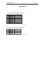
Appendix B
A. Connect A202 to RS232 (±12V Signal Level)
JS1
1
2
3
4
5
6
7
8
9
10
NC
Tx
Rx
NC
Gnd
NC
NC
NC
NC
NC
Out
In
Float
A202 Output to PC
A202 Input from PC
Inner Connect to Pin 6
Connect to Ground
Inner Connect to Pin 4
Inner Connect to Pin 8
Inner Connect to Pin 7
Float
Float
Note: JS1 uses fixed 1200 Baud Rate, 8 bit, 1 stop bit, no parity check,±12V Signal.
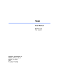
B. Connect A202 to UART (+5V Signal Level)
JP5
1 Powe
r
2 Rx
3 Tx
4 Powe
r
+5VDC out
In
Out
A202 Input from PC
A202 Output to PC
Ground
Note: JJP5 uses fixed 1200 Baud Rate, 8 bit, 1 stop bit, no parity check, +5V TTL Signal.
ICP Electronics Inc.
Page 21/35
ICP Electronics Inc.
Page 22/35
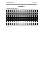
Appendix C
LCD-Module-supported ASCII codes
!
“
#
$
%
&
‘
(
)
*
+
,
.
/
0x20 0x21 0x22 0x23 0x24 0x25 0x26 0x27 0x28 0x29 0x2A 0x2B 0x2C 0x2D 0x2E 0x2F
0
1
2
3
4
5
6
7
8
9
:
;
<
=
>
?
0x30 0x31 0x32 0x33 0x34 0x35 0x36 0x37 0x38 0x39 0x3A 0x3B 0x3C 0x3D 0x3E 0x3F
@
A
B
C
D
E
F
G
H
I
J
K
L
M
N
O
0x40 0x41 0x42 0x43 0x44 0x45 0x46 0x47 0x48 0x49 0x4A 0x4B 0x4C 0x4D 0x4E 0x4F
P
Q
R
S
T
U
V
W
X
Y
Z
[
¥
]
^
_
0x50 0x51 0x52 0x53 0x54 0x55 0x56 0x57 0x58 0x59 0x5A 0x5B 0x5C 0x5D 0x5E 0x5F
`
a
b
c
d
e
f
g
h
i
j
k
l
m
n
o
0x60 0x61 0x62 0x63 0x64 0x65 0x66 0x67 0x68 0x69 0x6A 0x6B 0x6C 0x6D 0x6E 0x6F
p
q
r
s
t
u
v
w
x
y
z
{
|
}
→
←
0x70 0x71 0x72 0x73 0x74 0x75 0x76 0x77 0x78 0x79 0x7A 0x7B 0x7C 0x7D 0x7E 0x7F
**ASCII codes over the 0x80 are reserved for special symbols, please contact your sales representatives
for details.
ICP Electronics Inc.
Page 23/35
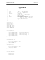
Appendix D
/*
*
*
*
*
*
*
*
*
*
*
*
*/
Title
Editor
Compilier
: A202.c --- A202 Demo program
: Davis Wang in ICP Electronic
: TCC Ver2.01
Use “TCC A202.c” to Compile A202.c
: DOS 6.22 or Above
: Use “C:\A202 String0 String1”
where String0 will display on LCD line 0
String1 will display on LCD line 1
e.g. C:\A202 ICP Electronic
OS
Execute
#include <dos.h>
#include <stdio.h>
#include <conio.h>
#define COM1 0x3f8
#define COM2 0x2f8
#define IOBASE COM1
void InitUART(void){
outport(IOBASE+3,
outport(IOBASE+0,
outport(IOBASE+1,
outport(IOBASE+3,
0x80);
0x60);
0x00);
0x03);
/* Line Control Register */
/* Divisor Latch Low
*/
/* Divisor Latch High
*/
}
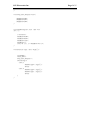
void SendByte(char ch){
while(!(inport(IOBASE+5) & 0x20));
outport(IOBASE, ch);
}
char GetByte(void){
while(!(inport(IOBASE+5) & 0x01));
return inport(IOBASE);
}
void Clear_LCD(void){
SendByte(0x4D);
SendByte(0x0D);
ICP Electronics Inc.
}
void Stop_Auto_Display(void){
SendByte(0x4D);
SendByte(0x7C);
SendByte(0x00);
}
void SendString(int line, char *s){
int i,j;
i=strlen(s);
SendByte(0x4D);
SendByte(0x0C);
SendByte(line);
SendByte(i);
for(j=0; j<i; j++)SendByte(*(s+j));
}
void main(int argc, char *argv[]){
InitUART();
Clear_LCD();
Stop_Auto_Display();
switch(argc){
case 2:
SendString(0, argv[1]);
break;
case 3:
SendString(0, argv[1]);
SendString(1, argv[2]);
break;
}
}
Page 24/35
ICP Electronics Inc.
/*
*
*
*
*
*
*
*
*
*
*
*
*/
Page 25/35
Title
: A202.c Demo program
Editor
: Davis Wang in ICP Electronic
Compilier : TCC Ver2.01
Use "TCC A202.C" to Compile A202.C
OS
: DOS 6.22 or Above
Execute : USE "C:\A202"
e.g. C:\A202
Result
: press any key on A202, and will see key status reflect on
PC monitor
#include <dos.h>
#include <stdio.h>
#include <conio.h>
#define COM1 0x3f8
#define COM2 0x2f8
#define IOBASE COM1
void InitUART(void){
outport(IOBASE+3,
outport(IOBASE+0,
outport(IOBASE+1,
outport(IOBASE+3,
0x80);
0x60);
0x00);
0x03);
/* Line Control Register */
/* Divisor Latch Low
*/
/* Divisor Latch High
*/
}
void SendByte(char ch){
while(!(inport(IOBASE+5) & 0x20));
outport(IOBASE, ch);
}
unsigned char Rs232Available(void){
return inport(IOBASE+5)&0x01;
}
char GetByte(void){
while(!(inport(IOBASE+5) & 0x01));
return inport(IOBASE);
}
ICP Electronics Inc.
void SendString(int line, char *s){
int i,j;
i=strlen(s);
SendByte(0x4D);
SendByte(0x0C);
SendByte(line);
SendByte(i);
for(j=0; j<i; j++)SendByte(*(s+j));
}
void Read_A202(void){
unsigned char Data1;
unsigned char Data2;
if(GetByte()!=0x53)return; /* A202 Leading Byte */
switch(GetByte()){
case 0x01: /* Report ID */
Data1=GetByte();
Data2=GetByte();
printf("Board ID is 0x%04X\n", (Data1<<8)|Data2);
break;
case 0x05: /* Report Key Status */
Data1=GetByte(); /* Data Byte 1 */
Data2=GetByte(); /* Data Byte 2 */
switch(Data2&0x1F){
case 0x00:printf("Key Released\n"); break;
case 0x01:printf("ESC Pressed\n"); break;
case 0x02:printf("UP
Pressed\n"); break;
case 0x04:printf("Enter Pressed\n"); break;
case 0x08:printf("Down Pressed\n"); break;
case 0x10:printf("Fn
Pressed\n"); break;
}
break;
}
}
void GetID(void){
SendByte(0x4D);
SendByte(0x00);
}
void main(void){
InitUART();
GetID();
while(!kbhit()){
if(Rs232Available())Read_A202();
}
}
Page 26/35
ICP Electronics Inc.
/*
*
*
*
*
*
*
*
*/
Page 27/35
Title
: MYIP.C Demo program
Editor
: Davis Wang in ICP Electronic
Compilier : TCC Ver2.01
Use "TCC MYIP.C" to Compile MYIP.C
OS
: DOS 6.22 or Above
#include <dos.h>
#include <stdio.h>
#include <conio.h>
#define COM1 0x3f8
#define COM2 0x2f8
#define IOBASE COM1
char
char
char
char
char
char
Quit=0;
data;
pos=0;
A[]={0, 1, 2, 4, 5, 6, 8, 9, 10, 12, 13, 14};
I[]={'1', '2', '7', '0', '0', '0', '0', '0', '0', '0', '0', '1'};
i, j;
void InitUART(void){
outport(IOBASE+3,
outport(IOBASE+0,
outport(IOBASE+1,
outport(IOBASE+3,
0x80);
0x60);
0x00);
0x03);
/* Line Control Register */
/* Divisor Latch Low
*/
/* Divisor Latch High
*/
}
void SendByte(char ch){
while(!(inport(IOBASE+5) & 0x20));
outport(IOBASE, ch);
}
char GetByte(void){
while(!(inport(IOBASE+5) & 0x01));
return inport(IOBASE);
}
ICP Electronics Inc.
unsigned char Rs232Avail(void){
return inport(IOBASE+5)&0x01;
}
void Clear_LCD(void){
SendByte(0x4D);
SendByte(0x0D);
}
void Stop_Auto_Display(void){
SendByte(0x4D);
SendByte(0x7C);
SendByte(0x00);
}
void SendString(int line, char *s){
int i,j;
i=strlen(s);
SendByte(0x4D);
SendByte(0x0C);
SendByte(line);
SendByte(i);
for(j=0; j<i; j++)SendByte(*(s+j));
}
void cursor_goto(unsigned char x, unsigned char y){
SendByte(0x4D);
SendByte(0x54);
SendByte(x);
SendByte(y);
}
void cursor_on(void){
SendByte(0x4D);
SendByte(0x9B);
SendByte(0x01);
}
void cursor_off(void){
SendByte(0x4D);
SendByte(0x9B);
SendByte(0x00);
}
void blink_on(void){
Page 28/35
ICP Electronics Inc.
SendByte(0x4D);
SendByte(0x9C);
SendByte(0x01);
}
void blink_off(void){
SendByte(0x4D);
SendByte(0x9C);
SendByte(0x00);
}
void print_string(char *s){
int i, count;
count=strlen(s);
SendByte(0x4D);
SendByte(0x9D);
for(i=0; i<count; i++)SendByte(*(s+i));
SendByte(0x00);
}
void print_char(char ch){
SendByte(0x4D);
SendByte(0x9D);
SendByte(ch);
SendByte(0x00);
}
void print_myip_template(void){
print_string("MY IP ADDRESS :\n");
for(j=0; j<3; j++){
for(i=j*3; i<(j*3+3); i++)print_char(I[i]); print_char(':');
}
for(i=9; i<12; i++)print_char(I[i]);
}
void main(void){
InitUART();
Clear_LCD();
Stop_Auto_Display();
print_myip_template();
cursor_goto(0, 1);
cursor_on();
blink_on();
while(!kbhit()&&!Quit){
if(Rs232Avail()){
Page 29/35
ICP Electronics Inc.
if(GetByte()==0x53){
switch(GetByte()){
case 0x05: /* Report Button Status */
data=GetByte(); /* skip data byte 0 */
data=GetByte(); /*
data byte 1 */
switch(data){
case 0x00:
/* Key_Released */
break;
case 0x01:
/* ESC_Key */
Clear_LCD();
print_string(" Good BYE !!");
cursor_off();
blink_off();
Quit=1;
break;
case 0x02:
/* Up_Key */
I[pos]=I[pos]+1;
if(I[pos]>'9')I[pos]='0';
print_char(I[pos]);
cursor_goto(A[pos], 1);
break;
case 0x04:
/* Enter_Key */
pos=pos+1;
if(pos>=12)pos=0;
cursor_goto(A[pos], 1);
break;
case 0x08:
/* Down_Key */
I[pos]=I[pos]-1;
if(I[pos]<'0')I[pos]='9';
print_char(I[pos]);
cursor_goto(A[pos], 1);
break;
case 0x10:
/* Fn_Key */
break;
}
break;
}
}
}
}
printf("My IP Address is %3d:%3d:%3d:%3d\n",
(I[0]-'0')*100+(I[1]-'0')*10+(I[2]-'0'),
(I[3]-'0')*100+(I[4]-'0')*10+(I[5]-'0'),
(I[6]-'0')*100+(I[7]-'0')*10+(I[8]-'0'),
(I[9]-'0')*100+(I[10]-'0')*10+(I[11]-'0'));
}
Page 30/35
ICP Electronics Inc.
/*
*
*
*
*
*
*
*
*
*
*
*
*/
Title
: A202.C Demo Program
Editor
: Davis Wang in ICP Electronic
Compilier : gcc
use "gcc -o A202 A202.c" to compile A202.C
OS
: Linux
Execute : USE "[..]$A202 String0 String1" as root
Where String0 will display on LCD line0
String1 will display on LCD line1
e.g. [root@localhost davis]$ ./A202 ICP Electronic
#include
#include
#include
#include
#include
<stdio.h>
<sys/ioctl.h>
<fcntl.h>
<termios.h>
<stdlib.h>
struct termios tio;
int fd;
void InitUART(void){
if((fd=open("/dev/ttyS0", O_RDWR|O_NDELAY|O_NOCTTY))<0){
printf("Could not open Serial Port\n");
exit(1);
}
tio.c_cflag
=B1200|CS8|CREAD|CLOCAL;
tio.c_cc[VTIME] =0;
tio.c_cc[VMIN]
=0;
tcflush(fd, TCIFLUSH);
tcsetattr(fd, TCSANOW, &tio);
fcntl(fd, F_SETFL, FNDELAY);
}
void Clear_LCD(void){
char s[]={0x4D, 0x0D};
write(fd, s, 2);
}
void Stop_Auto_Display(void){
char s[]={0x4D, 0x7C, 0x00};
write(fd, s, 3);
}
Page 31/35
ICP Electronics Inc.
void SendString(int line, char *s){
unsigned char c[]={0x4D, 0x0C, 0x00, 0x00};
c[2]=line;
c[3]=strlen(s);
write(fd, c, 4);
write(fd, s, strlen(s));
}
int main(int argc, char *argv[]){
InitUART();
Clear_LCD();
Stop_Auto_Display();
switch(argc){
case 2:
SendString(0, argv[1]);
break;
case 3:
SendString(0, argv[1]);
SendString(1, argv[2]);
break;
}
close(fd);
}
Page 32/35
ICP Electronics Inc.
/*
*
*
*
*
*
*
*
*
*
*
*/
Page 33/35
Title
: WDT.c Demo program
Editor
: Davis Wang in ICP Electronic
Compilier : TCC Ver2.01
Use "TCC WDT.C" to Compile WDT.C
OS
: DOS 6.22 or Above
Execute : USE "C:\WDT <time>"
where <time> is the time that WDT will start to count down
e.g. C:\wdt 10 --> Setup WDT Timer=10sec and start
#include <dos.h>
#include <stdio.h>
#include <conio.h>
#define COM1 0x3f8
#define COM2 0x2f8
#define IOBASE COM1
void InitUART(void){
outport(IOBASE+3,
outport(IOBASE+0,
outport(IOBASE+1,
outport(IOBASE+3,
0x80);
0x60);
0x00);
0x03);
/* Line Control Register */
/* Divisor Latch Low
*/
/* Divisor Latch High
*/
}
void SendByte(char ch){
while(!(inport(IOBASE+5) & 0x20));
outport(IOBASE, ch);
}
unsigned char GetByte(void){
while(!(inport(IOBASE+5) & 0x01));
return inport(IOBASE);
}
ICP Electronics Inc.
void Turn_On_WDT(void){
SendByte(0x4D);
SendByte(0x8E);
SendByte(0x01);
}
void Turn_Off_WDT(void){
SendByte(0x4D);
SendByte(0x8E);
SendByte(0x00);
}
void Clear_WDT(void){
SendByte(0x4D);
SendByte(0x91);
}
unsigned int Get_WDT_Timer(void){
unsigned char HiByte, LoByte;
SendByte(0x4D);
SendByte(0x8C);
if(GetByte()!=0x53)return 0xFFFF;
if(GetByte()!=0x8D)return 0xFFFF;
HiByte=GetByte();
LoByte=GetByte();
return (HiByte<<8)|LoByte;
}
void Set_WDT_Timer(unsigned int time){
unsigned char HiByte, LoByte;
HiByte=(time&0xFF00)>>8;
LoByte=time&0x00FF;
SendByte(0x4D);
SendByte(0x8B);
SendByte(HiByte);
SendByte(LoByte);
}
Page 34/35
ICP Electronics Inc.
void Do_My_Work(void){
unsigned int i=1000;
while(i--);
}
void main(int argc, char *argv[]){
unsigned int time;
InitUART();
switch(argc){
case 1:
printf("Use 'C:\WDT <time>' to setup WDT\n");
exit(1);
break;
case 2:
time=atoi(argv[1]);
if(Get_WDT_Timer()!=time)Set_WDT_Timer(time);
Turn_On_WDT();
break;
}
while(!kbhit()){
Do_My_Work();
Clear_WDT();
}
Turn_Off_WDT();
}
Page 35/35