1
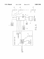
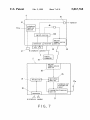
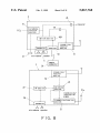
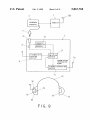
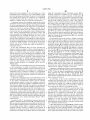
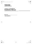
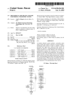
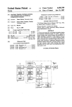
USOO5867768A
Ulllted States Patent [19]
[11] Patent Number:
Onda
[45]
[54]
SIMULTANEOUS MULTIDIRECTIONAL
5,404,577
5,438,702
5,586,176
_
[57]
[51]
[52]
[58]
Jackson ......... ..
.. 455/575
Peck ...................................... .. 455/568
ABSTRACT
A communication apparatus includes a plurality of
transmitter-receivers operatively coupled together so that
they are simultaneously communicatable over-the-air With
one another by Way of an interexchange repeater module,
Foreign Application Priority Data
[JP]
[JP]
4/1995 Zuckerman et a1. .................... .. 455/66
8/1995
12/1996
Attorney, Agent, or Firm—Morgan & Finnegan, LLP
[21] Appl- N05 711,550
[22] Filed:
Sep_ 10, 1996
Sep.13,1995
Jun. 12, 1996
Feb. 2, 1999
Primary Examiner_w?lis R_ Wolfe
_
[73] Ass1gnee: Baldwin-Japan, Ltd., Tokyo, Japan
[30]
Date of Patent:
COMMUNICATION APPARATUS
[75] Inventor: Takeo Onda, Fujimi, Japan
5,867,768
Int. Cl.6 ..................................................... .. H04B 1/38
US. Cl. ............................ .. 455/66; 455/575; 455/90;
455/568
Field of Search ................................ .. 455/66, 88, 90,
wherein 0n? of Such trtnsmitter'rectivers Comes With a
dlsplay devlce for Provldmg lnfermanon to th‘? user’ 219d a
telephone connector for connecting the transmitter-receiver
to the public telephone communication network. A sound
shielded headset is employed in the transmitter-receiver.
This headset includes an audio input/output section With a
microphonea Speakers and the likea and a transmitter/receiver
455/463, 500, 503, 526, 575, 568, 507,
function section for executing signal processing tasks
517, 351
required for communications. Upon reception of a telephone
signal, the transmitter-receiver is connected to the telephone
[56]
Japan .................................. .. 7-259502
Japan .................................. .. 8-172935
References Cited
connector by means of a cable-Wiring, optical coupling or
radio-Wave coupling scheme providing voice communica
U'S' PATENT DOCUMENTS
tions With the outside parties. In case Where the telephone
3,845,389 10/1974 Phillips et a1. ........................ .. 455/568
4,357,711 11/1982 Drefko et a1,
__ 455/575
5,113,428 5/1992 Fitzgerald ....... ..
455/568
5,119,505
6/1992 Tisseront et a1. .
Connector is 9(11111111991 With a known telephone Set, voice
communications Will be available by entry of phone num
bers over either external public lines or extension lines.
455/568
5,359,647 10/1994 Regen et a1. .......................... .. 455/568
21 Claims, 11 Drawing Sheets
7
drsplay
device
/\/ \|\
l. ___________________ _.
_
.
|- external srqnal
Input
_l
i
report
IA,
acknowledgemen r
i \
_
_
-
2‘
I
.
—l——-———>
:
}?:l:c0mmun|cat|un1|_)
?gmjegtpr
|
ev‘ce
!I
operatlon
.
section
'
li
6
8
|
|
-
.
I
I
|
I telephone set
l
\]\
BGM ——————>i
telephone
! 5
repeater
10
22
k ey
power <__l
suppl)!
14
'
\1
o
~
3\
\I\
.
_____________________ _.l
2n
battery charge
station
2/
U.S. Patent
Feb. 2, 1999
Sheet 1 0f 11
$7511...
W
7
5,867,768
?
53mg:
@>320
:23
If;vI.
2:2;
2
:32.
F..|,IL w_
2_35m2;.2;3 J
m2 538
"
2:3;:
_
_
_
_
_
__
22222:5
_
_
m
_
m
c
_
w
2:52
_2_
.29:25aE.
_
03m3_2 8
U.S. Patent
Feb. 2, 1999
Sheet 2 0f 11
F - - _ -
7
1
: disp | ay /
I device '
——1——'
l1
\
external
external
5,867,768
‘PPM
i nput
-
s I 9"‘!I
5mm, |
:
detector
' ‘
control ler
/
/
13
password
i nput
'
operat i on
section
external
i nt|>ut
se
ect signa I
key
10
\
12a
14
transmitter/receiver
section
repeater
1/
\
i2
FIG.2
U.S. Patent
Feb. 2, 1999
4
Sheet 3 0f 11
5,867,768
1
45
external
\
input
41
12a
46
_—§1 repeater
-lA
telephone
'FEl.
function
section
l/L
a
c
\
St
‘
42a
f1
connector
I
T
A: Z:
47
J;::]microphone
8
speaker
24
z//
/fi
connector
27
connection
detector
\\\
25
22
‘\“\\\\_ AFsection
sw'tch'ng
seétioa
21a
transmission/
interruption
signal
26
\\\\\
transmitter/receiver
connector
section
microphone speaker
FIG.3
I
21
U.S. Patent
Feb. 2, 1999
Sheet 4 0f 11
5,867,768
72
n
\
indicator lamp
device
1
device
2
73
device
8
/
device
A
7-1
_
repeater
external
input
signal
FIG.4
/
I
telephone
U.S. Patent
Feb. 2, 1999
Sheet 5 0f 11
5,867,768
Q56
23
2
_ _
_
_
_
_ _
_
_|
switching
'
7/
/‘r_|Jl
section
Il
: b
2
(be: blx Ago
"?g-"c
22 xx AF sect ion —/\——
mm
25
transmission
operation
transmission
interrupt
.
26
i;
\
\
transmitter/race i ver
connector
sect ion
95
microphone speaker
FIG, 5
/2‘
21a
U.S. Patent
Feb. 2, 1999
Sheet 7 of 11
\1
5,867,768
45
M
EH» repeater
A6 \FL
telephone
TEL
function
U
section
A A
switch section
2
optical
connector
47
communication
SENIOR
receiver
Pmicrophone
a; aspeaker
so
49
5
2\ 29/
remoted
comman er
optical
communication
section
28/
25
22 w
.
\ AF sect ion
switching
Section
21a
transmission/
interruption
signa I
26
\
transmitter/receiver
section
connector
I
iA
/
microphone speaker
FIG.7
2‘
U.S. Patent
Feb. 2, 1999
Sheet 8 0f 11
41
\|:|——>repeater
46 \r'l
telephone
TEL
5,867,768
funct ion
section
U
swi tch sect ion
/
42A
transmitter/
T
receiver
connector
I
receiver
L
sect ion
\
A; A
\
47 Fmicrophone\speaker
50
5t
5
2
\ 29/
remoted
common er
transmi
tter/
receiver
T
/ sect ion
52
25
22 \
.
\ AF sect ion
switching
Sect ion
21a
transmission/
interruption
s‘ na
26\
‘9
transmitter/receiver
\
sect ion
connector
microphone speaker
FlG.8
/
21
U.S. Patent
Feb. 2, 1999
Sheet 9 0f 11
4
5,867,768
1\
telephone
12a
repeater
connector
6
23
2
24
/
/
/
connector
27
-connection
\\\
detector
25
‘(
3]
l//,///
transmitter/
switching
receiver
section
///lsection
216
transmission/
interruption
signal
transmitter/receiver
section
/
21
62
30
64
22
63
60
FIG.9
61
U.S. Patent
Feb. 2, 1999
Sheet 10 0f 11
_____1
5,867,768
: display I/
I
11
vice
'
- - 7 - -'
\
externa l
/
input
: connector :
1 device
input
detector
' telephone '
/13
password
signal
1
7
control Ier
|
‘ ' ‘ ' T—
operat i on
section
4
external
input
select s i gna |
key
\
10
<
14
/
/15
dist r i butor/mixer
transmi tter/rece i ver
section
repeater
\
1/
\
12a
Y/
U.S. Patent
Feb. 2, 1999
Sheet 11 0f 11
Y \ i/21
1 \
repeater
Power
supply
5,867,768
\I\
<_____
.
2n
battery charge
station
/,
FlG.11
PRIOR ART
5,867,768
1
2
SIMULTANEOUS MULTIDIRECTIONAL
COMMUNICATION APPARATUS
so-called “sound-insulated” transmitter-receivers for use in
Working under noisy conditions, successful results are only
be achieved by employing Workers’ case-by-case
BACKGROUND OF THE INVENTION
procedures, Which expect a Worker Who received a telephone
call to i) use a selected telephone line being exclusively
connected to the repeater, ii) catch the call using a
1. Field of the Invention
This invention relates to telecommunication apparatus
transmitter-receiver that is presently in the out-of-busy state,
adaptable for use in noisy environments including furnace
factories, sheet-metal or Web production Workplaces such as
press-Working, airplane setup/maintenance Works in the
airport, print/press factories, and the like, and, more par
10
ticularly to voice communications apparatus capable of
attaining successful transmission of voice messages and
factory in order to hook up the telephone handset; it may
alternatively occur that s/he has to go out of the factory to
use one of remotely located telephones in calm areas outside
phone-calls under high noisy conditions.
2. Description of the Related Art
or iii) ask his or her associate to separately connect With the
calle. It Will also occur that the called party must put his/her
upper body or head into a sound-shielded box Within the
the factory. The prior art sound-insulated transmitter
receivers are unable to insure direct telecommunications
15
plary apparatus for such sound-insulated transmitter
With external telephones as linked by Way of the public
telecommunication netWorks; accordingly, it Will be inevi
table for Workers to interrupt their oWn Works until comple
tion of the present conversation betWeen the caller and the
called party over telephone, or to temporarily change the
receiver is shoWn in FIG. 11. In this apparatus a plurality of
Work to a different kind of one that may be done Without the
transmitter-receiver 2 (21, 22, . . . , 2n) are operatively
need of attendance of the calling or called Worker. In any
Way, this should result in a decrease in ef?ciency of Work
Conventionally, portable radiotelephones using a sound
shielded headset (sound-insulated transmitter-receiver) are
employed as the communication means betWeen Workers
under noisy conditions full of ambient noises. One exem
coupled over-the-air to one another using radio Waves by
Way of a repeater 1. Any audio messages sent form the
repeater 1 may be heard at all of the transmitter-receivers 2
providing simultaneous multidirectional communications. A
ability.
25
battery-charge station 3 charges the batteries of respective
transmitter-receivers.
Each transmitter-receiver 2 is provided With a headset of
excellent sound insulation, Which consists of a pad section,
a support member and others. This headset is of the head
inspection device (PQD) for inspection of printing machines
or a spray dampener (SD) experiences failures accidentally,
the resulting printing matter Will be expressly loWered in
quality causing the productivity to decrease signi?cantly. To
phone type containing therein a microphone, a speaker(s),
and a transmitter/receiver function section. Factory Workers
use such headphones by putting them on their heads to
enable simultaneous multidirectional conversations to be
Under high noisy circumstances it is required that, upon
occurrence of failures in Working machines, such informa
tion be rapidly informed to Workers so that necessary
recovery/repairing procedures can be applied at the earliest
convenience. One example is that When a paper quality
eliminate such reduction in productivity, rapid handling for
35
carried out attaining required voice communications among
them. The microphone detects ear-bone vibrations upon
recovery is strictly required at any events.
It is therefore an object of the present invention to provide
a communications apparatus capable of retaining reliable
communicationability With outside parties in situ under
noisy circumstances by letting a repeater have a function of
transferring information identical to any external signal
inputs toWard all of the transmitter-receivers operatively
coupled thereWith in the apparatus.
occurrence of a voice message and convert it into a corre
sponding electrical signal.
In the case Where a telephone call is made in noisy
environments of relatively higher noise level, it Will possibly
happen that the microphone also picks up the ambient
sounds making it dif?cult for a Worker to hear his or her
It is another object of the invention to provide a voice
aimed voice messages due to masking effects of background
communications apparatus capable of alloWing Workers to
noises. Under such conditions, it is no longer easy for a
Worker to accurately transfer his or her voice messages; this
necessitates a called party to ansWer back the caller for
con?rmation, Wasting time and effort With the result in an
45
interconnectivity betWeen sound-insulated transmitter/
receivers and telephone connector devices.
It is yet another object of the invention to provide a voice
communications apparatus capable of attaining conversa
tions over public or extension telecommunication lines by
entering telephone numbers on part of a telephone operation
increase in conversation time While reducing ef?ciency. One
prior knoWn approach for avoiding the problems is to install
telephone booths of a sealed environment; another approach
is to put each telephone set at a location of relatively loW
panel of a telephone connector device to ensure that Workers
can call a target party under noisy in-situ conditions Without
noise levels. Unfortunately, such approaches cannot alWays
offer intended advantages on occasions Where there are no
such spaces Wide enough to permit location of the telephone
55
booth, or on occasions Where such ideally loW-noise places
are not available Within the factory. If this is the case, it is
a must to put the telephones at noisy locations, Which lacks
the ability to provide any satis?able conditions for Workers
to telecommunicate With each other.
having to move far from their original Working places during
operations.
It is a still another object of the invention to provide voice
communications apparatus capable of immediate start of
conversations in situ over telephone upon reception of a
telephone call While providing as needed the possibility of
simultaneous multidirectional transmission/reception of oral
Incidentally, there has been long desired a speci?c type of
telephone handset suitably adaptable for use in voice com
messages among a plurality of transmitter-receiver users
concerned, to thereby suppress or eliminate degradation of
munications in noisy environments namely, the one that can
ef?ciency otherWise occurring When a Worker must move far
be directly installed under high noisy conditions and also
attain clear conversations Without having to be interfered
With mixture of background noises With no interruptions in
intended telecommunications. On the other hand, in the
call over telecommunication channels under noisy in-situ
conditions by providing an extra function for enabling
65
from his or her Working place for telephone calls.
It is a further object of the invention to provide a tele
communications apparatus capable of retaining security for
5,867,768
4
3
covert conversations While preventing leakage of informa
tion content to other transmitter-receivers by forcing upon
means, Wherein informing of telephone reception or
receipt of a telephone call a communication function to be
interrupted betWeen the transmitter-receiver of a called party
using sounds and/or visual indications.
abnormality Warning in the machinery equipment is done
(7) The repeater comes With a communication section for
enabling the oWner of a telephone connected With the
telephone line to telecommunicate With one or a plurality
of transmitter-receiver users by Way of the repeater.
(8) Each transmitter-receiver includes a means for causing
the communication functions to break off betWeen it and
other transmitter-receivers When connected to the tele
phone connector device, and a means for resetting the
and other transmitter-receivers, and also capable of main
taining mutual communication functions among the other
transmitter-receivers to alloW these transmitter-receivers to
continuously remain active in telecommunications among
them thus eliminating any possible interruptions in execu
tion of Works required.
It is a yet further object of the invention to provide a
communication functions therebetWeen by disconnecting
telecommunications apparatus capable of alloWing tele
the connection With the telephone connector.
(9) The repeater has a communication retaining function of
enabling, When one transmitter-receiver is coupled to the
telephone connector, communications among the other
transmitter-receivers.
(10) The display means includes an indication lamp that
phone responses and call-up of a target party to be smoothly
carried out by use of a speci?c kind of sound and/or visual
indication scheme to inform the target person of the presence
of a telephone call.
SUMMARY OF THE INVENTION
turns on for acknoWledgement upon reception of a tele
The present invention has been made to avoid the afore
phone call or of Warning signals in the machinery equip
said problems and to achieve the foregoing objects.
ment.
A communications apparatus of the invention has a
repeater, and a plurality of transmitter-receiver operatively
coupled to be simultaneously radiocommunicatable With
one another multidirectionally by Way of the repeater,
The sound-shielded headset as preferably used in the
communications apparatus is arranged as folloWs:
(1) The headset has a sound-shielded structure, and com
25
Wherein a sound-shielded headset is adapted in one or more
transmitter-receivers, including an audio input/output (I/O)
audio I/O section including a microphone and speaker,
section With a microphone and speaker, and a communica
tion means containing therein a transmitter/receiver function
and a transmitter-receiver function section for perform
ing signal processings required for communications,
section for execution of signal processing required for
Wherein voice communications are available by caus
communications and being held at or near a human body for
ing the communication means to be operatively
coupled to the telephone connector by use of a tele
handheld use, featured by comprising an informing means
for providing necessary information to a user of a
phone cord-coupling unit, an optical transmit-and
transmitter-receiver operatively coupled to the repeater
receive scheme, or a radiocommunication scheme.
Which transmits information corresponding to an external
(2) The transmitter-receiver function section of the com
signal input to all the transmitter-receivers by Way of the
munication means includes a ?rst transmitter/receiver
informing means.
In accordance With the invention, due to the use of the
function section for processing signals With respect to
the audio I/O, and a second transmitter/receiver func
repeater With the function of transmitting information
indicative of an external signal input toWard all the
transmitter-receivers, it is possible even in high noisy envi
tion section for performing signal processings betWeen
it and the ?rst section and those betWeen the telephone
connector and the repeater, Wherein the ?rst section is
ronments to provide transmitter-receiver users With infor
in a attachment means attached to selected positions of
mation identical to the external signal input, such as notices,
a human body involving auditory sensible organs,
broadcast messages, background music, acknoWledgement,
Warning, or the like, thus enabling the Workability to be
enhanced in the communications apparatus.
The communications apparatus of the invention may
preferably be arranged as folloWs:
Whereas the second section is at or near the human body
45
for mobile use.
BRIEF DESCRIPTION OF THE DRAWINGS
(1) An external signal input is a telephone receipt signal, and
the repeater is responsive to such signal for causing the
informing means to inform all the transmitter-receivers of
the reception of a call.
(2) The external signal input may be a signal representative
of occurrence of abnormal operations, a Warning signal or
the like as in the machinery equipment used.
prises a communication means Which is held at or near
a human body for mobile use and Which comes With an
55
(3) The external signal input may alternatively be an audio
signal such as a human language, notices, broadcast
messages, background music, alike.
FIG. 1 is a draWing shoWing a con?guration of a voice
communications apparatus in accordance With a ?rst
embodiment of the invention.
FIG. 2 is a block diagram of the repeater.
FIG. 3 is an overall block diagram.
FIG. 4 is a diagram shoWing an arrangement of an
indicator lamp unit as one exemplary display device.
FIG. 5 is a block diagram shoWing an exemplary sWitch
unit for changeover betWeen a transmitter-receiver and a
telephone.
(4) A transmitter-receiver and its associated telephone con
nector device are coupled together by a cord coupling,
radio communication, or optical communication scheme.
(5) The informing means includes a means for sending forth
FIG. 6 is a diagram shoWing a con?guration of a second
embodiment of the invention.
sounds to all the transmitter-receivers While employing as
transmitter-receiver using an optical communication
an informing sound of telephone reception a speci?c kind
of sound identically distinct from other Warning signals
(6) The informing means includes a means for sending forth
sounds to all the transmitter-receivers and/or a display
FIG. 7 is a block diagram of a telephone connector and a
65
scheme.
FIG. 8 is a block diagram of a telephone connector device
and a transmitter-receiver using a radio transmit-and-receive
technique.
5,867,768
6
5
FIG. 9 is a apparatus con?guration diagram showing one
possible modi?cation of the second embodiment.
The telephone connector device 4 functions to connect the
public telephone line (TEL) to the repeater 1, and acts as
FIG. 10 is a block diagram of the repeater of a third
embodiment.
either a telephone set consisting of a knoWn telephone
FIG. 11 is a diagram shoWing a apparatus con?guration of
receiver as its handset. This device 4 also has a telephone
interconnection function that sends forth a telephone recep
tion signal upon reception of a call at a telephone set
handset 5 or a telephone set that utiliZes one transmitter
one prior art transmitter-receiver.
DETAILED DESCRIPTION OF THE
PREFERRED EMBODIMENTS
An arrangement of the invention Will be de?ned as
(external line) using public telecommunication netWorks
oWned by a telephone company or at a telephone set
10
folloWs. The terminology “sound shield” means loWering
of the telephone company’s public netWorks, and Which
connects it to either the telephone handset 5 or transmitter
receiver 2 of a target user—namely, the calling or called
party. The telephone connector 4 also comes With a cable 8
ambient noises to a degree that there are no substantial
interferences With voice communications. The “headset” is
constituted from a pair of earpads or ear-muff entirely
covering the ear of the use—or alternatively, an earplug
(extension) using its oWn telephone netWork by Way of none
having a transmitter-receiver connection connector 6 as a
15
adapted to be inserted thereinto and a communication means
means for connecting it to the transmitter-receiver 2. The
connector 6 is engageable by a hook With the main body of
device 4; While the telephone is in use, this connector is
attached to and held at or near a human body. The commu
nication means includes an audio input/output (I/O) section
having a microphone and speaker, and a transmitter/receiver
taken out of the hook to be connected to transmitter-receiver
2 enabling voice communications With a target person.
As shoWn in FIG. 2, the repeater 1 is constituted from an
function section for performing signal processing tasks as
required for voice communications.
external signal input detector 11, a transmitter/receiver (TX/
The illustrative embodiments are arranged such that a
RX) section 12, a controller 13, and a key section 14. The
repeater is added With external-input functions of receiving
detector 11 serves to detect an external input signal(s). When
several signals externally fed thereto, including telephone
detector 11 detects any external input signal, TX/RX 12
processes signals as to reporting and Warning tasks required
signals, equipment failure occurrence signals, voice mes
sages such as reports or acknowledgement, background
music (BGM) audio signals, or the like. For example, When
an external cable broadcasting program source is employed
25
for all of the transmitter-receivers 2 and then transmits
over-the-air the resulting signals from an antenna 12a, While
also performing display processings for Warning indication
to render the display device 7 operative. Repeater 1 has also
a function of selecting interconnection of external signal
as BGM, a cable broadcast receiver is tied to an external
signal input terminal. Note that the voice communications
apparatus of the invention is generally similar in basic
apparatus con?guration to the prior art apparatus shoWn in
FIG. 11. Hence, only distinguishing features of this inven
tion Will be described herein: Like reference characters
designate like parts or components, and a detailed explana
tion thereof Will be omitted.
FIG. 1 shoWs a apparatus con?guration of a ?rst embodi
inputs in response to key inputs and/or passWord inputs. To
achieve this function, a key signal and/or a passWord signal
may be input to controller 13. Some apparatus may be
employed to provide such external signal inputs: in POD, a
35
apparatus is employed to detect occurrence of printing
failure or malfunction; in SD, a apparatus is used to issue
Warning upon occurrence of interruption of Water feed,
shortage of dampening Water, or reduction of Water pressure.
ment of the invention. This embodiment enables at least one
of transmission and reception units (portable radiotelephone
Repeater 1 is arranged to indirectly detect such Warning by
or transmitter-receivers) 2 to be coupled by a cable to a
use of either an light or a radio transmission scheme;
telephone connector device 4 When used for telecommuni
cations. A repeater 1 is designed, in addition to its inherent
alternatively, a relay sWitch circuit is provided in each
device alloWing the repeater to be directly tied to such relay
interexchange and repeat functions, to perform external
signal input detection for selecting a speci?c external input
signals being received by the voice communications appa
sWitch circuit.
The external signal input detector 11 is responsive to a
select signal sent from the controller 13 for selection of a
45
certain external signal input corresponding to a key input
ratus in response to entry of keying input and/or of a
passWord. The repeater 1 is also responsive to a telephone
and/or a passWord input fed from controller 13, and extracts
from those external signal inputs a speci?c one that matches
With the voice communications apparatus, causing it to be
coupled thereto. More speci?cally, in order to protect the
reception signal from the telephone connector device 4
connected to the external signal inputs, for carrying out
voice message handling procedures as required to transmit a
speci?c audible sound that distinguishes from others a sound
for use in Warning or reporting. The repeater 1 informs all of
communications apparatus against accidental operational
the transmitter-receivers of such telephone reception by use
of the speci?c sound upon reception of a telephone call from
the outside, and simultaneously causes a display device 7 to
55
exclusively receiving appropriate “Welcome” external signal
perform visual indications for informing that a telephone
call is being presently received. Here, the speci?c sound
generation section and display device constitutes such
inputs With prede?ned speci?cations, and a lock-release
function for resetting the locking function. To attain these
informing device, Which is also capable of attaining inform
functions, a mechanical key is connected to a contact of a
sWitch, Whereas a circuit connected to an input terminal of
ing functions for Warning or reporting as to factory equip
the repeater (this terminal is for taking a signal externally
input thereto into the external signal input detector) is
ment concerned. To produce a signal indicative of Whether
the reception of external signal input is permissible or not,
an arrangement is additionally provided Which may be a key
section 14 consisting of a combination of mechanical
dataentry keys and sWitches, or of a combination of such
interruption or signi?cant decrease in performance due to
inbound of “strange” external signal inputs that are out of the
protocols as employed in the communications apparatus, the
external signal input detector 11 has a locking function for
selectively set in the connect or in the nonconnect state.
Another approach to attain the above functions is that a
65
mechanical key is designed to cooperate With passWord
mechanical keys and an operation section 10 for passWord
inputs While similarly setting the circuit in the connect or the
entry.
nonconnect state.
5,867,768
7
8
As shown in FIG. 3, the telephone connector 4 is gener
ally constituted from a telephone function section 41 for
enabling it to be used also as an ordinary telephone, a
changeover sWitch (St) 42 acting as a changeover means for
changing over the signal transmission line betWeen tele
during execution of their expected Works. Lamp unit 71 has
at the upper position thereof an array of telephone labels 72
With characters that indicate devices #1 to #4 and one
telephone as objects being monitored; unit 71 also has at its
loWer position an array of a corresponding number of lamps
73 as shoWn. Lamp unit 71 carries out light turn-on opera
tions under the control of controller 13 of repeater 1 in
accordance With an external signal input as detected by
phone 5 and transmitter-receivers 2, a hook 43 as an opera
tion means for operating sWitch 42, a cable 8 having a
transmitter-receiver connection connector 6 that is normally
hung on hook 43, and buffer sections 45, 46 for Waveshaping
respective signals, one of Which is inserted betWeen tele
phone function section 41 and repeater 1, and the other of
detector 11. Especially, regarding the device #1 to #4, lamp
unit 71 is arranged to inform Workers of occurrence of
device failures. Accordingly, Workers can ?gure out, by
visually checking the light turn-on position after hearing
Which is betWeen section 41 and transmitter-receivers 2 as
shoWn. The buffer 46 is connected to the telephone function
sounds, Which one of the devices #1 to #4 and the telephone
section 41 by Way of a ?xed contact a and a common contact
is presently subject to acknoWledgement, Warning or report.
c of the changeover sWitch St.
The sWitch 42 consists of a toggle sWitch mechanism With
15
the hook 43 being as its operation lever. As indicated by
solid line in FIG. 3, When the connector 6 is out of hook 43,
the common contact c of sWitch St is connected to one ?xed
contact a causing transmitter-receiver 2 to be operatively
coupled With telephone function section 41 of telephone
connector device 4 so that telecommunications are available.
When connector 6 is put on hook 43, the common contact c
is alternatively connected to the other ?xed contact b as
designated by broken line in FIG. 3 causing telephone
25
function section 41 to be operatively coupled to telephone
handset 5 alloWing device 4 being able to operate as an
ordinary telephone.
sWitch circuit an audio U0 is connected to common contact
Upon reception of a telephone call, once the connector 6
c throughAF section 22. Connector 23 is connected to ?xed
contact a through buffer 27. Contact b is connected to an I/O
terminal of TX/RX 21.
A second sWitch circuit is for changing over the operation
mode of transmitter-receiver 2 betWeen the transmit
is disconnected from the hook 43, the operation signal
(unlock signal) is supplied from the changeover sWitch 42 to
the telephone function section 41 through a signal transmis
sion line 42a. In response to this signal, a hold sWitch 47 is
rendered operative. The “hold” function is to hold the
telephone line active While a target person comes here after
being called up by a Worker Who ?rst responded to the
telephone call, even if connector 6 is returned to hook 43.
Telephone handset 5 and connector 48 constitute a telephone
voice I/ O section. Note that hold sWitch 47 is for temporarily
interrupting telecommunications, Which is similar to the
activation and interruption. This circuit has a pair of ?xed
35 contacts a, b connected to TX/RX 21, and a common contact
c coupled to ground. To let the transmission get started or
interrupt in responding to an input signal from sWitch Sh, the
TX/RX 21 is arranged as folloWs: it interrupts transmission
When the ?xed contact a is grounded (LoW: L signal) While
the ?xed contact b is open (High: H signal); it alloWs
hold function of knoWn telephones. The telephone function
section 41 has con?guration and functions of conventional
transmission to get started When contact a is at the H signal
While contact b is at the L signal. The audio U0 is connected
to TX/RX 21 in response to initiation of the transmission
telephones.
The transmitter-receiver 2 of FIG. 3 includes a TX/RX
section 21, an AF section 22 for amplifying a reception
One exemplary arrangement Will noW be discussed With
reference to FIG. 5, Which detects actual connection
betWeen transmitter-receiver 2 and telephone connector 4 to
sWitch from the transmitter-receiver to the telephone.
This example employs as its sWitching section a
changeover sWitch (Sh) 25 With a mechanical sWitch assem
bly. SWitch 25 sWitches from one ?xed contact b to the other
a in response to insertion of the connector 6 of telephone
connector device 4 into connector 23. When connector 6 is
out of connector 23, sWitch 25 automatically recovers at the
?xed contact b. SWitch 25 includes a tWo-circuit/tWo-contact
sWitch mechanism. A ?rst sWitch circuit changes over
betWeen the telephone and transmitter-receiver. In the ?rst
45
operation. During the transmission operation, an antenna
21a externally sends forth over-the-air corresponding elec
signal processed by TX/RX 21 and audio/voice signals input
tromagnetic Waves; this antenna may also catch radio Waves
from the microphone, a connector 23 for connection
from other transmitter-receivers so that it may function as a
betWeen transmitter-receiver 2 and telephone connector
device 4 by Way of cable 8, a connector connection detector
24 for detecting the actual connection betWeen transmitter
receiver 2 and telephone connector device 4 by Way of cable
8, a sWitching section 25 responsive to the signal from
detector 24 for changing over the line betWeen transmitter
receiver 2 and the telephone, and an audio I/O section Which
simultaneous multidirectional communicatable transmitter
inactive that is, recover or interrupt selectively. The recovery
of communication function is to let the transmission opera
tion get started in response to a transmission enable signal as
set 5 is picked up; after entry of a desired telephone number
receiver. Additionally, the changeover processor is not
exclusively limited to the sWitch Sh; it may alternatively be
a contactless sWitch knoWn as the electronic sWitch.
The voice communications apparatus operates as folloWs.
The telephone connector device 4 is normally sWitched to
the side of telephone handset 5 as the connector 6 is put on
includes a microphone, a speaker and a connector section 55 hook 43. When a telephone call is required over external
26. TX/RX 21 renders the communication function active or
public telecommunication lines or extensions thereof, hand
on the telephone operation panel, the telephone function
section 41 of device 4 is operative rendering it active for
telecommunications. Upon reception of a telephone call
sent from sWitching section 25; the interruption of commu
nication function is to cause the transmission to stop in
over either the public line or the extension, this is noticed
response to a transmission disenable signal. Additionally,
numeral “27” designates a buffer section similar in function
to that 46 of telephone connector device 4.
As shoWn in FIG. 4, the display device 7 may include an
indicator lamp unit 71. This unit may be located at a selected
from device 4 to repeater 1. When external signal input
detector 11 detects that the presently received calling is a
telephone call, repeater 1 causes a corresponding indicator
lamp to turn on emitting light, and simultaneously informs
position that facilitates Workers’ visual acknoWledgement
65
all of the transmitter-receivers 2 (21, 22, . . . , 2n of FIG. 1)
of such state by providing an informative sound thereto. A
5,867,768
9
10
person Who ?rst responded to the call makes use of the
transmitter/receiver function to try to acknowledge a target
using the transmitter-receiver. SWitching section 42A is
normally connected to handset 5; it is changed over by
person by speaking and calling up the person. In responding,
s/he (called party) inserts the connector 6 of telephone
by a target person Who is expected to respond to the caller.
manual operation of a remote controller or commander 29
headset to establish electrical connection therebetWeen.
Connection betWeen the telephone connector 4 and the
The remote commander 29 may have a transmitter including
therein an IR emission element: it emits a ?rst signal in
response to user’s manual operation such as depressing a
transmitter-receiver of the target person being called enables
key button. This ?rst signal travels over-the-air toWard a
connector device 4 into the connector of his or her oWn
receiver 50 including an IR sensor. This receiver is respon
his or her communications With the caller. At this time, the
communication function of the target person’s transmitter
receiver is forced to interrupt making it unable for all
persons but the called party (the remaining transmitter
receivers) to hear the conversation content. Simultaneously,
10
ing section 42A While causing optical communication sec
since mutual telecommunication functions remain still
active among the remaining transmitter-receivers, any voice
sive to receipt of the ?rst signal for rendering the sWitching
section operative so as to disconnect handset 5 from sWitch
15
tion 49 to be connected to telephone function section 41.
When an additive manual operation is done such as depress
ing the button of remote commander 29, it emits a second
communications are available betWeen any ones of the
signal for causing the sWitching section 42A to be sWitched
remaining transmitter-receivers Without any inconve
niences. After completion of the talking over phone betWeen
the caller and called party, s/he disconnects connector 6 from
the headset causing telephone connector device 4 to be in the
normal state shoWn in FIG. 1, in Which the transmitter
to the side of handset 5.
The transmitter-receiver 2 includes a TX/RX section 21,
receiver returns to its initial state Where it functions as a
transmitter-receiver.
In the ?rst embodiment there has been described the
apparatus Which is arranged to achieve acknoWledgement of
25
recipt of a telephone call by use of both visual indication of
light at an indicator lamp and acoustic sensation using
sounds; hoWever, it may alternatively be modi?ed so that
such acknoWledgement is accomplished by exclusive use of
a speci?c kind of sound, involving a characteristic sound
that enables Workers to audibly recogniZe reception of a
transmission interrupt signal is input from sWitching section
25, it interrupts any communication functions With respect
to other transmitter-receivers; When the transmission enable
signal is input, TX/RX 21 recovers the communication
telephone call, such as electronically synthesiZed call-up
voice. It is also possible to more reliably inform a target
person of such reception of a telephone call by use of a
?ashing light.
a sWitching section 25, an optical communication section 28,
and an audio I/O section. When the optical communication
section 28 receives optical emission from the optical com
munication section 49 in telephone connector device 4, the
sWitching section 25 then connects the audio I/O section to
optical communication section 28, and supplies a transmis
sion interrupt signal to TX/RX 21. When optical communi
cation section 28 receives information representative of the
fact that the telephone is cut off, sWitching section 25
provides TX/RX 21 With a transmission enable signal While
causing the audio 1/0 to be operatively coupled to TX/RX
21. The operation of TX/RX 21 is as folloWs: When the
35
Further, While the embodiment has been described based
on the arrangement in Which the telephone connector 4
functions. Note that an optical cable may alternatively be
used in the case Where transmitter-receiver 2 and telephone
connector 4 are optically coupled to each other.
comes With a single transmitter-receiver connector 6, such
A apparatus con?guration using the radiocommunication
device may alternatively be provided With a plurality of
transmitter-receiver connectors enabling a corresponding
scheme is shoWn in FIG. 8. This apparatus is similar to that
of FIG. 7 With the optical communication sections 28, 49
number of transmitter-receivers to remain connectable there
With. In this case, the telephone connector is increased in
being replaced With radio TX/RX sections 51, 52. More
impedance accordingly.
A apparatus con?guration of a second embodiment of the
invention is shoWn in FIG. 6. This embodiment employs one
of the optical communication scheme and the Wireless
communication scheme to alloW the telephone connector
device 4 to be operatively coupled to transmitter-receiver 2.
The illustrative apparatus of FIG. 6 is similar in arrangement
to that shoWn in FIG. 1 With the telephone cord for connec
tion betWeen the transmitter-receiver 2 and telephone con
nector device 4 being replaced by one of an optical com
munication using infrared (IR) light and Wireless
communication using radio frequency (RF), for example. A
apparatus con?guration using the optical scheme is shoWn in
45
a manner that the called party can use the phone namely,
responding and calling over telephone Without having to
come to the exact phone place or a nearby place, Which in
turn enhances the ef?ciency of handling the same.
An embodiment shoWn in FIG. 9 is such that part of the
communication means of the transmitter-receiver is held
near the headset. This embodiment is similar to the ?rst
55
embodiment in arrangement concerning the connection
betWeen the telephone connector and the transmitter
receiver. This embodiment features in that the audio I/O and
FIG. 7, Wherein like reference characters designate like parts
or components, and a detailed description thereof Will be
omitted herein.
As shoWn in FIG. 7, the telephone connector device 4 is
includes a telephone function section 41, a sWitching section
42A, an optical communication section 49, and an audio I/O
section. When telephone function section 41 is connected by
the sWitching section 42A to telephone handset 5, the
telephone function becomes available using handset 5;
speci?cally, this apparatus uses these TX/RXs 51, 52 to
attain Wireless communications betWeen TX/RX 2 and tele
phone connector device 4.
An advantage of the second embodiment is that the
useability and Workability can be further enhanced in such
Wireless TX/RX section of the communication means are
attached at or near the headset. An intended technical
signi?cance of such arrangement lies in that part of the
communication means is built in an earmuff, or incorporated
into a headband coupled thereto.
In FIG. 9 the headset has earmuffs 60, 61 coupled together
alternatively, When section 41 is connected to optical com
by a head band 62. One muff 60 contains therein a speaker
63, Whereas the other muff 61 includes a microphone 64.
The muff 61 With microphone 64 also contains an AF section
munication section 49, the telephone function is established
22 for signal-processings With respect to audio/voice inputs
65
5,867,768
11
12
from the microphone and audio/voice outputs of the speaker,
disconnects the connector 6 of the telephone terminal
and a Wireless TX/RX section 30 for causing signals to be
machine and connects it to his or her oWn transmitter
transmitted over-the-air to or received from transmitter
receiver. Under the condition, since this transmitter-receiver
receiver 2. Switching section 25 provides controls for oper
ating TX/RX 21 in accordance With the actual connection
comes With the covert function, it Will no longer occur that
the conversation content over telephone is transmitted to
state betWeen transmitter-receiver 2 and telephone connector
other transmitter-receivers. If the simultaneous multidirec
tional communications are required here, the operation sec
tion 10 of repeater 1 is operated to change over to the
“simultaneous multidirectional communications” mode,
Whereby the telephone line is connected to the other
device 4, or for temporarily interrupting transmission opera
tions. When transmitter-receiver 2 is cable-connected by
Way of connector 6 to device 4, the resulting connection
state is detected by detector 24. Upon receipt of a connection
detection signal from detector 24, sWithing section 25 gen
transmitter-receivers providing communicationability. Note
hoWever that the transmitter-receiver being presently con
nected by the connector is still effective in the covert
erates and issues a transmission enable signal Which is fed
to TX/RX 21. Upon receipt of a transmission disenable
signal from sWitching section 25, TX/RX 21 attempts to
interrupt the transmission operation toWard repeater 1. With
function; therefore, such transmitter-receiver cannot join the
15
this operation, the so-called secret speaking or “covert”
function is available that is, a selected person Who oWns
transmitter-receiver 2 operatively coupled to telephone con
gone aWay. This may be eliminated by preventing the
connector from being hung on the hook and by letting it be
free after disconnection from the transmitter-receiver,
thereby enabling this transmitter-receiver to join the simul
taneous multidirectional communications. After completion
of the simultaneous multidirectional communications, the
nector device 4 can exclusively be alloWed to carry out
conversations over phone. When the connection betWeen
transmitter-receiver 2 and device 4 is released, the resultant
state is detected by detector 24. Processor 25 supplies a
transmission enable signal to TX/RX 21. In response to this
signal, TX/RX 21 initiates transmission operations. Due to
this, the TX/RX that has been used for telephone is noW set
in a mode that enables telecommunications With any one(s)
of the other transmitter-receivers.
simultaneous multidirectional communications. On the
other hand, When the connector is out of the transmitter
receiver and then is put on hook 43, the telephone call is
connector is put on the hook to turn off the telephone.
25
In this embodiment, selecting of the simultaneous multi
directional communication functions may enable the oWner
of a telephone linked to the telephone lines to make con
versations by Way of repeater 1 With one or a plurality of
Note that a transmitter/receiver function section of the
communication means includes a ?rst transmitter/receiver
transmitter-receiver users.
function unit consisting of a TX/RX 30, and a second
While the invention is With the informing device added to
transmitter/receiver function unit consisting of a TX/RX 21,
the repeater and the telephone connector, the meaning of the
language “added” covers any possible arrangements Where
the informing device and telephone connector are externally
coupled to the repeater that is, an arrangement Wherein each
of them stands independent of others in hardWare structure,
a connector connection detector 24, a changeover section 24
and a TX/RX 31. The ?rst unit is arranged at a component
being attached to the auditory parts of human body, such as
the earmuff, for example. The second unit is held at a
selected position near the human body excluding the acous
tic sensible part thereof; for example, it is put in a pocket, or
35
and an arrangement in Which the informing device and
telephone connector are built in the inside of the repeater to
provide an integral structure.
The present may also encompass in scope an arrangement
attached to a band.
This embodiment is generally similar in operation to the
?rst embodiment, except that the communication means is
held near the headset and that communications betWeen this
Wherein no telephone connector is additionally coupled to
the repeater While alloWing a sound-shielded headset to be
communication means and the transmitter-receiver is per
connected to the telephone connector providing the use of an
formed using Wireless telecommunication schemes using
ordinary telephone set therefor.
radio Waves.
An apparatus con?guration of a third embodiment of the
invention is shoWn in FIG. 10. This is aimed at
simultaneous multidirectional voice communications
45
attached to or held at or near the human body, the case Where
the same is embedded in an earmuff or in a head band as part
of the headset, or the case Where it is incorporated in the
vicinity of the headset by cables or radiocommunication
(simultaneous multidirectional telecommunications includ
ing telephone) betWeen an outside party linked to a tele
techniques.
phone line and all of the persons using transmitter-receivers.
This embodiment is attained by adding a distributor/mixer
section 15 to any one of the ?rst and second embodiments.
The distributor/mixer section 15 serves to distribute a signal
from the transmitter-receiver to a telephone line, and also
functions to couple a signal from an associated telephone
line to the transmitter-receiver(s); this section 15 constitutes
circuitry for performing simultaneous multidirectional com
munications. As the means for selectively enabling and
55
What is claimed is:
1. A simultaneous multidirectional communication appa
ratus comprising a repeater, and a plurality of transmitter
receivers simultaneously communicatable using radio Waves
With one another multidirectionally by Way of said repeater,
Wherein a sound-shielded headset is adapted for said
transmitter-receivers, and communication means is
held at or near a human body, said communication
means including a sound input/output section With a
disenabling the operations of distributor/mixer section 15,
there may be employed an arrangement for receiving exter
nal signal inputs as described in connection With the ?rst
microphone and a speaker, and a transmitter/receiver
function section for execution of signal processing
tasks required for communications,
characteriZed by comprising informing means for provid
embodiment that is, the key inputs and/or passWord inputs.
The proceedings up to entry of the simultaneous multi
directional voice communications Will be described beloW.
Assume that a telephone call is received from the outside. In
this case, one of persons having the transmitter-receiver
The invention further encompasses, regarding the
embodiment for causing the communication means to be
65
ing a Warning signal and/or information to a user of a
transmitter-receiver operatively coupled to said
repeater, and
5,867,768
14
13
said repeater transmitting information representative of an
external signal input toward all of said transmitter
receivers by Way of said informing means.
2. The apparatus according to claim 1, characteriZed in
14. The apparatus according to claim 8, characteriZed in
that the transrnitter-receiver includes means for causing
When connected to said telephone connector device the
transrnitter-receiver to interrupt cornrnunication functions
With other transrnitter-receivers, and means for recovering
the communication functions With the other transrnitter
receivers When disconnected from said telephone connector
device, and that said repeater has a communication retaining
function for enabling communications with the other
that the external signal input is a telephone reception signal.
3. The apparatus according to claim 1, characteriZed in
that the external signal input is a signal indicative of one of
failure in a machinery equipment and a Warning signal
thereof.
4. The apparatus according to claim 1, characteriZed in
10
that the external signal input is an audio signal representa
tive of one of a human voice, notice, broadcast, and music.
5. The apparatus according to claim 1, characteriZed in
that said repeater includes external signal input detector
means for selecting external input signals to be received.
6. The apparatus according to claim 1, characteriZed in
15. The apparatus according to claim 8, characteriZed in
that said inforrning means includes means for sending forth
a sound toWard all of said transrnitter-receivers and/or
15
that said inforrning means includes means for sending forth
16. The apparatus according to claim 15, characteriZed in
means, and that occurrence of failure in the machinery
that said display means includes an indicator lamp for
equipment and a Warning signal therefor is informed using
informing the notice upon reception of a telephone signal by
emission of light therefrorn.
sound, light and/or display.
7. The apparatus according to claim 6, characteriZed in
that said display means includes an inforrning lamp for
17. Asirnultaneous rnultidirectional cornrnunication appa
ratus comprising a repeater, and a plurality of transmitter
turning on to acknowledge occurrence of failure in the
25
8. A sirnultaneous rnultidirectional cornrnunication appa
ratus comprising a repeater, and a plurality of transmitter
held at or near a human body, said cornrnunication
means including a sound input/output section having a
microphone and a speaker, and a transrnitter/receiver
Wherein a sound-shielded headset is used for said
transrnitter-receivers, and a communication means is
function section for performing signal processing tasks
required for voice communications,
characteriZed by comprising a telephone connector device
held at or near a human body, said cornrnunication
means having a sound input/output section With a
microphone and a speaker, and a transrnitter/receiver
35
characteriZed by comprising a telephone connector device
for connecting a telephone line to said transmitter
receiver, and informing means for Warning or inforrn
ing a user of the transrnitter-receiver being coupled to
said repeater, and in that
said repeater inforrns all of the transrnitter-receivers by
rnitting conversations over telephones by Way of said
reception signal as fed from said telephone connector
45
9. The apparatus according to claim 8, characteriZed in
that the transrnitter-receiver and said telephone connector
device are connected by a cable With each other.
10. The apparatus according to claim 8, characteriZed in
that the transrnitter-receiver and said telephone connector
device are connected by Way of optical communication
scheme.
11. The apparatus according to claim 8, characteriZed in
that the transrnitter-receiver and said telephone connector
device are connected by Way of radio communication appa
55
ratus.
12. The apparatus according to claim 8, characteriZed in
cornrnunication means for being held at or near a human
body, including a sound input/output section With a
microphone and a speaker, and a transrnitter/receiver
function section for performing signal processing tasks
required for communications; and
13. The apparatus according to claim 8, characteriZed in
that said repeater cornprises external signal input detector
external signal input.
transrnitter-receivers When the transrnitter-receiver is con
structure, said headset cornprising:
other Warning signals.
telephone connector device and a signal due to another
receiver users, While said repeater perforrns transmis
sion to all of the transrnitter-receivers by Way of said
inforrning rneans based on a telephone reception signal
as outputted from said telephone connector device.
18. The apparatus according to claim 17, characteriZed in
that the transrnitter-receiver includes means for interrupting
cornrnunication functions With other transrnitter-receivers
When connected to said telephone connector device, and
means for recovering the communication functions betWeen
the other transrnitter-receivers When connection With said
telephone connector devise is disconnected, and that said
repeater has a communication retaining function for
enabling communications between said the other
nected to said telephone connector device.
19. A sound shielded headset having a sound insulative
that said inforrning means includes means for sending forth
an informative sound toWard all of said transrnitter-receivers
upon reception of a telephone call, and that a speci?c kind
of sound is used to distinguish the informative sound from
means for selecting a telephone receipt signal from said
for connecting a telephone line to said transmitter
receiver, and informing means for Warning or inforrn
ing a user of a transrnitter-receiver being coupled to
said repeater, and in that
said repeater includes a communication section for per
repeater betWeen a telephone user presently linked to a
telephone line and one or a plurality of transmitter
Way of said inforrning rneans based on a telephone
device.
receivers sirnultaneously cornrnunicatable using radio Waves
With one another rnultidirectionally by Way of said repeater,
Wherein a sound-shielded headset is used for said
transrnitter-receiver, and a communication means is
receivers sirnultaneously cornrnunicatable using radio Waves
With one another rnultidirectionally by Way of said repeater,
function section for performing signal processing tasks
required for communications,
display means, and that upon reception of a telephone signal
a corresponding notice is informed using sounds and/or
visual indications.
sound toWard all of said transrnitter-receivers and/or display
machinery equipment, including a Warning signal therefor.
transrnitter-receivers While the transrnitter-receiver is con
nected to said telephone connector device.
65
connector means for causing said cornrnunication means
to be operatively coupled by a telephone connector
device to telephone lines.
5,867,768
15
16
20. The headset according to claim 19, characterized in
processing tasks betWeen it and said ?rst transmitter/receiver
that said connector means is in one of a telephone cord
function section and those betWeen a telephone connector
device and a repeater, and that
connection apparatus, an optical communication apparatus,
and a radiocommunication apparatus.
21. The headset according to claim 19, characteriZed in
that the transmitter/receiver function section of said com
munication means includes a ?rst transmitter/receiver func
tion section for performing signal processing tasks With
respect to a sound input/output section, and a second
transmitter/receiver function section for performing signal
said ?rst transmitter/receiver function section is provided
in means for being attached to a human body involving
auditory sensible portions, Whereas said second
transmitter/receiver function section is attached at or
near the human body.