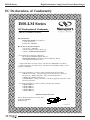
1
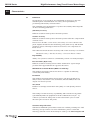
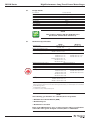
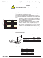
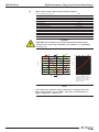
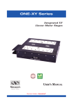
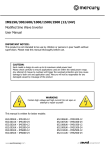
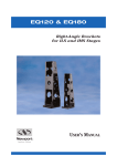
IMS-LM Series
SP
E
CI
ANTE
NS
AR
ED
GU
High-Performance Long-Travel
Linear Motor Stages
F I C AT
IO
RoHS
Compliant
USER’S MANUAL
IMS-LM Series
High-Performance Long-Travel Linear Motor Stages
Warranty
Newport Corporation warrants this product to be free from defects in
material and workmanship for a period of 1 year from the date of
shipment. If found to be defective during the warranty period, the product
will either be repaired or replaced at Newport’s discretion.
To exercise this warranty, write or call your local Newport representative,
or contact Newport headquarters in Irvine, California. You will be given
prompt assistance and return instructions. Send the instrument,
transportation prepaid, to the indicated service facility. Repairs will be
made and the instrument returned, transportation prepaid. Repaired
products are warranted for the balance of the original warranty period, or
at least 90 days.
Limitation of Warranty
This warranty does not apply to defects resulting from modification or
misuse of any product or part.
CAUTION
Warranty does not apply to damages resulting from:
CAUTION
Please return equipment in
the original (or equivalent)
packing.
You will be responsible for
damage incurred from
inadequate packaging if the
original packaging is not
used.
• Incorrect usage:
– Load on the stage greater than maximum specified load.
– Carriage speed higher than specified speed.
– Improper grounding.
¬ Connectors must be properly secured.
¬ When the load on the stage represents an electrical risk, it must
be connected to ground.
– Excessive or improper cantilever loads.
• Modification of the stage or any part thereof.
This warranty is in lieu of all other warranties, expressed or implied,
including any implied warranty of merchantability or fitness for a
particular use. Newport Corporation shall not be liable for any indirect,
special, or consequential damages.
No part of this manual may be reproduced or copied without the prior
written approval of Newport Corporation.
This manual has been provided for information only and product
specifications are subject to change without notice. Any changes will be
reflected in future printings.
EDH0208En1030 — 09/15
ii
IMS-LM Series
High-Performance Long-Travel Linear Motor Stages
Table of Contents
Warranty .................................................................................................................ii
EC Declaration of Conformity...............................................................................v
Definitions and Symbols.......................................................................................vi
Warnings ...............................................................................................................vii
Cautions .................................................................................................................ix
1.0
— Introduction .................................................................................1
2.0
— Description ...................................................................................2
3.0
— Stage Installation .......................................................................3
3.1 Unpacking ..................................................................................................3
3.2 Mounting Conditions ................................................................................3
4.0
4.1
4.2
4.3
4.4
— Connection to Newport Controllers ................................4
Operating with Newport Controllers/Drives .........................................4
Warnings on Controllers ..........................................................................4
Connection.................................................................................................5
Cables .........................................................................................................6
5.0
— Connection to Non-Newport Controllers ......................6
6.0
— Characteristics ............................................................................7
6.1
6.2
6.3
6.4
6.5
6.6
6.7
6.8
6.9
7.0
Definitions ..................................................................................................7
Design Details ............................................................................................8
Mechanical Specifications .......................................................................8
Hard Stop: Speed Limitation Versus Load .............................................9
Load Characteristics and Stiffness .........................................................9
Stage Weights ............................................................................................9
Motor characteristics (Direct Drive Brushless Motor)......................10
Encoder ....................................................................................................11
Sensor Positions......................................................................................11
— Connectors and Cables ........................................................12
7.1 Pinouts......................................................................................................12
Motor Connector (P1 – SUB-D9 Male) ..................................................12
Encoder Connector (P2 – SUB-D15 Male) ............................................12
End-of-Runs & Thermistor Connector (P3 – SUB-D9 Female)............12
7.2 IMS-LM Cable Wiring...............................................................................13
iii
EDH0208En1030 — 09/15
IMS-LM Series
High-Performance Long-Travel Linear Motor Stages
8.0
— Dimensions .................................................................................14
8.1 (M-)IMS-LM Stages ..................................................................................14
8.2 Top Plate Interface..................................................................................15
8.3 Cable Chains ............................................................................................15
9.0
— Maintenance ..............................................................................16
9.1 Maintenance ............................................................................................16
9.2 Repair .......................................................................................................16
9.3 Calibration ...............................................................................................16
Service Form .........................................................................................................17
EDH0208En1030 — 09/15
iv
IMS-LM Series
High-Performance Long-Travel Linear Motor Stages
EC Declaration of Conformity
IMS-LM Series
EC Declaration of Conformity
following Annex II-1A
of Directive 2006/42/EC on machinery
The manufacturer:
MICRO-CONTROLE Spectra-Physics,
9, rue du bois sauvage
F-91055 Evry FRANCE
Hereby declares that the machinery:
Description: " IMS-LM "
Function: High performance linear stage
Models: M-/IMS300/400/500/600/LM
– the technical file of which was compiled by:
Mr Dominique DEVIDAL, Quality Director,
MICRO-CONTROLE Spectra-Physics, Zone Industrielle - B.P.29
F-45340 Beaune La Rolande France
– complies with all the relevant provisions of the Directive 2006/42/EC on machinery.
– complies with all the relevant provisions of the Directive 2014/30/EU relating to electromagnetic compatibility.
– was designed and built in accordance with the following harmonised standards:
NF EN 61326-1:2013 « Electrical equipment for measurement, control and
laboratory use – EMC requirements – Part 1: General requirements »
NF EN 55011:2010/A1:2011 Class A
EN ISO 60204-1 « Safety of machinery – Electrical equipment of machines – Part 1
General requirements »
– was designed and built in accordance with the following other standards:
NF EN 61000-4-2
NF EN 61000-4-3
NF EN 61000-4-4
NF EN 61000-4-6
NF EN 61000-4-8
ORIGINAL DECLARATION
Done in Beaune La Rolande on 26 June 2015
Dominique DEVIDAL
Quality Director
DC1-EN rev:A
v
EDH0208En1030 — 09/15
IMS-LM Series
High-Performance Long-Travel Linear Motor Stages
Definitions and Symbols
The following terms and symbols are used in this documentation and also
appear on the product where safety-related issues occur.
General Warning or Caution
The exclamation symbol may appear in warning and caution tables in this
document. This symbol designates an area where personal injury or
damage to the equipment is possible.
The following are definitions of the Warnings, Cautions and Notes that may
be used in this manual to call attention to important information regarding
personal safety, safety and preservation of the equipment, or important
tips.
WARNING
Warning indicates a potentially dangerous situation which can result in
bodily harm or death.
CAUTION
Caution indicates a potentially hazardous situation which can result in
damage to product or equipment.
NOTE
Note indicates additional information that must be considered by the
user or operator.
European Union CE Mark
The presence of the CE Mark on Newport Corporation equipment means
that it has been designed, tested and certified as complying with all
applicable European Union (CE) regulations and recommendations.
Warnings and Cautions
ATTENTION
This stage is a Class A device. In a residential environment, this device
can cause electromagnetic interference. In this case, suitable measures
must be taken by the user.
EDH0208En1030 — 09/15
vi
IMS-LM Series
High-Performance Long-Travel Linear Motor Stages
WARNING
When the IMS-LM stage is installed or combined with other instruments
in a machine, additional testing to directive 2006/42/EC may be
required. It is the responsibility of the end-user or integrator to perform
a risk-analysis and the necessary tests to conform to the EC directives.
Newport is not liable for damages caused by not executing this
responsibility.
Warnings
WARNING
The motion of objects of all types carries potential risks for operators.
Ensure the protection of operators by prohibiting access to the dangerous
area and by informing the personnel of the potential risks involved.
WARNING
The magnetic channel included in this device has the potential to disrupt
pacemakers. Consequently, it is recommended that individuals maintain a
distance of 1 meter or more from the stage as a precautionary measure.
WARNING
Do not use this stage when its motor is emitting smoke or is unusually
hot to the touch or is emitting any unusual odor or noise or is in any
other abnormal state.
Stop using the stage immediately, switch off the motor power and then
disconnect the electronics power supply.
After checking that smoke is no longer being emitted contact your
Newport service facility and request repairs. Never attempt to repair the
stage yourself as this can be dangerous.
WARNING
Make sure that this stage is not exposed to moisture and that liquid does
not get into the stage.
Nevertheless, if any liquid has entered the stage, switch off the motor
power and then disconnect the electronics from power supply.
Contact your Newport service facility and request repairs.
vii
W
EDH0208En1030 — 09/15
IMS-LM Series
High-Performance Long-Travel Linear Motor Stages
WARNING
Do not insert or drop objects into this stage, this may cause an electric
shock, or lock the drive.
Do not use this stage if any foreign objects have entered the stage.
Switch off the motor power and then disconnect the electronics power
supply.
Contact your Newport service facility for repairs.
WARNING
Do not place this stage in unstable locations such as on a wobbly table or
sloping surface, where it may fall or tip over and cause injury.
If this stage has been dropped or the case has been damaged, switch off
the motor power and then disconnect the electronics power supply.
Contact your Newport service facility and request repairs.
WARNING
Do not attempt to modify this stage; this may cause an electric shock or
downgrade its performance.
WARNING
Do not exceed the usable depth indicated on the mounting holes (see
section “Dimensions”). Longer screws can damage the mechanics or
cause a short-circuit.
WARNING
Do not exceed speed and load limitations as specified in this manual.
EDH0208En1030 — 09/15
viii
IMS-LM Series
High-Performance Long-Travel Linear Motor Stages
Cautions
CAUTION
Do not place this stage in a hostile environment such as X-Rays, hard
UV,… or in any vacuum environment.
CAUTION
Do not place this stage in a location affected by dust, oil fumes, steam or
high humidity. This may cause an electric shock.
CAUTION
Do not leave this stage in places subject to extremely high temperatures
or low temperatures. This may cause an electric shock.
• Operating temperature: +10 to +35 °C
• Storage/Operating altitude: 1000 m
• Storage/Operating humidity: 85%
• Storage temperature: -10 to +40 °C (in its original packaging)
CAUTION
Do not move this stage if its motor power is on.
Make sure that the cable to the electronics is disconnected before
moving the stage. Failure to do so may damage the cable and cause an
electrical shock.
CAUTION
Be careful that the stage is not bumped when it is being carried. This
may cause it to malfunction.
CAUTION
When handling this stage, always unplug the equipment from the power
source for safety.
CAUTION
When the carriage is in its end-of-run position, it is strongly recommended
not to go beyond this point as this may damage the stage mechanism.
CAUTION
Contact your Newport service facility to request cleaning and
specification control every year.
ix
EDH0208En1030 — 09/15
IMS-LM Series
EDH0208En1030 — 09/15
High-Performance Long-Travel Linear Motor Stages
x
IMS-LM Series
High-Performance Long-Travel Linear Motor Stages
High-Performance Long-Travel
Linear Motor Stages
IMS-LM Series
1.0 —Introduction
This manual provides operating instructions for the IMS-LM stage that you
have purchased.
Inside this manual you will find useful information and technical
references. It is recommended the user download all support
documentation from the IMS-LM page of the Newport website to have as
reference.
(M-)IMS600LM & (M-)IMS300LM Stages.
RECOMMENDATION
We recommend you carefully read the chapter “Connection to
electronics” before using the (M-)IMS-LM stage.
1
EDH0208En1030 — 09/15
IMS-LM Series
High-Performance Long-Travel Linear Motor Stages
2.0 —Description
The IMS-LM series of linear motor stages are designed for self-supporting
applications with travel ranges from 300 mm to 1200 mm. The stages
feature a robust design with high performance at low cost, making them
cost-effective solutions for precision industrial applications such as
semiconductor wafer inspection, microelectronics test and assembly, pick
and place, DNA sequencing, or laser machining. The IMS-LM-SA version
with, 4-point mounting, is ideal for delay lines and other applications with
non-flat mounting surfaces.
The IMS-LM series utilizes an FEM optimized extruded aluminum body that
is extremely stiff and minimizes bending caused by different thermal
expansion coefficients of the aluminum body and steel rails.
Unlike-screw driven stages, the IMS-LM employs a center-driven linear
motor. This linear motor is absolutely noise-free and has the advantage of
higher speed, acceleration and system responsiveness without wear on
motor brushes or drive screws. Due to the fully integrated linear motor,
the IMS-LM is more than 100 mm shorter in length than a comparable
screw driven stage. Thus, the IMS-LM is the optimum solution for space
constrained applications that require high-throughput, high reliability, and
ultra-quiet operation.
The IMS-LM uses a high efficiency 3-phase synchronous ironcore linear
motor. While ironcore linear motors are often criticized for their cogging
and high attractive forces, their efficiency is almost twice the efficiency of
ironless linear motors. This results in higher acceleration capability and
significantly less heat generation, which often limits performance of rapid
point-to-point positioning.
Recirculating ball bearing slides with caged balls provide excellent
payload capacity and long life. The ball separators in the recirculating
elements ensure superior smooth movement, lower noise, and longer
service life compared to uncaged ball bearing slides.
Precision position feedback is supplied by a highly repeatable linear scale
mounted inside the stage. The encoder signals are interpolated by
Newport’s motion controllers with outstanding 20 nm Minimum
Incremental Motion, repeatability, and stability. Absolute home position
and limit signals are incorporated to improve repeatability and reliability,
while simplifying the design with less electronics and mechanical parts.
EDH0208En1030 — 09/15
2
IMS-LM Series
High-Performance Long-Travel Linear Motor Stages
3.0 —Stage Installation
3.1
Unpacking
The (M-)IMS-LM stage will be delivered to your site in packaging designed
for safe transport. Attached to the body of the stage are handles for safe
removal from packaging. It is recommended to carefully lift the stage from
packaging using these handles.
The stage will come delivered with a control report that indicates
performance of your stage within guaranteed specification. These
measurements were taken in a controlled environment under flat mounting
conditions.
3.2
Mounting Conditions
(M-)IMS-LM-SA stages feature a four-point mounting which is ideal for
operation on non-flat surfaces. However it is recommended for all (M-)IMSLM and (M-)IMS-LM-SA stages that the following mounting conditions be
adhered to for best performance.
Installation Considerations
Mounting surface flatness
Payload surface flatness
Mounting Screw torque
3
5 µm
10 µm
7 Nm
EDH0208En1030 — 09/15
IMS-LM Series
High-Performance Long-Travel Linear Motor Stages
4.0 —Connection to Newport Controllers
NOTE
Visit www.newport.com for compatible Newport controllers.
4.1
Operating with Newport Controllers/Drives
Newport provides detailed documentation for connecting and configuring
(M-)IMS-LM stages with compatible Newport controllers/drives. Newport
controllers proprietary plug-and-play ESP technology will automatically
load configuration parameters for the stage based on best factory settings
in a no load condition. These configurations can be adjusted for optimal
operation under various applications and load conditions. Refer to
documentation available on the IMS-LM Series Page for additional
information.
4.2
Warnings on Controllers
Controllers are intended for use by qualified personnel who recognize
shock hazards and are familiar with safety precautions required to avoid
possible injury. Read the controller user’s manual carefully before
operating the instrument and pay attention to all written warnings and
cautions.
Specifications listed in this guide are based on operation with Newport
Control and Drive Electronics. The Newport controllers with ESP
technology are delivered with a configuration file that has been developed
at the factory for operation in a no-load condition for immediate plug-andplay operation.
WARNING
Disconnect the power plug under the following circumstances:
• If the power cord or any attached cables are frayed or damaged in
any way.
• If the power plug is damaged in any way.
• If the unit is exposed to rain, excessive moisture, or liquids are spilled
on the unit.
• If the unit has been dropped or the case is damaged.
• If you suspect service or repair is required.
• Whenever you clean the electronics unit.
CAUTION
To protect the unit from damage, be sure to:
• Keep all air vents free of dirt and dust.
• Keep all liquids away from the unit.
• Do not expose the unit to excessive moisture (85% humidity).
• Read this manual before using the unit for the first time.
EDH0208En1030 — 09/15
4
IMS-LM Series
High-Performance Long-Travel Linear Motor Stages
WARNING
All attachment plug receptacles in the vicinity of this unit are to be of
the grounding type and properly polarized.
Contact your electrician to check your receptacles.
WARNING
This product is equipped with a 3-wire grounding type plug.
Any interruption of the grounding connection can create an electric
shock hazard.
If you are unable to insert the plug into your wall plug receptacle,
contact your electrician to perform the necessary alterations to ensure
that the green (green-yellow) wire is attached to earth ground.
WARNING
This product operates with voltages that can be lethal.
Pushing objects of any kind into cabinet slots or holes, or spilling any
liquid on the product, may touch hazardous voltage points or short out
parts.
4.3
Connection
On each stage is represented a label which indicates its name and its serial
number.
WARNING
Always turn the controller's power OFF before connecting to a stage.
Stages may be connected to the rear panel motor connectors any time
prior to power-up with the supplied cable assemblies.
NOTE
These stages are ESP compatible. Enhanced System Performance is
Newport's exclusive technology that enables Newport ESP motion
controllers to recognize the connected Newport ESP stage and upload
the stage parameters. This ensures that the user can operate the motion
system quickly and safely.
5
EDH0208En1030 — 09/15
IMS-LM Series
High-Performance Long-Travel Linear Motor Stages
4.4
Cables
(M-)IMS-LM stages are delivered with a set of three 5-meter cables that can
be directly connected to the Newport controller.
WARNING
IMS-LM Series translation stages can only operate with cable lengths of
5 m or less.
WARNING
These cables are shielded. For correct operation, make sure to lock
connectors (ground continuity provided by cables).
WARNING
Keep the cables at a safe distance from other electrical cables in your
environment to avoid potential cross talk.
5.0 —Connection to Non-Newport Controllers
Newport stages can be operated with Non-Newport controllers. However,
under such operational conditions Newport makes no guarantee regarding
achievable specifications. To aid Newport customers using non-Newport
Controllers with (M-)IMS-LM stages we have provided wiring conventions
and motor characteristics below. It should be noted, damage caused by
improper configuration or operation while in use with non-Newport
controllers is not covered by the warranty.
Please refer to Design Details and Specifications for more information to
help configure the stage with your controller. Newport also provides a
tech note on configuring third party stages with Newport controllers on
IMS-LM website, which may be useful as a reference.
WARNING
Newport takes no responsibility for improper functioning or damage of
a stage when it is used with any non- Newport controllers.
WARNING
• Maximum peak voltage: 100 Vpeak
• Maximum rms current: 3.1 Arms.
EDH0208En1030 — 09/15
6
IMS-LM Series
High-Performance Long-Travel Linear Motor Stages
6.0 —Characteristics
6.1
Definitions
Specifications of our products are established in reference to ISO 230
standard part II “Determination of accuracy and repeatability of
positioning numerically controlled axes”.
This standard gives the definition of position uncertainty which depends
on the 3 following parameters:
(Absolute) Accuracy
Difference between ideal position and real position.
On-Axis Accuracy
Difference between ideal position and real position after the compensation
of linear errors.
Linear errors include: cosine errors, inaccuracy of screw or linear scale
pitch, angular deviation at the measuring point (Abbe error) and thermal
expansion effects. All Newport motion electronics can compensate for
linear errors.
The relation between absolute accuracy and on-axis accuracy is as follows:
Absolute Accuracy = On-Axis Accuracy + Correction Factor x Travel
Repeatability
Ability of a system to achieve a commanded position over many attempts.
Reversal Value (Hysteresis)
Difference between actual position values obtained for a given target
position when approached from opposite directions.
Minimum Incremental Motion (MIM or Sensitivity)
The smallest increment of motion a device is capable of delivering
consistently and reliably.
Resolution
The smallest increment that a motion device can theoretically move
and/or detect. Resolution is not achievable, whereas MIM, is the real
output of a motion system.
Yaw, Pitch
Rotation of carriage around the Z axis (Yaw) or Y axis (Pitch), when it
moves.
The testing of on-axis accuracy, repeatability, and reversal error are made
systematically with test equipment in an air-conditioned room (20 ±1 °C).
A linear cycle with 21 data points on the travel and 4 cycles in each
direction gives a total of 164 points.
Guaranteed Specifications
Guaranteed maximum performance values are verified per Newport's A167
metrology test procedure. For more information, please consult the
metrology tutorial section in the Newport catalog or at www.newport.com
7
EDH0208En1030 — 09/15
IMS-LM Series
High-Performance Long-Travel Linear Motor Stages
6.2
Design Details
Base Material
Bearings
Drive System
Motor Initialization
Feedback
Limit Switches
Home Switch
ESP Compatibility
Cable
MTBF
Extruded Aluminum
Recirculating bearings with caged balls
3-phase synchronous ironcore linear motor (no Hall effect sensors)
Has to be done by the controller (without using Hall effect sensors)
Linear steel scale, 20 µm signal period, 1 Vpp
Optical
Optical, on encoder’s fiducial track, located at center of travel
Yes
5 m long cables included
20,000 hours
NOTE
RoHS
This product complies with the RoHS directive
(Restriction of Hazardous Substances).
Compliant
6.3
Mechanical Specifications
IMS-LM
300, 400, 500, 600,
800, 1000, 1200
Travel Range (mm)
IMS-LM-SA
800, 1000, 1200
SP
E
CI
ANTE
NS
AR
ED
GU
Minimum Incremental Motion (nm)
Bidirectional Repeatability (1) (µm)
F I C ATI O
20
IMS300 to 600-LM: 0.5 or ±0.25
1 or ±0.5
IMS800 to 1200-LM: 1 or ±0.5
On-Axis Accuracy (1) (µm)
IMS300-LM: 9 or ±4.5
IMS800-LM-SA: 20 or ±10
IMS400-LM: 11 or ±5.5
IMS1000-LM-SA: 25 or ±12.5
IMS500-LM: 15 or ±7.5
IMS1200-LM-SA: 30 or ±15
IMS600 and 800-LM: 20 or ±10
IMS1000-LM: 25 or ±12.5
IMS1200-LM: 30 or ±15
Maximum Speed (No Load) (2) (mm/s)
1000 (refer to chart below)
Maximum Acceleration (No Load) (2) (m/s2)
40
Moving mass (kg)
Carriage:3.5 + Interface:1 = 4.5
Drag force (torque)
Approx. 15 N
Pitch (1) (3) (µrad)
IMS300 to 500-LM: 150 or ±75
IMS800-LM-SA: 400 or ±200
IMS600-LM: 250 or ±125
IMS1000-LM-SA: 450 or ±225
IMS800-LM: 500 or ±250
IMS1200-LM-SA: 500 or ±250
IMS1000-LM: 550 or ±275
IMS1200-LM: 600 or ±300
Yaw (1) (3) (µrad)
IMS300-LM: 100 or ±50
300 or ±150
IMS400 to 600-LM: 150 or ±75
IMS800 to 1200-LM: 300 or ±150
1)
Shown are peak to peak, guaranteed specifications or ±half the value as sometimes shown. For the definition of
typical specifications which are about 2X better than the guaranteed values, visit www.newport.com for the Motion
Control Metrology Primer.
2)
Speed depends on the driver.
3)
To obtain arcsec units, divide µrad value by 4.8.
NOTE
The following specifications are controller/driver dependent:
• Minimum Incremental Motion (MIM)
• Maximum Speed
• Maximum Acceleration
Refer to the IMS-LM Series page on www.newport.com for specifications
achievable with specific Newport controller/driver combination.
EDH0208En1030 — 09/15
8
IMS-LM Series
High-Performance Long-Travel Linear Motor Stages
CAUTION
To reach stated specifications, the stages must be fixed on a plane
surface with a flatness of 5 µm.
6.4
Hard Stop: Speed Limitation Versus Load
(M-)IMS-LM stage uses electrical end-of-run and elastomer hard stops to
stop the carriage as smoothly as possible past the end-of-runs. The
overtravel allowed by the hard stops is 8 mm.
When the stage is used with Newport controllers, the factory settings of
the "software limits" prohibit any commanded motion beyond this travel
range.
Nevertheless, for safety reasons, follow the recommendations
above to minimize risk of mechanical damage, in case of failure
or incorrect adjustment of parameters.
Maximum Speed for Hard Stoppers
1000
920
840
The maximum speed of the stage must be limited so that the
hard stops will always stop the carriage in 8 mm or less, to
avoid any shock between the carriage and stage body.
Speed (mm/s)
760
680
600
The graph at left, provides stage speed as a function of applied
load. This curve defines allowed operating conditions to stop
within the 8 mm over-travel allowed by the hard stops. To stop
within this distance, the user must maintain speed and load
within this tolerance. This graph assumes correct wiring of the
electrical end of runs will cut motor power before contact with
the hard stop.
520
440
360
280
200
0
5
10
15
20
25
30
35
40
45
50
55
60
Load on Carriage (kg)
6.5
Load Characteristics and Stiffness
Normal Load Capacity (Cz)
Maximum load a stage can move while maintaining specifications.
Z
QH
D
Y
Cz
X
6.6
Cz, Normal center load capacity on bearings
kax, Angular stiffness (Roll)
kay, Angular stiffness (Pitch)
kaz, Angular stiffness (Yaw)
Q, Off-center load
D, Cantilever distance in mm
IMS-LM
IMS-LM-SA
600 N
100 N
1 µrad/Nm
2 µrad/Nm
0.2 µrad/Nm
2 µrad/Nm
1 µrad/Nm
1 µrad/Nm
Q ≤ Cz/(1 + D/90)
Stage Weights
Weight [lb (kg)]
IMS300
IMS400
IMS500
IMS600
IMS800
IMS1000
IMS1200
9
-LM
37.5 (17)
41.9 (19)
46.3 (21)
50.7 (23)
52.9 (24)
61.7 (28)
70.5 (32)
-LM-SA
–
–
–
–
52.9 (24)
61.7 (28)
70.5 (32)
EDH0208En1030 — 09/15
IMS-LM Series
High-Performance Long-Travel Linear Motor Stages
6.7
Motor characteristics (Direct Drive Brushless Motor)
Magnet Pitch (Commutation period)
Motor constant
Force sensitivity
Back-emf constant
Motor resistance
Motor inductance
Thermal resistance
Max. speed @ Max. voltage
Peak current
Peak force
Max. rms current
Max. rms force
Temperature Sensor
24 mm
180 N2/W
38.9 N/Arms
31.7 V/m/s
5.6 Ω
36 mH
0.7 °C/W
8 m/s @ 560 V
6 Arms
210 N
3.1 Arms
120 N
PTC, 1 kΩ
CAUTION
High RMS current will generate motor heating which will degrade
characteristics of the stage, including such attributes as repeatability,
accuracy, etc…
Induced Voltages Coil Moving
U-V
V-W
U-W
2
EHA07248
2500
1.5
2000
0.5
1500
RT (Ω)
Amplitude
1
0
1000
-0.5
-1
500
-1.5
-2
0
-50
Motion
Direction +
0
50
100
150
TA (°C)
Positive Temperature Coefficient
Thermistor, resistance as a function
of temperature. Motor heating is
typically restricted to 20 °C with
Newport Controllers.
NOTE
The values above indicate voltage induced by energized coil of one
phase on next phase coil. A positive value for U-V would indicate a
higher voltage on U relative to V.
EDH0208En1030 — 09/15
10
IMS-LM Series
High-Performance Long-Travel Linear Motor Stages
6.8
Encoder
Signal description / Voltage / wiring
Reference mark position
Resolution
Maximum speed
Heidenhain standard 1 Vpp
see drawing "Sensor Positions"
Scale pitch 20 µm
8 m/s
Encoder Feedback Signal Position
1
Encoder
Phase A
Encoder
Phase A
2
3
4
High
Low
High
Direction +
Low
High
Encoder
Phase B
Encoder
Phase B
Low
High
Low
Direction –
6.9
Motion
Direction +
Sensor Positions
P1
P2
P3
Direction +
X
X Values
(mm)
(M-)IMS300LM
(M-)IMS400LM
(M-)IMS500LM
(M-)IMS600LM
(M-)IMS800LM(-SA)
(M-)IMS1000LM(-SA)
(M-)IMS1200LM(-SA)
– Hard
Limit
126.5 -80
126.5 -80
126.5 -80
126.5 -80
144.5 -80
144.5 -80
144.5 -80
– End-of-Run
Limit
128 ±0.5
128 ±0.5
128 ±0.5
128 ±0.5
160 ±0.5
160 ±0.5
160 ±0.5
Mech.
Zero
279 ±0.25
329 ±0.25
379 ±0.25
429 ±0.25
564.5 ±0.25
664.5 ±0.25
764.5 ±0.25
Home
Position
279.5 ±0.25
329.5 ±0.25
379.5 ±0.25
429.5 ±0.25
565 ±0.25
665 ±0.25
765 ±0.25
+ End-of-Run
Limit
431 ±0.5
481 ±0.5
531 ±0.5
581 ±0.5
970 ±0.5
1170 ±0.5
1370 ±0.5
+ Hard
Limit
732.5 +80
732.5 +80
732.5 +80
732.5 +80
980.5 +80
1180.5 +80
1380.5 +80
Sensor Positions
Stage Travel Range
Negative
Software Limit
Home Position
(Origin)
.06 (1.5) for (M-)IMS300 to 600LM
.197 (5) for (M-)IMS800 to 1200 LM(SA)
Positive
Software Limit
.06 (1.5) for (M-)IMS300 to 600LM
.197 (5) for (M-)IMS800 to 1200 LM(SA)
.02 (.5)
– End-of-Run Limit
+ End-of-Run Limit
Mechanical Zero
Index Pulse
Index Pulse
1.97
(50)
Direction –
Motion
Direction +
Dimensions in inches
(and millimeters)
11
EDH0208En1030 — 09/15
IMS-LM Series
High-Performance Long-Travel Linear Motor Stages
7.0 —Connectors and Cables
7.1
Pinouts
Sub-D pin outs for (M-)IMS-LM stages are provided in the following tables:
7.1.1
Motor Connector (P1 – SUB-D9 Male)
1
2
3
4
5
6
7
8
9
5
1
6
9
U Motor
U Motor
V Motor
V Motor
Thermistor 1
W Motor
W Motor
Shield Ground
Thermistor 2
• Max. voltage: 96 V
• Max. rms Current: 3.1 A
WARNING
GROUNDING: The stage's protective ground is located on pin #8 of the
motor power connector.
If you are using grounds other than those provided by Newport, you
must connect pin #8 to a ground connection.
7.1.2
Encoder Connector (P2 – SUB-D15 Male)
1
8
9
7.1.3
15
Encoder Phase B
Shield Ground
Encoder Phase A
Encoder Power: + 5 V
N.C.
N.C.
Index Pulse /I
N.C.
Encoder Phase /B
N.C.
Encoder Phase /A
N.C.
N.C.
Index Pulse I
N.C.
End-of-Runs & Thermistor Connector (P3 – SUB-D9 Female)
5
1
9
EDH0208En1030 — 09/15
1
2
3
4
5
6
7
8
9
10
11
12
13
14
15
12
6
1
2
3
4
5
6
7
8
9
+ End-of-Run
- End-of-Run
Mechanical Zero
N.C.
EOR Power: + 5 V
Thermistor 1
Shield Ground
Thermistor 2
Shield Ground
IMS-LM Series
High-Performance Long-Travel Linear Motor Stages
IMS-LM Cable Wiring
All (M-)IMS-LM stages are delivered with the three cables required for
operation. The wiring diagrams and connectors for these cables are
provided in the following diagrams. When operating the non-Newport
controllers, it is recommended to adhere to the wiring conventions
presented here and to use cabling with similar characteristics.
WARNING
Newport guarantees “ ” compliance of the (M-)IMS-LM translation
stages only if they are used with Newport cables and controllers.
Sub-D9M
Connector
Sub-D9F
Connector
Motor
1
2
3
4
6
7
Phase U Motor
Phase U Motor
Phase V Motor
Phase V Motor
Phase W Motor
Phase W Motor
8
Connector
Cap
Ground
Connector
Cap
Encoder
Sub-D15M
Connector
Sub-D15F
Connector
3
11
1
9
14
7
4
6
8
Encoder Phase A
Encoder Phase /A
Encoder Phase B
Encoder Phase /B
Index Pulse I
Index Pulse /I
+5 V
N.C.
N.C.
2
Connector
Cap
Ground
Connector
Cap
Sub-D9F
Connector
End-of-Runs &
Thermistance
7.2
Sub-D9M
Connector
1
2
3
5
6
8
+ End-of-Run
- End-of-Run
Mechanical Zero
+5 V
Thermistance 1
Thermistance 2
7
Connector
Cap
Ground
Connector
Cap
NOTE
This is the wiring of the cables that provided with the connection to
Newport Controllers, for third party controllers, we recommend using a
cable with similar characteristics: Chapters 7.1 (Pinouts) and 7.2 (IMSLM Cable Wiring).
13
EDH0208En1030 — 09/15
IMS-LM Series
High-Performance Long-Travel Linear Motor Stages
8.0 —Dimensions
8.1
(M-)IMS-LM Stages
L
MODEL SHOWN: IMS300LM
7.09
(180)
DIMENSIONS IN INCHES (AND MILLIMETERS)
SIDE VIEW
(M-)IMS300LM TO (M-)IMS600LM
7.05
(179)
3.54
(90)
1.10
(28)
.83
(21)
.83
(21)
5.91 (150)
5.91 (150)
5.91 (150)
SIDE VIEW
(M-)IMS800LM(-SA) TO (M-)IMS1200LM(-SA)
n1 x 2 HOLES CLR
FOR M6 SCREW
5.91
(150)
6.0
(152.4)
5.0 (127)
5.0 (127)
4.36
(111)
7.09
(180)
5.0 (127)
MODEL (METRIC)
(M-)IMS300LM
(M-)IMS400LM
(M-)IMS500LM
(M-)IMS600LM
(M-)IMS800LM
(M-)IMS1000LM
(M-)IMS1200LM
(M-)IMS800LM-SA
(M-)IMS1000LM-SA
(M-)IMS1200LM-SA
n1
n2
4
4
4
4
4
6
6
6
6
–
7
–
8
–
4 HOLES ON 26 x 6 (600 x 150)
4 HOLES ON 28 x 6 (750 x 150)
4 HOLES ON 34 x 6 (900 x 150)
TRAVEL
11.81 (300)
15.75 (400)
19.69 (500)
23.62 (600)
31.49 (800)
39.36 (1000)
47.23 (1200)
31.49 (800)
39.36 (1000)
47.23 (1200)
IMS800LM-SA stage.
EDH0208En1030 — 09/15
14
L
21.85 (555)
25.79 (655)
29.72 (755)
33.66 (855)
44.48 (1130)
52.35 (1330)
60.22 (1530)
44.48 (1130)
52.35 (1330)
60.22 (1530)
n2 x 2 HOLES CLR
FOR 1/4-20 SCREW
IMS-LM Series
High-Performance Long-Travel Linear Motor Stages
8.2
Top Plate Interface
5 HOLES M5 THD ON ø6.85 (174),
EQUIDISTANT AT 60°,
DEPTH: .35 (9)
5 HOLES M5 THD / ø5.39 (137),
EQUIDISTANT AT 60°,
DEPTH: .35 (9)
5 HOLES M4 THD
ON ø3.62 (92),
EQUIDISTANT AT 60°,
DEPTH: .31 (8)
SQR 7.05
(179)
.51 (13)
3.0
2.0
4.0
(50) 2.48 (75) 3.62 (100) 6.0
(92)
(63)
(150)
15°
22.5°
25°
4 CLEARANCE HOLES FOR
M6 SCREW BACK SIDE
1.0
(25)
2.0
(50)
2.48
(63)
4.0
(100)
4 HOLES M4 THD
ON 3.94 x 2.95 (100 x 75),
DEPTH: .31 (8)
37 HOLES 1/4-20 (M6) THD,
DEPTH: .39 (10)
6.14
(156)
8.3
DIMENSIONS IN INCHES (MILLIMETERS)
Cable Chains
NOTE
IMSLMC for stages with a travel of 300 to 600 mm
IMSLMC2 for stages with a travel of 800 to 1200 mm
IMSLMC cable chain for routing cables to the stationary
base. For cable management of XY assemblies, please
call Newport.
CARRIAGE FASTENING
2 CHC M4 X .31 (8) SCREWS
CABLE CHAIN INTERFAC
(REVERSIBLE)
CABLE CHAIN
MODEL SHOWN: IMS600LM
DIMENSIONS IN INCHES (AND MILLIMETERS)
HOLDER FOR
RIGHT-HAND OUTPUT
HOLDER FOR
LEFT-HAND OUTPUT
STAGE FASTENING
2 CHC M4 X .39 (10) SCREWS
15
EDH0208En1030 — 09/15
IMS-LM Series
High-Performance Long-Travel Linear Motor Stages
9.0 —Maintenance
RECOMMENDATION
It is recommended to contact our After Sales Service which will know to
define the appropriate maintenance for your application.
9.1
Maintenance
The (M-)IMS-LM stage requires no particular maintenance. Nevertheless,
this is a precision mechanical device that must be kept and operated with
caution.
PRECAUTIONS
The (M-)IMS-LM stage must be used or stocked in a clean environment,
without dust, humidity, solvents or other substances.
RECOMMENDATION
It is recommended to return your (M-)IMS-LM stage to Newport's After
Sales Service after every 2000 hours of use for lubrication.
If your stage is mounted on a workstation and cannot be easily
removed, please contact Newport's After Sales Service for further
instructions.
9.2
Repair
CAUTION
Never attempt to disassemble a component of the stage that has not
been covered in this manual.
To disassemble a non specified component can cause a malfunction of
the stage.
If you observe a malfunction in your stage, please contact us immediately
to arrange for a repair.
CAUTION
Any attempt to disassemble or repair a stage without prior
authorization will void your warranty.
9.3
Calibration
CAUTION
It is recommended to return your (M-)IMS-LM stage to Newport once a
year for recalibration to its original specifications.
EDH0208En1030 — 09/15
16
Service Form
Your Local Representative
Tel.:
Fax:
Return authorization #:
Name:
(Please obtain prior to return of item)
Company:
Address:
Date:
Country:
Phone Number:
P.O. Number:
Fax Number:
Item(s) Being Returned:
Model #:
Serial #:
Description:
Reasons of return of goods (please list any specific problems):
17
EDH0208En1030 — 09/15
Visit Newport Online at:
w w w. n e w p o r t . c o m
North America & Asia
Europe
Newport Corporation
MICRO-CONTROLE Spectra-Physics S.A.S
1791 Deere Ave.
Irvine, CA 92606, USA
9, rue du Bois Sauvage
91055 Évry CEDEX
France
Sales
Sales & Technical Support
Tel.: (800) 222-6440
Tel.: +33 (0)1.60.91.68.68
e-mail: [email protected]
e-mail: [email protected]
Technical Support
Service & Returns
Tel.: (800) 222-6440
Tel.: +33 (0)2.38.40.51.55
e-mail: [email protected]
Service, RMAs & Returns
Tel.: (800) 222-6440
e-mail: [email protected]