1
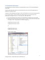
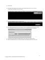
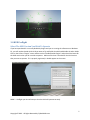
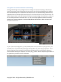
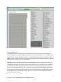
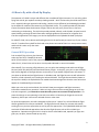
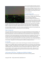
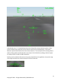
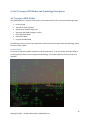
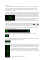
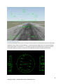
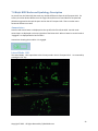
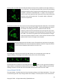
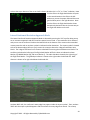
FlyRealHUDs Very Brief User’s Manual 1 Copyright © 2012 - All Rights Reserved by FlyRealHUDs.com 1.0 Welcome! Congratulations. You are about to become one of the elite pilots who have mastered the fine art of flying the most advanced piece of avionics in the modern cockpit – a Head Up Display. Also, thanks for choosing FlyRealHUDs.com’s Head Up Displays. We are confident you will love these very cool Head Up Displays. So, let’s get started. 2 Copyright © 2012 - All Rights Reserved by FlyRealHUDs.com 2.0 Installation Instructions The FlyRealHUDs.com Heads-Up Displays are compatible with X-Plane 9 or 10 on both MS Windows™ and the Mac. If you are new to the X-Plane world, you need to follow each step to ensure your FlyRealHUDs.com application is installed correctly. Installation of the FlyRealHUDs.com plugins is super easy. Basically all you have to do is drag the xpl files into the X-Plane “plugins” folder and start X-Plane and then type in your registration key in the FlyRealHUDs.com Registration form. It’s really that simple. More specifically: 1) Unzip the package that you received on your download for the software that you purchased. 2) Within the main X-Plane folder, locate the “Resources” folder, and then within that folder locate the “plugins” folder. Drag and drop the FlyRealHUDs plugin e.g., FlyRealHUDs-AirTransport-win.xpl FlyRealHUDs-AirTransport-mac.xpl or FlyRealHUDs-BizJet-win.xpl FlyRealHUDs-BizJet-mac.xpl into the “’plugins” folder. 3 Copyright © 2012 - All Rights Reserved by FlyRealHUDs.com 3) Start X-Plane 4) Go to the X-Plane Plugins menu and click on the FlyRealHUDs menu item, e.g., click the FlyRealHUDs-AirTransport menu item below: 5) Click on the Registration menu item that pops up: 6) The FlyRealHUDs Registration form will appear. Type in the Registration Key that you received in the FlyRealHUDs email that was sent to you after you purchased one of our products. 7) Click Save to indicate that you accept the EULA. Don’t worry, it’s a standard EULA. 8) After a valid Registration Key is entered, the HUD will immediately show up on the screen. 4 Copyright © 2012 - All Rights Reserved by FlyRealHUDs.com 3.0 HUD Preflight Select The HUD Version You Wish To Operate If you have purchased 2 or more FlyRealHUDs plugins and you are running the software on a Windows PC, you will need to decide which HUD you want to fly and Enable that HUD and disable the other HUDs. Click on the X-Plane “Plugins” menu and then select “Enable/Disable Plugins” and uncheck the boxes for the HUD version that you do not wish to operate. Make sure the box is checked for the HUD version that you want to operate. If it is properly registered, it should appear on the screen. NOW! — Preflight your aircraft setup so that the HUD will operate correctly. 5 Copyright © 2012 - All Rights Reserved by FlyRealHUDs.com Set up the Aircraft Instruments and Settings Each flight should begin with a preflight of the aircraft flight instruments and settings. Most X-Plane aircraft have a means to set the Barometric Pressure which you will also see displayed on the HUD just below the Altitude tape on the FlyRealHUDs AirTransport HUD. The selected heading, selected course, selected altitude and selected speed should also be set in X-Plane with your aircraft panel controls. The FlyRealHUDs simulator models will indicate all of the primary pilot settings. Also important – make sure the aircraft Flight Director is switched “ON” or you will have no flight guidance indication for heading, navigation or instrument approach. Check the OBS, BARO or Selected Course, DH or minimums and other pilot selection cues. As part of your setup configuration, you will probably want to set up a button on your joy stick or yoke to enable you to actuate the TOGA (take off go around) mode at any point during an approach. This is done by using the X-Plane settings for Joystick, Keys and Equipment to go to the Buttons Advanced screen and then selecting the “autopilot” and “take_off_go_around” buttons and pressing the button on the joystick that you want to use for TOGA mode. 6 Copyright © 2012 - All Rights Reserved by FlyRealHUDs.com Set the HUD View The FlyRealHUDs Head-Up Displays are all “conformal” HUDs. This means that the symbology will overlay or project onto the real world outside scene the way one would expect it to. For example, both the AirTransport HUD and the BizJet HUD have a runway symbol for the approach symbology. These runway outlines or edge lines will line up properly with the actual runway edge lines during an approach. The pitch ladder and horizon line are also conformal. VERY USEFUL NOTE: The conformal elements of the FlyRealHUDs are only conformal if you are in the “Forward with Nothing” View. Actually, they are also conformal in the “Forward with HUD” view but, the standard X-Plane HUD would appear as clutter behind the FlyRealHUDs head up display when you are in the “Forward with HUD” view. SO … normal operation with the FlyRealHUDs generally involves switching to the instrument panel to set up things like a selected altitude or a selected speed and then switching back to the “Forward with Nothing” view so that only the conformal FlyRealHUDs Head-Up Display appears on the screen. 7 Copyright © 2012 - All Rights Reserved by FlyRealHUDs.com In X-Plane 9 you can switch between these views by using the “W” key to get to the instrument panel and the “Shift-W” to get to the “Forward with Nothing” view. “In X-Plane 10 you can switch between these views by using the “W” key to get to the instrument panel and the “Ctrl-W” to get to the “Forward with Nothing” view. NOTE: EVS Imagery – To see what a real HUD looks like with Enhanced Vision, select the “I” key in XPlane 9 and the “Shift-N” key in X-Plane 10. This is especially cool to do at night. If you forget these keystrokes, you can find them in the X-Plane View menu. 8 Copyright © 2012 - All Rights Reserved by FlyRealHUDs.com 4.0 How to fly with a Head-Up Display The operation of a HUD is unique and different than a traditional flight instrument. For one thing, when flying with a HUD, your eyeballs are always looking outside – which is where they should be most of the time - especially during an approach and landing. Another major difference (and advantage) provided by the HUD over traditional instruments is the Flight Path Vector. This symbol provides the pilot with instant information about the direction of flight, and can also tell you if you are fast or slow and, accelerating or decelerating. The HUD also provides attitude, altitude, radio altitude, airspeed, vertical speed, heading, and angle of bank information and flight guidance information for navigation and instrument approaches. EVS imagery can also be displayed with the FlyRealHUDs head up displays. For takeoff, climb, cruise, descent and landing the HUD is the perfect way to control any of your X-Plane aircraft. Transition from takeoff to climb and cruise phases can now be flown in a more precise manner, and the HUD is easier to fly than most instruments. General HUD Operation Prior to takeoff, the pilot can also choose to select the Take Off or TakeOff/Go Around switch (TOGA mode) as well as the proper heading prior to takeoff. You will see Airspeed and speed values for V1, VR and V2 as well as other critical speeds indicated on some HUD models. After takeoff, if you are using a Flight Director, you can select the Heading mode and the HUD Flight Director (small little ball) will command the direction of flight. As the pilot, your job is to put the Flight Path Vector (Big Ball) on the flight director (cue) and fly it as you would a flight director instrument. If you select an altitude and put Flight Director in Altitude mode, the Flight Director cue will indicate the need for a climb or descent until reaching the selected altitude. The Flight Director Modes (shown at the top of the HUD) in the FlyRealHUDs.com models have been designed to show the same values that appear on a head down flight instrument. When you arrive at the cruise altitude, the HUD will show you navigation and flight instrument information needed for any operation. When arriving in the terminal area and getting set up for the instrument approach, just remember to treat the entire process as an actual aircraft operation. If it seems that things are not operating in the HUD, most often it is because you forgot the correct ILS frequency, did not put in the correct selected course or other item. For precision approaches, the HUD is designed to allow you to “capture” the ILS and follow the flight director guidance all the way to touchdown. The flight path vector allows for accurate and smooth tracking for non-precision approaches as well as precision approaches. The FlyRealHUDs HUDs will also work with all FMS selected approaches that drive the Flight Director such as GPS or VNAV type approaches. Operation using the HUD in visual or what is called VMC mode, especially at night, now gives you, the pilot, a better heads up way to fly. 9 Copyright © 2012 - All Rights Reserved by FlyRealHUDs.com Using the HUD and the Flight Path Vector on the approach, aim at the place you want to land, and control your speed and direction of flight. When you land, you will also get an indication for rollout guidance. The Takeoff / Roll For takeoff, you will maintain runway centerline and you will be monitoring airspeed values. You will note that V1, VR and V2 speeds are provided. The lower “zipper” on the outside of the airspeed tape shows stall speed – and yes, the picture to the right shows a stall speed condition. The airspeed trend arrow grows out of the middle point on the airspeed readout box and points to the predicted speed 5 seconds from now. At the moment of takeoff, the main task is aircraft pitch and climb and airspeed monitoring. After takeoff, select Heading or Navigation mode on the Flight Director and follow the FD cue with the Flight Path Vector symbol. Climb/Cruise With climb established, select the proper navigation means on the flight director mode control panel and selected course, and engage the NAV mode from the flight director to accomplish the enroute navigation. Once at the desired altitude, the ALT mode is engaged on the flight director, providing precise altitude cruise cues to the pilot. The FlyRealHUDs Head Up Displays provide vertical and lateral guidance information with clear directional cues to maintain the ATC-directed flight path. Our HUDs also display speed deviation, airspeed, ground speed, wind direction / speed, vertical speed, heading, attitude, barometric and radio altitude, and flight director modes. Descent During the descent, you can utilize the HUD to fly with guidance and navigation information for normal maneuvering and for instrument approaches. Descent and terminal operations can be conducted manually or on autopilot, with normal operation of the flight director. For example, suppose you wanted to descend to 5000 ft and turn to a magnetic heading of 320. This would be accomplished by setting the Flight Director into FLC (flight level change) mode and also ALT mode and then setting the Selected Heading and the Selected Altitude to the desired values. The Flight Director on the HUD will respond appropriately and provide the guidance to the desired altitude and heading. And if you are really feeling lazy, you can put the Flight Director into Autopilot mode after you have everything set up and sit back and watch the HUD and the Flight Director do their work. Approach For instrument approach use, our HUDs are operated exactly in accordance with the host PFD and flight director operation and using standard instrument approach procedures. Upon commencing standard instrument approach procedures, flight guidance is commanded on the flight director and is flown on the HUD system. Flight guidance, provided by the Flight Director mode control panel will either be Heading, Navigation or Approach type guidance, depending of the stage of flight. In the ILS approach, a 3-degree reference line, airport symbol and runway symbol will come into view. The value of the DH/DA 10 Copyright © 2012 - All Rights Reserved by FlyRealHUDs.com is set in the host PFD and verified in the HUD. At the Decision Height (DH) prescribed for the approach by the procedure the pilot verifies at the alerted DH that the visual references are in view and decides to land or begin the missed approach maneuver. Autopilot Approach If you select the autopilot for the approach, you can monitor the HUD and the aircraft, and even let the autopilot manage the autothrottles throughout the approach. On the upper right side of the HUD will be a CMD annunciator symbol showing that the autopilot is flying the aircraft. If you want to see how the HUD should be flown on an approach, it is worth a few minutes of your time to set up an autopilot approach into a known airport with a Cat III ILS and then set the AirTransport HUD in AIII Approach Mode or the BizJet HUD in Approach Mode and watch the way things interact – especially the Flight Director and Flight Path Marker. Then crank in some crosswinds (start small like 10 kts) and watch how that affects things on the HUD so that you get a feel for the symbology. Manual Approach Flying manual approaches with the HUD is easy once you get acquainted with the HUD symbology. Set yourself up at 10 nm out on final on an approach to a familiar runway without any crosswinds at first. After a few approaches, you will see the ease and precision with which you can fly an approach with a HUD.Fly the aircraft using the Flight Path Vector and the Flight director cue displayed on the HUD. The HUD will provide vertical and lateral guidance information necessary to complete the approach to landing. When you have selected the Flight Director modes to provide the vertical and lateral guidance with the ILS Localizer/Glideslope Approach Armed, the Flight Director (FD) and raw ILS data will lead you to an intercept. FD guidance cues are displayed to touchdown with Flight Path Vector. Go-Around To execute a missed approach, the pilot actuates the TOGA (go-around) button which which puts the Flight Director into TOGA mode and commands the Flight Director cue on the HUD. Once TOGA mode is engaged, you should use the flight path vector symbol to “chase" and overlay the flight director symbol. Initiating the go-around mode provides a pitch up and wings-level flight director command. A fixed pitch command is used if a manual speed is selected instead of automatic speed. When go-around airspeed and power are established, selecting the HDG and FLCH modes also provides the steering command to the Flight Director Cue. AirTransport HUD Flare, Touchdown and Rollout Guidance Both the AirTransport and the BizJet FlyRealHUDs provide a flare cue for flare guidance. 11 Copyright © 2012 - All Rights Reserved by FlyRealHUDs.com The flare cue for the AirTransport HUD consists of a flashing “+” symbol that appears below the Flight Path Vector and gradually rises to the center of the Flight Path Vector to indicate when the pilot should flare. The AirTransport HUD also indicates when the pilot should throttle back to idle which is annunciated just below the Flight Path Vector. After Touchdown the AirTransport HUD provides lateral rollout guidance with the symbology that looks a little like localizer guidance just below the Flight Path Vector and the Aircraft Reference symbol. This is especially helpful in night or IMC approaches and landings in very low category III conditions. A digital Runway Remaining Distance readout is also shown just below the RWY annunciator. 12 Copyright © 2012 - All Rights Reserved by FlyRealHUDs.com A deceleration caret “>”is located below and to the left side of the runway deviation symbols. When you hit the brakes that symbol will move to show you how fast you are decelerating. The runway deviation symbols show deviation from the runway centerline. The runway distance remaining readout and the rollout guidance and deceleration cues are part of the AIII Rollout symbology and don’t appear on landing rollout from IMC and VMC approaches. The flare cue for the BizJet HUD consists of two pairs of parallel lines that gradually rise up to the wings of the Flight Path Vector to provide a prompt for the flare maneuver. 13 Copyright © 2012 - All Rights Reserved by FlyRealHUDs.com 5.0 Keyboard Tips The FlyRealHUDs Head-Up Displays don’t take up lots of room on your disk but, they are packed with lots of features and capabilities. In order to get the full use of these features you will need to know a few keystrokes. We have put them into tables to make it easy to print these pages as a quick reference. AirTransport HUD Keystroke Quick Reference Keystroke H M V Other Modes (non-keyboard) Function Turns the HUD on and Off Changes modes depending on the conditions Primary IMC Approach Mode AIII Approach Mode No AIII Approach Mode VMC Approach Mode Toggles between VMC Mode and Primary Mode Rollout AIII Mode – automatically appears after touchdown on Cat III approach. Unusual Attitude Mode – automatically appears whenever o Pitch exceeds +35 degrees or -20 degrees or o Roll exceeds +/- 65 degrees. TOGA Mode – automatically appears whenever the Flight Director Mode is in Takeoff Go-Around Mode. BizJet HUD Keystroke Quick Reference Keystroke H M Backspace Escape Delete Other Modes (non-keyboard) Function Turns the HUD on and Off Changes modes depending on the conditions Lateral Mode HSI Lateral Mode FPM CDI Lateral Mode Conformal Deviation Lateral Mode Non-Conformal Deviation Flight Director with Wings and Roll Cue Toggle Flight Path Marker Caged vs. Uncaged Mode Toggle HUD Clear or Declutter Mode Unusual Attitude Mode – automatically appears whenever o Pitch exceeds +35 degrees or -20 degrees or o Roll exceeds +/- 65 degrees. TOGA Mode – automatically appears whenever the Flight Director Mode is in Takeoff Go-Around Mode. Stall – shows the maximum pitch angle symbol. 14 Copyright © 2012 - All Rights Reserved by FlyRealHUDs.com 6.0 Air Transport HUD Modes and Symbology Description Air Transport HUD Modes The FlyRealHUDs Air Transport HUD is similar to the HUDs used for 737’s and has the following modes: Primary Mode Take off Go Around (TOGA) Approach AIII Mode (Category III) Approach IMC Mode (Category I and II) Visual Approach Mode AIII Rollout Mode Unusual Attitude Mode The following sections will show you what these modes look like and explain what the symbology means for each of these modes. Primary Mode The primary mode is the default mode for the AirTransport HUD. It can be used for all modes of flight including takeoff, climb, cruise and approach and landing. This picture shows the Primary mode on an approach. 15 Copyright © 2012 - All Rights Reserved by FlyRealHUDs.com Annunciators The annunciators for different modes appear in set locations on the HUD. There are many different values these annunciators can take on depending upon the conditions that have been set up. The following shows some examples. In general the HUD annunciators are self-explanatory or match the annunciator values on the PFD. The HUD Mode in the Primary HUD shown previously is indicated by the “PRI” annunciator on the left side of the HUD just below the Localizer annunciator. The active HUD mode is shown in big characters. When a new HUD mode is selected, it will initially flash in small characters below the active mode for 5 seconds to indicate that a new HUD mode has been selected. After 5 seconds only the active HUD mode is shown in the annunciator location. If you select AIII mode on an approach to a runway that does not have a Category III ILS, the HUD will go to IMC mode and the “No AIII” annunciator will flash below the IMC mode annunciator to let you know that AIII Mode is not available for this approach. When the Localizer and Glideslope are captured this is indicated by the underlined “LOC1” and “G/S” as annunciators at the top of the HUD. All lateral mode annunciators are shown on the left, and vertical modes are shown on the right. Underlined annunciators indicate that the mode is captured or engaged. Non-underlined modes or, modes that are followed by the word “ARMED” indicate that the mode is armed but not captured or engaged. When the Autopilot is engaged, a “CMD” annunciator will appear on the right side of the HUD. The Throttle Hold annunciator appears to the left of the lateral mode annunciator whenever the Flight Director has Throttle Hold active and the autopilot is on. Airspeed Tape The Airspeed Tape is located on the left side of the HUD. The digital readout just above the Airspeed Tape shows the Selected Airspeed. The center readout shows the current airspeed. The pointer (sideways house pointing to the left) shows the Selected Airspeed on the tape. The arrow growing from the point on the center of the readout shows the predicted airspeed 5 seconds into the future. The V-speeds are shown on the right side of the Airspeed tape. The “zipper” that is shown growing up from the bottom of the Airspeed 16 Copyright © 2012 - All Rights Reserved by FlyRealHUDs.com tape shows the stall speeds. Another zipper grows from the top to the bottom showing the not to exceed speeds. In other words, the zippers indicate speeds that you must avoid. Mach number is shown below the Airspeed Tape. Altitude Tape The Altitude Tape is located on the right side of the HUD and displays barometric altitude in feet. The Selected Altitude is shown above the Altitude Tape. The Selected Altitude bug is shown in this picture at 2900 ft. The predicted altitude arrow predicts the altitude 2 seconds into the future. The middle readout shows the current altitude. Angle of Attack Symbol The Angle of Attack Symbol gives a readout and a pointer to the current angle of attack. Much has been written on the importance of angle of attack. Now it is available on the HUD for you to use. Flight Director Source Arrow The Flight Director Source Arrow appears at the top left of the HUD whenever the Flight Director is active and the autopilot is turned on. It points to the left when the pilot’s Flight Director is being used and to the right when the copilot’s Flight Director is in use. Horizon Line The horizon line symbol shows the current heading , selected heading bug , and selected course bug . It is conformal with the outside scene and should overlay the visible horizon. Tick marks are shown every 5 degrees and digital magnetic heading readouts are shown at 10 degree intervals. In order to ensure that the horizon line doesn’t interfere with the HSI or the Roll-Slip-Skid indicator, when the horizon line approaches these symbols it gets caged and ghosted. When it is caged and ghosted it appears as a dashed line instead of a solid line and it is no longer conformal in pitch. 17 Copyright © 2012 - All Rights Reserved by FlyRealHUDs.com Take off Go Around (TOGA) Mode The TOGA mode is normally engaged by pressing a button that has been pre-setup on the joystick or yoke. When the aircraft is in TOGA mode the TO/GA Pitch Target Line appears as a dashed line above the horizon for pitch guidance. When the Aircraft Reference Symbol TO/GA Pitch Target Line, the TO/GA Pitch Target Line is removed from the HUD. arrives at the Approach AIII Mode (Category III) The Approach AIII Mode, indicated by the “AIII” annunciator on the left side, is for Category III runways. In Approach AIII mode the Airspeed and the Altitude tapes and the HSI are removed. The Flight Path Vector configuration now shows 3 digital readouts for airspeed, radio altitude, and barometric altitude located below the FPV left wing, below the FPV center, and below the FPV right wing respectively. The Flight Director provides primary guidance and the pilot’s job is to put the big ball (Flight Path Vector) on the little ball (Flight Director) and use the airspeed deviation and 18 Copyright © 2012 - All Rights Reserved by FlyRealHUDs.com acceleration cues to control speed. He can also use the ILS crosshairs as a cross check. Next to “HDG” and “CRS” are the digital readouts for Selected Heading and Selected Course. The ILS Crosshairs (shown on the horizon above the Flight Path Vector) are tied to the Selected Course. Hence, in order to see the ILS crosshairs in the proper place, centered with 0 deviation along the runway centerline, you must first have the Selected Course set to the runway course. The digital readouts for Selected Heading and Selected Course correspond to the values on the PFD. Approach IMC Mode (Category I and II) Approach IMC Mode has most of the same information shown in Approach AIII Mode. The main exception is the missing ILS crosshairs. Aside from that, the Flight Path Vector is the same as in the AIII Approach Mode and the other symbology remains the same as well including the runway edge lines which appear at about 390 feet AGL and are removed at about 70 ft AGL. AIII Rollout Mode After an AIII approach and touchdown, the HUD automatically goes into AIII Rollout mode. This shows the runway remaining distance, lateral guidance, and deceleration. 19 Copyright © 2012 - All Rights Reserved by FlyRealHUDs.com Visual Approach Mode The Visual Approach Mode is entered by pressing the “V” key. The Visual Approach mode has less information than the IMC and the AIII Approach Modes since there is no lateral or vertical guidance for a visual approach. The Flight Path Vector still gives the HUD an advantage over a normal visual approach however, because it allows the pilot to see and control where the aircraft will touchdown more precisely than the unaided eye or normal instruments. VMC mode also de-clutters the display from the Airspeed and Altitude tapes that are displayed in Primary Mode. 20 Copyright © 2012 - All Rights Reserved by FlyRealHUDs.com Unusual Attitude Mode The Unusual Attitude mode for the Air Transport HUD provides the pilot with the essential information needed to recover from an unusual attitude. A compressed pitch ladder with a roll slip skid indicator and ground symbol are contained in a circle and the airspeed and altitude tapes remain on the HUD. The aircraft reference symbol is centered in the middle of the HUD for Unusual Attitude Mode. 21 Copyright © 2012 - All Rights Reserved by FlyRealHUDs.com 7.0 BizJet HUD Modes and Symbology Description As you will see, the BizJet HUD has some very obvious differences from the AirTransport HUD. For starters, the most obvious difference is the larger HSI and the use of round dials for Airspeed and Altitude as opposed to the vertical tapes used on the AirTransport HUD. There are other more functional differences as well. Annunciators Lateral mode Annunciators are displayed on the top left side of the BizJet HUD. Vertical mode annunciators are displayed on the top right side of the BizJet HUD. When a lateral or vertical mode is “engaged” it is displayed with a box around it. Annunciator showing that Localizer 1 is engaged. Lateral Mode - HSI The Lateral Mode - HSI is equivalent to the Primary mode in the Air Transport HUD. It is accessed by pressing the “M” key. 22 Copyright © 2012 - All Rights Reserved by FlyRealHUDs.com The Airspeed round dial shows the selected altitude at the top of the round dial (in the figure below it is set to 130 knots). The Airspeed round dial has 10 tick marks surrounding the digital readout and the triangle on the outside points to the Selected Airspeed. V-speeds are indicated by the “T” symbol. The arrow pointer points to the current speed and the movement of the arrow pointer gives the pilot a sense of the speed trend. The speed in Mach is displayed under the Airspeed dial. The Altitude round dial also has 10 tick marks surrounding the digital altitude readout box. The Selected Altitude is shown above the round dial. The Vertical Speed worm around the Altitude round dial grows from the middle of the left side and indicates a positive vertical speed (climb) as the worm grows up from the middle of the dial and negative vertical speed (dive) as it grows down from the middle. The scale for the growth of the vertical speed worm changes as the vertical speed increases so that it is most sensitive for lower vertical speeds and less sensitive for higher vertical speeds. Notice that the winds are displayed on the left side as a pair of perpendicular wind vectors showing the headwind/tailwind and crosswind components separate instead of a single wind vector. The wind vectors disappear when winds are 5 knots or less. The heading dial located under the Roll-Slip Skid indicator uses a compressed scale to show the magnetic heading. The triangle at the bottom center points to the current heading. The Selected Course indicated on the heading dial by the symbol. On the right side of the HUD a digital readout is provided for the Selected Course next to the “CRS”. A digital readout for the Selected Heading is shown on the left side of the HUD below the wind vectors and next to the “HDG” Lateral Mode FPM CDI The Lateral Mode – FPM CDI shows the Course Deviation Indicator on the Flight Path Marker. This mode is selected using the “M” key to change modes until it displays. The Arrow points to the course and the 23 Copyright © 2012 - All Rights Reserved by FlyRealHUDs.com circle at the top or bottom of the arrow shaft indicates whether this is a “To” or “From” indication. Note that the CDI on the Flight Path Marker will point in the same direction as the CDI on the HSI. Make sure you set the proper Selected Course to get the CDI to point in the right direction. Note that the CDI on the Flight Path Marker shows deviations by deviation dots in the same way as the Flight Path Marker on the HSI. Lateral Conformal Deviation Approach Mode The Lateral Conformal Deviation Approach Mode is selected by pressing the “M” key after being set up on an instrument approach and after Localizer capture has occurred. In this mode the HSI is removed and you can see the conformal localizer deviation blocks at the bottom of the screen and an extended runway centerline with an airplane symbol to indicate localizer deviations. The airport symbol is located so that the bottom edge (closest to you) crosses the runway at about the 3 degree touchdown zone blocks. The 3 degree reference line is shown as a dashed line crossing the touchdown zone blocks. The small box just below the left wing of the Flight Path Marker will flash a letter to indicate the Outer Marker (O), Middle Marker (M), and Inner Marker (I). The radio altitude is shown by the right wing of the Flight Path Marker. The glideslope indicator is shown to the right under the altitude dial. DME distance is shown on far right side below the altitude dial. At about 400 ft AGL, the conformal runway edge lines appear inside the airport symbol. Then, at about 350 ft AGL the airport symbol disappears and the conformal runway edge lines remain. The runway 24 Copyright © 2012 - All Rights Reserved by FlyRealHUDs.com symbol and conformal edge lines are especially helpful for approaches in IMC conditions where it is difficult to see the runway until decision height. Using the conformal edge lines as a guide, the pilot can know where to look and where to expect the runway to break through the fog in low visibility. At 100 ft above the runway at the Inner Marker (shown by the “I” in the box below the Flight Path Vector) only the inner two conformal deviation blocks are still visible at about 7 ½ degrees below the horizon outside the runway edges. 25 Copyright © 2012 - All Rights Reserved by FlyRealHUDs.com Finally, at about 40 ft AGL the flare cue appears as a pair of flashing parallel lines moving up to the Flight Path Marker wings to prompt the pilot to flare. Lateral Non-Conformal Deviation Mode The Lateral Non-Conformal Deviation Mode is accessed using the “M” key. It is very similar to the Lateral Conformal Deviation mode except that it provides a more traditional, non-conformal localizer deviation symbology instead of the conformal localizer deviation blocks. 26 Copyright © 2012 - All Rights Reserved by FlyRealHUDs.com Flight Director with Wings and Roll Cue The BizJet flight director is shown as a diamond. It has two modes that are toggled with the “Backspace” key. The mode with wings provides an additional roll cue for pilots as well as lateral and vertical guidance. The other mode, without wings, provides only lateral and vertical guidance. Flight Director with Wings and Roll Cue Flight Director without Wings and Roll Cue Flight Path Marker Caged vs. Uncaged Mode The Flight Path Marker can be toggled between “Caged” and “Uncaged” modes by pressing the “Escape” key. In high crosswind conditions the Flight Path Marker can get “blown” to the side of the display, making it difficult to use. When it is at the edge of the Flight Path Marker’s displayable area, the Flight Path 27 Copyright © 2012 - All Rights Reserved by FlyRealHUDs.com Marker will flash to let the pilot know that it is no longer providing conformal lateral information. The pilot can choose to “cage” the Flight Path Marker which will place it in the lateral center of the screen. In this “caged” mode, the Flight Path Marker will still provide useful vertical flight path information to the pilot. Caged mode is mostly useful during approaches in high crosswind conditions. When the Flight Path Marker is “caged” a ghosted flight path marker symbol appears at the edge of the display where the Flight Path Marker would be if it were not caged. The Ghosted Flight Path Marker for the BizJet HUD has the wings and the vertical tail of the normal Flight Path Marker but, the round body is not visible. HUD Clear or Declutter Mode The HUD Clear or Declutter Mode is toggled on or off using the “Delete” key. In the HUD Clear or Declutter Mode the round dials are removed from around the digital readouts for Airspeed and Altitude. The other symbols such as the Pitch Ladder, the Flight Path Marker remain on the HUD as normal. Unusual Attitude Mode The BizJet HUD Unusual Attitude Mode, displays the basic information needed to recover from an unusual attitude along with important aircraft state information such as airspeed (left), altitude (right) and heading (top center). The most prominently displayed symbol is a compressed pitch scale inside a circle with a ground indication and a Roll-Slip Skid indicator. This mode is automatically entered when the aircraft pitch exceeds +35 degrees and -20 degrees and when roll exceeds +/- 60 degrees. When 28 Copyright © 2012 - All Rights Reserved by FlyRealHUDs.com the aircraft returns to a normal attitude, the Unusual Attitude Mode display is removed and the HUD reverts back to a normal display. Pitch Limit Indicator Wings Whenever the aircraft approaches a stall, the pitch limit indicator symbol appears to alert the pilot. 29 Copyright © 2012 - All Rights Reserved by FlyRealHUDs.com 8.0 Recommended Airplane Models to Use with FlyRealHUDs To get the most realistic HUD flight experience with X-Plane and our HUDs, you need an airplane model that can support the HUD functionality and that handles like a real airplane. Normally, for the FlyRealHUDs AirTransport HUD and the BizJet HUD you will want an airplane that has a Flight Director. This is because, much of what you do with a HUD is to set up the flight director mode and use the flight path vector to follow the flight director. Another important factor in choosing an aircraft to use with the FlyRealHUD Head-Up Displays is to choose an aircraft that has an accurate aircraft power model. Some of the models in X-Plane are not properly responsive to changes in throttle. They will easily get up to speed but, will not decelerate properly when you throttle back. This is particularly bothersome when using the Flight Path Marker and the Acceleration Caret and Speed Deviation Worm to control airspeed. This is a relatively easy task and shows one of the advantages of the HUD when the aircraft is responsive to throttle inputs. However, when the aircraft model doesn’t decelerate properly when you pull back on the throttles, airspeed control becomes a problem and you will experience situations like the one shown here where the airspeed deviation worm is maxed out and the deceleration caret does not decrease below the wing of the aircraft when you have the throttle on idle. So, fly our HUDs, it should make it easier and more enjoyable to fly any airplane in the X-Plane inventory. That’s why we believe that everyone that flies X-Plane should use the FlyRealHUDs Head-Up Displays. Flying a HUD will literally change everything about how you fly. Contacts: [email protected] [email protected] 30 Copyright © 2012 - All Rights Reserved by FlyRealHUDs.com