1
To our customers,
Old Company Name in Catalogs and Other Documents
On April 1st, 2010, NEC Electronics Corporation merged with Renesas Technology
Corporation, and Renesas Electronics Corporation took over all the business of both
companies. Therefore, although the old company name remains in this document, it is a valid
Renesas Electronics document. We appreciate your understanding.
Renesas Electronics website: http://www.renesas.com
April 1st, 2010
Renesas Electronics Corporation
Issued by: Renesas Electronics Corporation (http://www.renesas.com)
Send any inquiries to http://www.renesas.com/inquiry.
Notice
1.
2.
3.
4.
5.
6.
7.
All information included in this document is current as of the date this document is issued. Such information, however, is
subject to change without any prior notice. Before purchasing or using any Renesas Electronics products listed herein, please
confirm the latest product information with a Renesas Electronics sales office. Also, please pay regular and careful attention to
additional and different information to be disclosed by Renesas Electronics such as that disclosed through our website.
Renesas Electronics does not assume any liability for infringement of patents, copyrights, or other intellectual property rights
of third parties by or arising from the use of Renesas Electronics products or technical information described in this document.
No license, express, implied or otherwise, is granted hereby under any patents, copyrights or other intellectual property rights
of Renesas Electronics or others.
You should not alter, modify, copy, or otherwise misappropriate any Renesas Electronics product, whether in whole or in part.
Descriptions of circuits, software and other related information in this document are provided only to illustrate the operation of
semiconductor products and application examples. You are fully responsible for the incorporation of these circuits, software,
and information in the design of your equipment. Renesas Electronics assumes no responsibility for any losses incurred by
you or third parties arising from the use of these circuits, software, or information.
When exporting the products or technology described in this document, you should comply with the applicable export control
laws and regulations and follow the procedures required by such laws and regulations. You should not use Renesas
Electronics products or the technology described in this document for any purpose relating to military applications or use by
the military, including but not limited to the development of weapons of mass destruction. Renesas Electronics products and
technology may not be used for or incorporated into any products or systems whose manufacture, use, or sale is prohibited
under any applicable domestic or foreign laws or regulations.
Renesas Electronics has used reasonable care in preparing the information included in this document, but Renesas Electronics
does not warrant that such information is error free. Renesas Electronics assumes no liability whatsoever for any damages
incurred by you resulting from errors in or omissions from the information included herein.
Renesas Electronics products are classified according to the following three quality grades: “Standard”, “High Quality”, and
“Specific”. The recommended applications for each Renesas Electronics product depends on the product’s quality grade, as
indicated below. You must check the quality grade of each Renesas Electronics product before using it in a particular
application. You may not use any Renesas Electronics product for any application categorized as “Specific” without the prior
written consent of Renesas Electronics. Further, you may not use any Renesas Electronics product for any application for
which it is not intended without the prior written consent of Renesas Electronics. Renesas Electronics shall not be in any way
liable for any damages or losses incurred by you or third parties arising from the use of any Renesas Electronics product for an
application categorized as “Specific” or for which the product is not intended where you have failed to obtain the prior written
consent of Renesas Electronics. The quality grade of each Renesas Electronics product is “Standard” unless otherwise
expressly specified in a Renesas Electronics data sheets or data books, etc.
“Standard”:
8.
9.
10.
11.
12.
Computers; office equipment; communications equipment; test and measurement equipment; audio and visual
equipment; home electronic appliances; machine tools; personal electronic equipment; and industrial robots.
“High Quality”: Transportation equipment (automobiles, trains, ships, etc.); traffic control systems; anti-disaster systems; anticrime systems; safety equipment; and medical equipment not specifically designed for life support.
“Specific”:
Aircraft; aerospace equipment; submersible repeaters; nuclear reactor control systems; medical equipment or
systems for life support (e.g. artificial life support devices or systems), surgical implantations, or healthcare
intervention (e.g. excision, etc.), and any other applications or purposes that pose a direct threat to human life.
You should use the Renesas Electronics products described in this document within the range specified by Renesas Electronics,
especially with respect to the maximum rating, operating supply voltage range, movement power voltage range, heat radiation
characteristics, installation and other product characteristics. Renesas Electronics shall have no liability for malfunctions or
damages arising out of the use of Renesas Electronics products beyond such specified ranges.
Although Renesas Electronics endeavors to improve the quality and reliability of its products, semiconductor products have
specific characteristics such as the occurrence of failure at a certain rate and malfunctions under certain use conditions. Further,
Renesas Electronics products are not subject to radiation resistance design. Please be sure to implement safety measures to
guard them against the possibility of physical injury, and injury or damage caused by fire in the event of the failure of a
Renesas Electronics product, such as safety design for hardware and software including but not limited to redundancy, fire
control and malfunction prevention, appropriate treatment for aging degradation or any other appropriate measures. Because
the evaluation of microcomputer software alone is very difficult, please evaluate the safety of the final products or system
manufactured by you.
Please contact a Renesas Electronics sales office for details as to environmental matters such as the environmental
compatibility of each Renesas Electronics product. Please use Renesas Electronics products in compliance with all applicable
laws and regulations that regulate the inclusion or use of controlled substances, including without limitation, the EU RoHS
Directive. Renesas Electronics assumes no liability for damages or losses occurring as a result of your noncompliance with
applicable laws and regulations.
This document may not be reproduced or duplicated, in any form, in whole or in part, without prior written consent of Renesas
Electronics.
Please contact a Renesas Electronics sales office if you have any questions regarding the information contained in this
document or Renesas Electronics products, or if you have any other inquiries.
(Note 1) “Renesas Electronics” as used in this document means Renesas Electronics Corporation and also includes its majorityowned subsidiaries.
(Note 2) “Renesas Electronics product(s)” means any product developed or manufactured by or for Renesas Electronics.
User’s Manual
M3T-CC32R V.4.30
User’s Manual <Assembler>
Cross Tool Kit for M32R Family
Rev.1.00 2004.09
z Microsoft, MS-DOS, Windows, and Windows NT are registered trademarks of Microsoft Corporation in the U.S. and other countries.
z Sun, Java and all Java-based trademarks and logos are trademarks or registered trademarks of Sun Microsystems, Inc. in the U.S. or
other countries, and are used under license.
z Linux is a trademark of Linus Torvalds.
z Turbolinux and its logo are trademarks of Turbolinux, Inc.
z IBM and AT are registered trademarks of International Business Machines Corporation.
z Intel and Pentium are registered trademarks of Intel Corporation.
z Adobe, Acrobat, and Acrobat Reader are trademarks of Adobe Systems Incorporated.
z All other brand and product names are trademarks, registered trademarks or service marks of their respective holders.
Keep safety first in your circuit designs!
z Renesas Technology Corporation and Renesas Solutions Corporation put the maximum effort into making semiconductor products
better and more reliable, but there is always the possibility that trouble may occur with them. Trouble with semiconductors may lead to
personal injury, fire or property damage. Remember to give due consideration to safety when making your circuit designs, with
appropriate measures such as (i) placement of substitutive, auxiliary circuits, (ii) use of nonflammable material or (iii) prevention
against any malfunction or mishap.
Notes regarding these materials
z These materials are intended as a reference to assist our customers in the selection of the Renesas Technology product best suited
to the customer's application; they do not convey any license under any intellectual property rights, or any other rights, belonging to
Renesas Technology Corporation, Renesas Solutions Corporation or a third party.
z Renesas Technology Corporation and Renesas Solutions Corporation assume no responsibility for any damage, or infringement of
any third-party's rights, originating in the use of any product data, diagrams, charts, programs, algorithms, or circuit application
examples contained in these materials.
z All information contained in these materials, including product data, diagrams, charts, programs and algorithms represents information
on products at the time of publication of these materials, and are subject to change by Renesas Technology Corporation and
Renesas Solutions Corporation without notice due to product improvements or other reasons. It is therefore recommended that
customers contact Renesas Technology Corporation, Renesas Solutions Corporation or an authorized Renesas Technology product
distributor for the latest product information before purchasing a product listed herein. The information described here may contain
technical inaccuracies or typographical errors. Renesas Technology Corporation and Renesas Solutions Corporation assume no
responsibility for any damage, liability, or other loss rising from these inaccuracies or errors. Please also pay attention to information
published by Renesas Technology Corporation and Renesas Solutions Corporation by various means, including the Renesas home
page (http://www.renesas.com).
z When using any or all of the information contained in these materials, including product data, diagrams, charts, programs, and
algorithms, please be sure to evaluate all information as a total system before making a final decision on the applicability of the
information and products. Renesas Technology Corporation and Renesas Solutions Corporation assume no responsibility for any
damage, liability or other loss resulting from the information contained herein.
z Renesas Technology semiconductors are not designed or manufactured for use in a device or system that is used under
circumstances in which human life is potentially at stake. Please contact Renesas Technology Corporation, Renesas Solutions
Corporation or an authorized Renesas Technology product distributor when considering the use of a product contained herein for any
specific purposes, such as apparatus or systems for transportation, vehicular, medical, aerospace, nuclear, or undersea repeater use.
z The prior written approval of Renesas Technology Corporation and Renesas Solutions Corporation is necessary to reprint or
reproduce in whole or in part these materials.
z If these products or technologies are subject to the Japanese export control restrictions, they must be exported under a license from
the Japanese government and cannot be imported into a country other than the approved destination. Any diversion or reexport
contrary to the export control laws and regulations of Japan and/or the country of destination is prohibited.
z Please contact Renesas Technology Corporation or Renesas Solutions Corporation for further details on these materials or the
products contained therein.
For inquiries about the contents of this document or product, fill in the text file the installer generates in the following directory and email
to your local distributor.
¥SUPPORT¥Product-name¥SUPPORT.TXT
Renesas Tools Homepage
http://www.renesas.com/
Contents
Contents
Preface xiv
Audience .............................................................................................................................. xiv
References ........................................................................................................................... xiv
Conventions .......................................................................................................................... xv
Organization of This Manual ............................................................................................... xvii
Part 1
Assembler
as32R
Chapter 1 Overview of as32R
1.1
2.2
1.1.1
as32R Functions ....................................................................................................... 1
1.1.2
as32R Features ........................................................................................................ 1
2
How to Invoke the Assembler .................................................................................. 2
2.1.1
Invoking Procedure ................................................................................................... 2
2.1.2
Setting Environment Variables ................................................................................. 2
2.1.3
Command Line Syntax and Rules ............................................................................ 3
2.1.4
Input File Conditions ................................................................................................. 4
2.1.5
Output File Naming ................................................................................................... 4
2.1.6
List File Naming ........................................................................................................ 4
Command Options ................................................................................................... 5
2.2.1
Command Options .................................................................................................... 5
2.2.2
About M32Rx Instructions ......................................................................................... 7
Chapter 3 Assembly Language Specifications
3.1
1
About the Assembler as32R .................................................................................... 1
Chapter 2 Invoking the Assembler
2.1
I
Line Format .............................................................................................................. 8
3.1.1
Symbol Field ............................................................................................................. 9
3.1.2
Operation Field ....................................................................................................... 11
3.1.3
Operand Field ......................................................................................................... 12
3.1.4
Comment Field ....................................................................................................... 13
3.2
Line Types ............................................................................................................. 14
3.3
Character Set ......................................................................................................... 15
Assembler - iii
8
Contents
3.4
Reserved Words .................................................................................................... 16
3.4.1
Register Names ...................................................................................................... 16
3.4.2
Special Symbols ..................................................................................................... 17
3.4.3
Mnemonics ............................................................................................................. 17
3.5
Names ................................................................................................................... 18
3.6
Symbols ................................................................................................................. 19
3.7
Preprocessing Variables ........................................................................................ 21
3.8
Expressions ........................................................................................................... 22
3.8.1
Constants in an Expression .................................................................................... 24
3.8.2
Specifying a Value Using a Symbol Name ............................................................. 25
3.8.3
Specifying a Value Using a Section Name ............................................................. 25
3.8.4
Operators ................................................................................................................ 25
Chapter 4 Coding General Instructions
4.1
General Instructions (M32R Instructions) .............................................................. 27
4.2
General Instruction Line ......................................................................................... 28
4.3
General Instruction Operand ................................................................................. 29
4.4
Specifying the Operation Size ............................................................................... 30
4.5
How to Use a Correction Option ............................................................................ 31
4.6
Addressing Modes ................................................................................................. 35
4.7
How to Write Operands (depending on the addressing mode) ............................. 37
4.8
4.7.1
Register Direct ........................................................................................................ 37
4.7.2
Register Indirect ...................................................................................................... 37
4.7.3
Register Relative Indirect ........................................................................................ 38
4.7.4
Immediate Integer (immediate) ............................................................................... 39
4.7.5
Register Indirect with Pre-increment ....................................................................... 40
4.7.6
Register Indirect with Pre-decrement ..................................................................... 40
4.7.7
Register Indirect with Post-increment ..................................................................... 41
4.7.8
PC Relative ............................................................................................................. 42
27
About M32Rx Instructions ...................................................................................... 43
Chapter 5 Coding Pseudo-instructions
5.1
Pseudo-instructions ............................................................................................... 45
5.2
Pseudo-instruction Line ......................................................................................... 46
5.3
Pseudo-instruction Operand .................................................................................. 47
5.4
Size Specifier ......................................................................................................... 48
Assembler - iv
45
Contents
Chapter 6 Coding Macro-instructions
6.1
Macro-instructions ................................................................................................. 49
6.2
Macro-instruction Line ........................................................................................... 51
6.3
Preprocessing Variables and Expressions ............................................................ 52
6.3.1
6.3.2
6.4
Preprocessing Variables ......................................................................................... 52
6.3.1.1
Formal Parameters .............................................................................................. 53
6.3.1.2
Arithmetic Variables ............................................................................................. 54
6.3.1.3
Character Variables ............................................................................................. 55
Expressions for Macro-instructions ......................................................................... 56
6.3.2.1
Arithmetic Expressions ........................................................................................ 56
6.3.2.2
Character Expressions ......................................................................................... 59
6.3.2.3
Logical Expressions ............................................................................................. 61
Macro Definition and Expansion ............................................................................ 65
6.4.1
About Macro Processes .......................................................................................... 65
6.4.2
How to Define Macros ............................................................................................ 67
6.4.3
How to write a macro body and its expansion ........................................................ 68
6.4.4
6.4.3.1
Substituting Preprocessing Variables ................................................................. 69
6.4.3.2
Excluding Substitutes ........................................................................................... 70
6.4.3.3
Handling Ordinal Numbers ................................................................................... 71
6.4.3.4
Deciding Comments ............................................................................................. 72
Macro Call ............................................................................................................... 73
6.5
Nested Structure for Processing Macros ............................................................... 76
6.6
Sample Programming ............................................................................................ 77
6.7
Limitations .............................................................................................................. 79
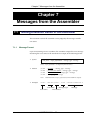
Chapter 7 Messages from the Assembler
7.1
7.2
49
Getting Execution Result of the Assembler ........................................................... 80
7.1.1
Message Format ..................................................................................................... 80
7.1.2
Message Types ...................................................................................................... 81
7.1.3
Exit Status ............................................................................................................... 81
Message Lists ........................................................................................................ 82
7.2.1
Warning Messages ................................................................................................. 82
7.2.2
Error Messages ...................................................................................................... 84
7.2.3
Fatal Error Messages ............................................................................................. 94
Assembler - v
80
Contents
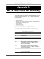
Appendix A M32R Instruction Set Summary
A.1
95
M32R Instruction Set ............................................................................................. 97
■ Load/Store Instructions ........................................................................ 97
■ Transfer Instructions ............................................................................ 98
■ Arithmetic/logic Operation Instructions ................................................ 98
■ Branch Instructions ............................................................................ 100
■ EIT-related Instructions ...................................................................... 100
■ DSP Function Instructions ................................................................. 101
A.2
Extended Instructions of M32Rx/D Series ........................................................... 102
A.2.1
New Extended Instructions of M32Rx ................................................................... 102
■ New Extended Instructions of M32Rx ................................................ 102
A.2.2
Specification Extended Instructions of M32Rx ..................................................... 103
■ Specification Extended Instructions of M32Rx .................................. 103
Appendix B Pseudo-instruction Reference
104
Appendix C Macro-instruction Reference
124
Appendix D Assembler List File
140
Appendix E M32R/ECU#5 Extension Instruction
148
E.1
Option designation ............................................................................................... 148
E.2
M32R/ECU#5 extension instruction ..................................................................... 149
Appendix F Floating Point Compatible Function
F.1
F.2
F.3
Floating-point constant ........................................................................................ 150
F.1.1
Description format ................................................................................................. 150
F.1.2
Available place ...................................................................................................... 151
F.1.3
Compatibility ......................................................................................................... 151
F.1.4
Non-normalized numeral handling ........................................................................ 151
Extended pseudo instruction ............................................................................... 152
F.2.1
Format .................................................................................................................. 152
F.2.2
Function of pseudo instruction .............................................................................. 152
F.2.3
Common items ...................................................................................................... 153
Utilization of floating point in general instruction line ........................................... 153
Assembler - vi
150
Contents
Appendix G Restrictions on Usage
■ How to get files that is not included the debug-informatio ............................................ 154
■ Cautions on using the base register function with standard library for C ...................... 155
■ Avoiding the integral zero-division problem of M32R/ECU series ................................. 155
■ On indirect calling a function that has variable arguments ............................................ 157
■ Data definition within the code section .......................................................................... 157
■ Use of preprocessor variables inside a macro body ...................................................... 157
■ About compiling the functions of 500 or more lines ....................................................... 158
■ Precautions about changing C Calling Convention ....................................................... 158
Assembler - vii
154
Contents
Part 2
Linker
lnk32R
Chapter 1 Overview of the Linker lnk32R
1.1
Overview .................................................................................................................. 1
1.2
Functions ................................................................................................................. 1
1.3
Compatibility with an old version ............................................................................. 2
1.3.1
About inputting old CC32R's object (V.2.10 Release 1 or older) to new linker ......... 2
1.3.2
About error processing of lnk32R ............................................................................. 3
1.3.3
About error processing of lnk32R(CC32R V.4.30 Release 1 or subsequent one) .... 5
Chapter 2 Invoke the Linker
2.1
1
6
How to Invoke the Linker ......................................................................................... 6
2.1.1
Invoking Procedure ................................................................................................... 6
2.1.2
Setting Environment Variables ................................................................................. 6
2.1.3
Command Line Format ............................................................................................. 7
2.1.3.1
Command Line Rules ............................................................................................ 7
2.1.3.2
Invocation Using Command File ............................................................................ 8
2.1.4
Input File Conditions ................................................................................................. 9
2.1.5
Output File Conditions .............................................................................................. 9
2.1.6
Output File Naming ................................................................................................... 9
2.2
Command Options ................................................................................................. 10
2.3
Command Line Examples ...................................................................................... 14
Chapter 3 Creating load modules
3.1
I
15
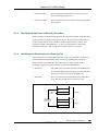
Creating absolute load modules ............................................................................ 15
3.1.1
Linking Object modules (Linking Sections) ............................................................ 15
3.1.2
Locating Sections ................................................................................................... 15
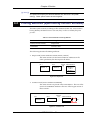
3.2
Creating Relocatable Load Module ....................................................................... 16
3.3
Linking Library Files ............................................................................................... 16
Chapter 4 Section
18
4.1
Section Types ........................................................................................................ 18
4.2
Section Definitions (Section Information) ............................................................... 18
4.3
Link Functions ........................................................................................................ 19
4.3.1
Automatic Link of Sections ..................................................................................... 19
4.3.2
Specifying Linking Order of Sections ...................................................................... 19
4.3.3
Specifying Location Address of Section ................................................................. 20
Assembler - viii
Contents
4.4
Linking Methods (Specified by section attribute) ................................................... 21
4.5
Locating Methods (Specified by location attribute) ................................................ 22
Chapter 5 For ROM Writing
5.1
5.2
Processing Sections for ROM Writing ................................................................... 23
5.1.1
Specifying Location Area of Section (by the linker) ................................................ 23
5.1.2
Specifying Output Area of Data (by the linker) ....................................................... 24
5.1.3
Initializing the Data Sections (in Start-up File) ........................................................ 24
Committing Applications to ROM ........................................................................... 25
5.2.1
Initial Data Elimination ............................................................................................ 25
5.2.2
Initial Data Extraction .............................................................................................. 26
5.2.3
Reserved Labels Generation .................................................................................. 27
Chapter 6 Messages from the Linker
6.1
6.2
23
Getting Execution Result of the Linker .................................................................. 29
6.1.1
Message Format ..................................................................................................... 29
6.1.2
Message Types ...................................................................................................... 29
6.1.3
Exit Status ............................................................................................................... 30
Message Lists ........................................................................................................ 31
6.2.1
Warning Messages ................................................................................................. 31
6.2.2
Error Messages ...................................................................................................... 31
6.2.3
Fatal Error Messages ............................................................................................. 34
Assembler - ix
29
Contents
Part 3
Map Generator map32R
Chapter 1 Overview of the Map Generator map32R
1.1
1
Overview .................................................................................................................. 1
Chapter 2 Invoke the Map Generator
2.1
I
2
How to Invoke the Map Generator ........................................................................... 2
2.1.1
Invoking Procedure ................................................................................................... 2
2.1.2
Setting Environment Variables ................................................................................. 2
2.1.3
Command Line Format ............................................................................................. 3
2.1.4
Input File Conditions ................................................................................................. 4
2.1.5
Output File Naming ................................................................................................... 4
2.2
Command Options ................................................................................................... 5
2.3
Command Line Examples ........................................................................................ 7
Chapter 3 Link Map File
3.1
Contents of Link Map File ........................................................................................ 8
3.2
Contents of Map List ................................................................................................ 9
3.3
Contents of Global Symbol List ............................................................................. 10
3.3
About extended output forms of map32R .............................................................. 11
8
Chapter 4 The Access Control File Generation Function 14
4.1
Details of the Access Control File Generation Function ........................................ 14
4.2
Example of Using the Access Control File Generation Function ........................... 15
4.3
Notes ..................................................................................................................... 16
Chapter 5 Csv symbol map file output
5.1
5.2
5.3
Details of the Csv symbol map file ......................................................................... 17
5.1.1
Generation of the csv symbol map file .................................................................... 17
5.1.2
Form of the csv symbol map file ............................................................................. 17
Example of output the Csv symbol map file ........................................................... 18
5.2.1
Example of “-c” option ............................................................................................. 18
5.2.2
Example of “-c16” option ......................................................................................... 19
Notes ..................................................................................................................... 19
Assembler - x
17
Contents
Chapter 6 Messages from the Map Generator
6.1
6.2
Getting Execution Result of the Map Generator .................................................... 20
6.1.1
Message Format ..................................................................................................... 20
6.1.2
Message Types ...................................................................................................... 20
6.1.3
Exit Status ............................................................................................................... 21
Message Lists ........................................................................................................ 21
6.2.1
Error Messages ...................................................................................................... 21
6.2.2
Fatal Error Messages ............................................................................................. 22
Assembler - xi
20
Contents
Part 4
Librarian lib32R
Chapter 1 Overview of the Librarian lib32R
1.1
Overview .................................................................................................................. 1
1.2
Functions ................................................................................................................. 1
Chapter 2 Invoke the Librarian
2.1
2.1.1
Invoking Procedure ................................................................................................... 3
2.1.2
Setting Environment Variables ................................................................................. 3
2.1.3
Command Line Format ............................................................................................. 4
2.1.3.1
Command Line Rules ............................................................................................ 4
2.1.3.2
Invocation Using Command File ............................................................................ 5
2.1.4
Input File Conditions ................................................................................................. 6
2.1.5
Generated Library Conditions ................................................................................... 6
2.1.6
Output File Naming ................................................................................................... 6
Command Options ................................................................................................... 7
2.3
Command Line Examples ........................................................................................ 9
Chapter 3 Outputs from the Librarian
3.1
Library .................................................................................................................... 11
3.2
Librarian List .......................................................................................................... 11
3.3
Library Information ................................................................................................. 12
Chapter 4 Messages from the Librarian
4.2
1
3
How to Invoke the Librarian ..................................................................................... 3
2.2
4.1
I
Getting Execution Result of the Librarian .............................................................. 14
4.1.1
Message Format ..................................................................................................... 14
4.1.2
Message Types ...................................................................................................... 15
4.1.3
Exit Status ............................................................................................................... 15
Message Lists ........................................................................................................ 16
4.2.1
Warning Messages ................................................................................................. 16
4.2.2
Error Messages ...................................................................................................... 16
4.2.3
Fatal Error Messages ............................................................................................. 18
Assembler - xii
11
14
Contents
Part 5
Load Module Converter lmc32R I
Chapter 1 Overview of the Load Module Converter lmc32R
1.1
Overview .................................................................................................................. 1
1.2
Functions ................................................................................................................. 1
Chapter 2 Invoke the Load Module Converter
2.1
2.2
1
2
How to Invoke the Load Module Converter ............................................................. 2
2.1.1
Invoking Procedure ................................................................................................... 2
2.1.2
Setting Environment Variables ................................................................................. 2
2.1.3
Command Line Format ............................................................................................. 3
2.1.4
Input File Conditions ................................................................................................. 3
2.1.5
Output File Naming ................................................................................................... 4
Command Options ................................................................................................... 5
Chapter 3 Usage and Command Line Examples
3.1
Converting into Divided S-format Files (Object Division Function) ......................... 7
3.2
Converting a part of the Load Module into S-format (Convert Area Select Function) .... 8
3.3
Changing Addresses of Load Module(Change Load Address Function) ................ 9
Chapter 4 S-format
7
10
4.1
Motorola S-format File Structure ............................................................................ 10
4.2
Record Structure .................................................................................................... 11
4.2.1
Header Record ....................................................................................................... 11
4.2.2
Data Record ............................................................................................................ 11
4.2.3
End Record ............................................................................................................. 13
Assembler - xiii
Preface
Preface
M3T-CC32R(abbreviated as CC32R) is a cross tool kit which supports software
development for the Renesas M32R family of 32-bit RISC architecture
microcomputers. It provides many functions suitable for development of
embedded systems for the M32R family. The CC32R manual set provides
information for programming by use of CC32R, targeting an M32R system.
Audience
The CC32R manual set assumes that the readers are developers programming
for the M32R system using the C or assembly language. Accordingly, it also
assumes that the readers are familiar with programming languages (C or
assembly) and their development environment (a host machine and its
operating system etc.), and have basic knowledge of the target M32R systems.
References
A manual related to development for the M32R family is :
• M32R Family User's Manual
• M32R Family Software Manual
Refer to the WWW site of the "Renesas Microcomputers" for the details of the
information about development of M32R Family.
The URL is : http://www.renesas.com/
For details about the ANSI-C language, refer to :
• ANSI/ISO 9899-1990 American National Standard for Programming
Languages - C (American National Standards Institute, Inc. )
AS32R MANUAL - xiv
Preface
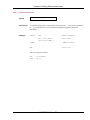
Conventions
The CC32R manual set uses the following conventions :
• Symbols
Symbol
Meaning
Italics
Represents a generic description that should be
replaced with a specific.
a |b
Represents alternative items. a|b represents either a
or b.
[]
Encloses optional elements that can be included or
omitted.
...
Indicates to repeat the preceding item zero or more
times.
:
Represents omission of a or more lines.
<RET>
Represents to enter the return key.
• Terms(1/2)
Term
Meaning
ANSI-C
American National Standard for Programming
Languages-C (ANSI/ISO 9899-1990)
Assembler (as32R)
The assembler in CC32R.
Assembly program
A program written in the assembly language.
CC32R
The cross tool kit for an M32R system.
C compiler (cc32R)
The C compiler in CC32R.
C program
A program written in the C language.
CRx
Any control register of M32R.
C standard library
The CC32R-supplied ANSI-C conforming library.
Default
A value (or values) or the process provided
automatically if there is none specified by the user.
EWS
An engineering work station.
Librarian (lib32R)
The librarian in CC32R.
Library (file)
A C library file for an M32R system. It is an output
file from lib32R.
Linker (lnk32R)
The linker in CC32R.
AS32R MANUAL - xv
Preface
• Terms(2/2)
Term
Meaning
Link map
A list have information on sections and global
symbols in an object module or a load module. It is
generated by map32R.
Load module (file)
A linked object module, which is an executable file for
an M32R system. It is an output file from lnk32R or
lmc32R.
Load module converter (lmc32R) The load module converter in CC32R.
Local variable
This variable is only effective in a function.
M32R
M32Rx
A Renesas 32-bit RISC architecture microcomputer.
M32R system
A system using the M32R.
Map generator (map32R)
The map generator in CC32R.
Object module (file)
An object file which is translated from the C or
assembly code into the object code of machine
instructions for M32R. It is an output file from the C
compiler or the assembler.
OS
An operating system.
Release notes
The document related to the release of the CC32R in a
CC32R package (Please read it at first.).
Return value
A function value returned as an operation result from
a called function to a calling function.
Rx
Any general register of M32R.
Source file
A text file written source code in the C language or the
assembly language.
Space (character)
A blank which is entered by the space key or the tab
key.
User library
A library file made by a user using the librarian.
Windows
Any of Microsoft Windows3.1 or Microsoft
Windows95.
AS32R MANUAL - xvi
Preface
Organization of This Manual
This manual consists of :
■ Part 1
Assembler as32R
Chapter 1
Chapter 2
Chapter 3
Chapter 4
Chapter 5
Chapter 6
Chapter 7
AppendixA
Appendix B
Appendix C
Appendix D
Appendix E
Appendix F
Appendix G
■ Part 2
Linker lnk32R
Chapter 1
Chapter 2
Chapter 3
Chapter 4
Chapter 5
Chapter 6
■ Part 3
Overview of the Map Generator map32R
Invoke the Map Generator
Link Map File
The Access Control File Generation Function
Csv symbol map file output
Messages from the Map Generator
Librarian lib32R
Chapter 1
Chapter 2
Chapter 3
Chapter 4
■ Part 5
Overview of the Linker lnk32R
Invoke the Linker
Creating load modules
Section
For ROM Writing
Messages from the Linker
Map Generator map32R
Chapter 1
Chapter 2
Chapter 3
Chapter 4
Chapter 5
Chapter 6
■ Part 4
Overview of as32R
Invoking the Assembler
Assembly Language Specifications
Coding General Instructions
Coding Pseudo-instructions
Coding Macro-instructions
Messages from the Assembler
M32R Instruction Set Summary
Pseudo-instruction Reference
Macro-instruction Reference
Assembler List File
M32R/ECU#5 Extension Instruction
Floating Point Compatible Function
Restrictions on Usage
Overview of the Librarian lib32R
Invoke the Librarian
Outputs from the Librarian
Messages from the Librarian
Load Module Converter lmc32R
Chapter 1
Chapter 2
Chapter 3
Chapter 4
Chapter 5
Overview of the Load Module Converter lmc32R
Invoke the Load Module Converter
Usage and Command Line Examples
S-format
Messages from the Load Module Converter
AS32R MANUAL - xvii
Part 1
Assembler as32R
Chapter 1 Overview of as32R
Chapter 1
Overview of as32R
1.1
1.1.1
About the Assembler as32R
as32R Functions
The as32R is the assembler contained in the cross tool kit M3T-CC32R, and has
the following functions :
• Generates an object module by assembling each assembly source file.
• as32R calls :
• a032R (macro processor)
• a132R (assemble processor)
• alis32R (list processor)
To obtain load modules from the object modules that the assembler generates,
use the linker (lnk32R) contained in the cross tool kit M3T-CC32R.
1.1.2
as32R Features
The assembler provides the following features :
• Optimizing the operand size
Chooses the shortest-length instruction if an instruction can have
two or more lengths, depending on the operand size.
• Automatic adjusting the instruction position
Automatically adjusts the position of an instruction that must be
located at a word boundary.
• Numerical correction for dealing with a 32-bit immediate data
Provides a means to carry out numerical correction that enables
you to easily describe a 32-bit constant or address.
• Macro processing
Handles macros. You can define macros by using macroinstructions of the assembler and call the macros.
AS32R MANUAL - 1
Chapter 2 Invoking the Assembler
Chapter 2
Invoking the Assembler
2.1
2.1.1
How to Invoke the Assembler
Invoking Procedure
To invoke the assembler, set environment variables (see 2.1.2), then enter the
“as32R” command in line with the applicable rule to execute it (see 2.1.3).
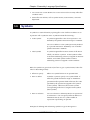
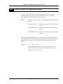
2.1.2
Setting Environment Variables
Set the valid directories for the environment variables M32RBIN, M32RINC,
M32RLIB, and M32RTMP. For the setting procedure, refer to ““M3T-CC32R
Cross Tool-Kit V.x.xx Release x Release Note“. If you do not set them, the
directories (see Table 2.1) are selected automatically.
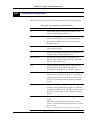
Table 2.1 Environment Variables
Environment variable
Default
M32RBIN
/usr/local/M32R/bin
M32RINC
/usr/local/M32R/include
M32RLIB
/usr/local/M32R/lib
M32RTMP
/tmp
AS32R MANUAL - 2
Chapter 2 Invoking the Assembler
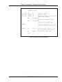
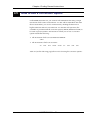
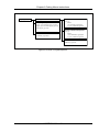
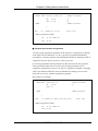
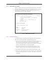
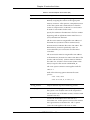
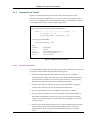
2.1.3
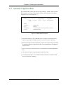
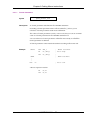
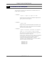
Command Line Syntax and Rules
The command line syntax and rules for the command, “as32R”, which invokes
the assembler are as follows (For details on the command options and input/
output files, see 2.1.4 through 2.2. ) :
as32R
[-g] [-V] [-w] [-o output_filename] [-l list_filename]
[-I dir] [-D[= def]] [-m32r] [-m32rx] [input_filename]
<RET>
where :
• Without [ ]
: Indispensable
• In [ ]
: Optional
• Prefixed by -
: A command option ( and its parameter(s) ) (See 2.2.)
• <RET>
: Enter the return key
Figure 2.1 as32R Command Line Syntax
• Each of the items (i.e., the command name, an option, an input file name)
must be separated from adjacent items by at least one space character.
• Between an option and its parameter(s), one or more spaces may be inserted.
If conflicting options are specified in the same command line, the rightmost
option is used.
• You can enter up to 255 characters in a command line (excluding the Return
key).
• input_filename represents specifying one input file name.
• To link object modules, use the linker lnk32R contained in CC32R. (as32R
have no functions of linking .)
AS32R MANUAL - 3
Chapter 2 Invoking the Assembler
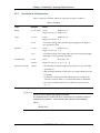
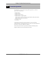
2.1.4
Input File Conditions
Conditions for input files to be assembled are given in Table 2.2. You cannot
assemble files that don’t satisfy these conditions.
Table 2.2 Input File Conditions
Item
Condition
A file that can be input
A source file written in assembly language.
Its file extension, “.ms” or otherwise, is
allowed.
Instructions described
You must write an assembly-language source
file to input using only the general instructions
of M32R instructions, pseudo-instructions, and
macro-instructions of the assembler.
Maximum length of a name
Maximum number of names
Module name
: Up to 206 characters
Symbol name
: Up to 243 characters
Section name
: Up to 243 characters
Preprocessor variable
: Up to 32 characters
Macro name
: Up to 32 characters
Up to 65535 names can be processed at a time.
The number may be limited by the capacity of
development environment system memory.
2.1.5
Output File Naming
The output file name becomes what you specify under -o output_filename. If
you omit this, by default, the file is named as given in Table 2.3 .
Table 2.3 Output File Name (Default)
File name
Description
file.mo
An object module file output as a result of assembling.
A file name in which the extension of the source file name is
replaced by “.mo”. (If a source file has no extension, “.mo” is
suffixed to the source file name.)
2.1.6
List File Naming
The list file name becomes what you specify under -l list_filename .
AS32R MANUAL - 4
Chapter 2 Invoking the Assembler
2.2
2.2.1
Command Options
Command Options
Table 2.4 shows the functions of the command options available for the as32R
command that are valid for starting the assembler.
Table 2.4 Command Options for the Assembler(1/2)
Option
Description
-g
Outputs information necessary for debugging
(debugging information) to the object module file.
-I dir
Adds dir to the directory under which a header file is
to be searched.
The header file search is performed in the order
shown :
(1) Within the directory containing the file in which
the .INCLUDE instruction is written.
(2) Within the directory specified by this option.
(3) Within the directory for which the environment
variable M32RINC is set ( If not set, in the order
/usr/local/M32R/include.).
This option can be specified more than once (up to 10)
in a command line, as in -I dir1 -I dir2. In this case,
header files are searched for in the directory shown
above (1), dir1, dir2, and the directory shown above
(3), in that order. Spaces between "-I" and "dir" are
optional.
-l list_filename
Creates a list file named “list_filename”. Spaces
between “-l” and “list_filename” are optional. If this
option is not specified, a list file is not created (see
Appendix D, “Assemble list file” for a list file).
-o output_filename
Generates an object module named “output_filename”.
('o' is a lower case)
Omitting this option generates an object module using
a file name resulting from changing the extension of
input file name to “.mo”.
If an input file name has no its extension, the output
file name is named by resulting from suffixing “.mo”
to the input file name.
AS32R MANUAL - 5
Chapter 2 Invoking the Assembler
Table 2.4 Command Options for the Assembler(2/2)
Option
Description
-V (upper case)
Outputs the invoking message to the standard error
output. The other options are ignored. No processing
actually takes place.
-w
Suppresses warning messages.
-D name[=def]
Associates the character variable name with the
character sequence def. Assumes that name=1 if “=def”
is omitted. This option has the same function as
macro-instruction .ASSIGNC.
You may omit a space character between -D and
name.
-m32r
Assembles M32R instructions. Parallel instructions
and the instructions inherent in M32Rx cannot be
processed. If no option is used in the assembler that
specifies a specific CPU, the assembler by default
assumes this option as it assembles instructions.
-m32rx
Assembles instructions that have been added to or
changed in M32Rx, in addition to M32R instructions.
Furthermore, parallel instructions of M32Rx can be
processed. Accumulator specification in MULHI or
other instructions to specify an accumulator can be
omitted. (When no accumulator is specified, the
assembler by default assumes A0 as it processes
instructions.)
Also refer to Section 2.2.2 for more information about
his option.
-m32re5
This option makes M32R/ECU#5 extension
instruction valid.Also, the floating-point constant,
which is not normalized,is reduced to "0.0".
-zdiv
For avoiding the integral zero-division problem of
M32R/ECU series, to insert NOP instructions each
after the all of this DIV-instructions.
AS32R MANUAL - 6
Chapter 2 Invoking the Assembler
2.2.2
About M32Rx Instructions
The assembler supports parallel instructions of M32Rx. For details about
parallel instructions of M32Rx, refer to "M32Rx Software Manual."
• Precautions to be observed when writing parallel instructions
O Instructions that can be written in parallel
Instructions that can be written in parallel are limited to combinations
of instruction categories. (Refer to “Chapter 4 M32Rx Instructions”
and "M32Rx Software Manual.")
If any other instruction statement is written, the assembler outputs the
error message shown below and stops processing the instructions that
follow.
(Error message)
a132R: “xxx”, line 1: error: invalid parallel category
O About operand interference
If when executing parallel instructions the same resource is
simultaneously accessed for write (operand interference), assembler
operation in M32Rx is not guaranteed. The same dependency
relationship as this operand interference also applies to control
registers such as PSW and CBR that include the condition bit (C), in
which case assembler operation is not guaranteed either.
The assembler has a facility to check for operand interference. If an
operand interference is committed, the assembler outputs an error
message like the one shown below:
(Error message)
a132R: “xxx”, line 1: error: write to the same destination register
For details about operand interference, refer to the "M32Rx Software
Manual."
AS32R MANUAL - 7
Chapter 3 Assembly Language Specifications
Chapter 3
Assembly Language Specifications
This chapter describes the basic specifications of the assembly language for
M32R which is processed by the assembler. “Source” as used in this chapter
refers to a source program written in assembly language.
3.1
Line Format
A source program written in assembly language is made on a line-by-line basis
(you write one instruction in one line). The range of a line is defined as follows:
• From the beginning of a source file to the first new-line character.
• From the character immediately subsequent to a new-line character either to
the next new-line character or to the end of a source file.
The range of a new-line character finishes one line. The number of characters in
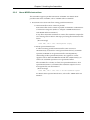
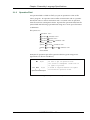
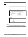
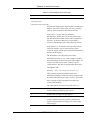
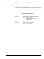
a line is unlimited. A line is made up of four fields given in Figure 3.1. A field
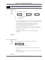
may be omitted if it is not necessary.
Symbol
Operation
Operands
Comment
LABEL:
LDI
R0,#0
; comment
Symbol
Field
Operation
Field
Operand
Field
Comment
Field
• Symbol field
A field in which you write a symbol.
• Operation field
A field in which you write an operation.
• Operand field
A field in which you write instruction operands.
• Comment field
A field in which you write comments.
Figure 3.1 One Line of a Source Program
AS32R MANUAL - 8
<CR>
Chapter 3 Assembly Language Specifications
One or more space characters are required between the symbol field and the
operation field and between the operation field and the operand field.
Section 3.1.1 and subsequent sections explain the individual fields. The
following notation is used :
: One or more optional space characters
(you enter space character(s) or tab character(s))
: One or more required space characters
(you enter space character(s) or tab character(s))
<CR>
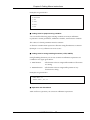
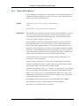
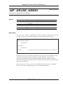
3.1.1
: A new-line character
Symbol Field
A symbol field is a field in which you write a symbol or a preprocessing
variable for macro-instructions in a line of a source program (see 3.6
“Symbols”).
Usually you put a symbol from the first column, but you can write it from the
second or subsequent column. Be careful about the following in writing a
symbol :
• To write a symbol from the first column :
The syntax are :
symbol;comment
symbol
;comment<CR>
symbol<CR>
symbol;comment<CR>
↑
first column
Either a field extending from the first column to a colon (:) or a
field extending from the first column to the column immediately
before a space, new-line character, or semicolon (;) forms a
symbol field. A string in the field turns to a symbol.
You can omit a colon (:) only when you put a symbol from the
first column.
What you write from the first column is recognized as a symbol
even if it matches a reserved word (see 3.4 “Reserved Words”).
AS32R MANUAL - 9
Chapter 3 Assembly Language Specifications
• To write a symbol from the second or subsequent column :
The syntax are :
symbol:;comment<CR>
symbol
;comment<CR>
↑
first column
This is to enter blank characters at the beginning of a line (from
the first column to the column immediately before the symbol's
first character). In this instance, be sure to place a colon (:) at the
end of the symbol.
Columns from the first column to the colon (:) form a symbol
field. The part excluding the colon (:) and the space characters
forms the symbol.
If the symbol you put from the second or subsequent column
matches a reserved word, an error occurs.
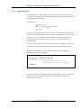
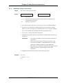
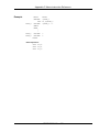
Examples of writing symbols in the symbol field are given in Figure 3.2.
(Symbols are shown in boldface.)
first column
↓
SYM1
LDI
SYM0: .EQU
SYM2:
R1,#0
; Defines a label symbol.
10
; Defines a value symbol.
; colon (:) is required at the end
; if you put a symbol from
; the second or subsequent column.
Figure 3.2 Writing Symbols in the Symbol Field
AS32R MANUAL - 10
Chapter 3 Assembly Language Specifications
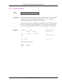
3.1.2
Operation Field
An operation field is a field in which you put an operation in a line of the
source program. An operation can be either an instruction code or a pseudoinstruction code or a macro-instruction code. You must write an operation
from the second or subsequent column. Separate the operation field from the
symbol field and following operand fields using one or more space characters
as delimiters.
The syntax are :
operation <CR>
operation ;comment <CR>
operation
operand <CR>
operation
operand ;comment <CR>
symbol: operation
symbol: operation ;comment <CR>
symbol: operation operand ;comment <CR>
↑
first column
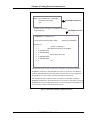
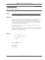
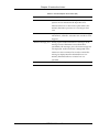
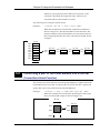
Examples of operations put in the operation field are given in Figure 3.3.
(Operations are shown in boldface.)
MV
R0,R1
; Be sure to put an operation from
; the second or subsequent column even if
; no symbol is present.
SYM1 LDI
↑
R1,#0
↑
; A blank is required between the symbol
; field and the operation field.
Space characters input
Figure 3.3 Operations Put in the Operation Field
AS32R MANUAL - 11
Chapter 3 Assembly Language Specifications
3.1.3
Operand Field
An operand field is a field in which you specify an operand or operands in a
line of a source program.
Operands for an operand field are :
• operands for general instructions
• operands for pseudo-instructions
• correction options (HIGH, SHIGH, LOW) for general instructions
The syntax are :
operation
operand<CR>
operation
operand1,operand2<CR>
operation
operand ;comment <CR>
Symbol: operation
operand ;comment <CR>
↑
first column
To specify two or more operands, delimit them with a comma (,). Separate the
operation field from the operand field with one or more spaces. No operand
field is present in a line comprising an instruction that requires no operand.
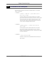
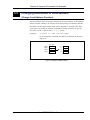
Examples of operands put in the operand field are given in Figure 3.4
(Operands are shown in boldface.).
Space characters input
↓
SYM1
R1,#0 ; Delimit two or more operands with
LDI
; a comma (,). A blank is required between
; the operation field and the operand field.
NOP
; There can be an instruction line in which
; no operand field is present.
SETH
R0,#HIGH(H'ffffffff)
; A correction option (underlined) is
; specified in the operand field.
Figure 3.4 Operands Put in the Operand Field
AS32R MANUAL - 12
Chapter 3 Assembly Language Specifications
3.1.4
Comment Field
A comment field is a field in which you write a comment in a line of a source
program. A comment is an optional description of user's information and is not
to be subjected to assembling.
The syntax are :
;comment <CR>
expect comment field ;comment <CR>
↑
first column
Be sure to start a comment with a semicolon (;). The assembler recognizes the
characters from the semicolon (;) to the column immediately preceding the next
new-line character as a comment field, but does not regard a semicolon (;)
enclosed in a pair of double quotation marks (") as the first character of a
comment field.
You can write a comment in any line (or can omit it as intended). You can use
any character of the applicable character set except the new-line character.
Examples of comments put in the comment field are given in Figure 3.5
(Comments are shown in boldface.).
;Loads 10 into R0
;LDI R0,#10 ;Loads 10 into R0
LDI
R0,#10
;placing a semicolon in the first
;column makes the whole line a comment.
;comment
Figure 3.5 Comments Put in the Comment Field
In a macro definition with the macro-instruction .MACRO ~.END, a comment,
which will not be expanded, can be put. See Chapter 6 “Coding Macro
Instructions” for details.
AS32R MANUAL - 13
Chapter 3 Assembly Language Specifications
3.2
Line Types
A source program consists of the following types of lines :
• General instruction line
Specifies an M32R instruction. The assembler
translates this line into object code that target on the
M32R family.
• Pseudo-instruction line
Specifies a pseudo-instruction for the assembler. This
line gives the assembler directive(s) involved in
assembly.
• Macro-instruction line
define a macro by use of macro-instruction.
• Comment line
Consists of comment(s) only. This line is not
processed by the assembler.
• Blank line
Specifies nothing (lines containing optional spaces
and a new-line character only). This line is not
processed by the assembler similarly to a comment
line.
• Symbol line
Specifies a symbol only. This line consists of only a
symbol field or consists of a symbol field and a
comment field. The specified symbol is assigned the
location counter of that line.
AS32R MANUAL - 14
Chapter 3 Assembly Language Specifications
3.3
Character Set
Table 3.1 gives characters that can be used in assembly language source
programs.
Table 3.1 Character Set (1/2)
Class
Character(s)
ASCII Code
Name (Note)
Alphabetic letters
A-Z
H'41 - H'5A
Uppercase alphabetic letters
a-z
H'61 - H'7A
Lowercase alphabetic letters
Digits
0-9
H'30 - H'39
Digits
Alphanumerics
Nomenclature for combination of alphabetic letters and digits
Special characters
"
H'22
Double quotation
#
H'23
Number sign
$
H'24
Dollar sign (may be used as a symbol)
&
H'26
Ampersand
'
H'27
Single quotation
(
H'28
Left parenthesis
)
H'29
Right parenthesis
*
H'2A
Asterisk
+
H'2B
Plus
,
H'2C
Comma
-
H'2D
Minus
.
H'2E
Period
/
H'2F
Slash
:
H'3A
Colon
;
H'3B
Semicolon
<
H'3C
Less than
=
H'3D
Equal
>
H'3E
Greater than
@
H'40
At mark
\
H'5C
Yen or backslash
_
H'5F
Underscore
|
H'7C
Logical disjunction (Vertical line)
~
H'7E
Tilde
AS32R MANUAL - 15
Chapter 3 Assembly Language Specifications
Table 3.1 Character Set (2/2)
Class
Character
ASCII Code
Name (Note)
Blank character
(SP)
H'20
Space
(HT)
H'09
Horizontal tab
(CR)
H'0D
Carriage return
(LF)
H'0A
Line feed
(FF)
H'0C
Form feed
New-line character
Others
Characters other than the above, if available on your computer, may be used in
comment only.
3.4
Reserved Words
The assembler interprets the following identifiers as reserved words. No
distinction is drawn between uppercase and lowercase letters :
• Register names
• Special symbols
• Mnemonics
3.4.1
Register Names
A register name is a reserved word that stands for a register of the M32R
family, and includes the following :
• General register names
Rx (R0 to R15), SP
Note) R15 (stack pointer) can be specified by either R15 or SP.
• Control register names
CRx (CR0 to CR15), PSW, CBR, SPI, SPU
Note) These are used only for the operand of the general
instructions MVFC and MVTC.
• Accumulator names (Case of M32Rx )
A0, A1
Note) The accumulators are also used for the multiplication
instruction "MUL". Therefore take note that when this
instruction is executed, the values in the accumulators, A0
and A1 are erased.
Note) These are used only for the operand of the specification
Extended Instructions of M32Rx MVTACHI, MVTACLO,
MVFACHI, MVFACLO and MVFACMI.
AS32R MANUAL - 16
Chapter 3 Assembly Language Specifications
3.4.2
Special Symbols
A special symbol is a reserved symbol specified by an operand, and includes
the following :
SIZEOF
3.4.3
SHIGH
HIGH
LOW
Mnemonics
A mnemonic is a reserved word that represents either an instruction (e.g., LD,
.PROGRAM).
• Mnemonics for general instructions :
LD
ST
MV
ADD etc.
• Mnemonics for pseudo-instructions :
.ALIGN
.PROGRAM .SECTION
.END
.EXPORT
.IMPORT
.GLOBAL
.EQU
.ASSIGN
.DATA
.DATAB
.SDATA
.SDATAB
.RES
• Mnemonics for macro-instructions :
.AIF
.AELSE
.AENDI
.AREPEAT
.AENDR
.ASSINGA
.ASSIGNC
.AWHILE
.AENDW
.EXITM
.INCLUDE
.INSTR
.LEN
.SUBSTR
.MACRO
.ENDM
AS32R MANUAL - 17
Chapter 3 Assembly Language Specifications
3.5
Names
Names are character strings that represent the following :
• Names the user can define
• Module name ( It can be defined by the .PROGRAM pseudoinstruction. A reserved word is available.)
• Symbol name ( A reserved word is not available. See 3.6
“Symbols”.)
• Section name ( It can be defined by the .SECTION pseudoinstruction. A reserved word is not available.)
• Preprocessing variable
• Macro name
• Names the user cannot define
Reserved words (register names, special symbols, mnemonics)
Rules for names are given below :
• Characters you can use for the leading character
One of alphabetic letters, dollar sign ($), and underscore (_).
You cannot use a digit for the leading character.
• Characters you can use for the second and subsequent characters
One of alphanumeric characters, dollar sign ($), and
underscore ( _ )
• The number of characters you can use in a name
• Module name
: 206 characters
• Symbol name
: 243 characters
• Section name
: 243 characters
• Preprocessing name : 32 characters
• Macro name
: 32 characters
• Distinction between uppercase and lowercase letters
Distinction is made for names the user can define.
No distinction is made for names the user cannot define.
You define a name according to the preceding rules. Be careful about the
following in that instance :
AS32R MANUAL - 18
Chapter 3 Assembly Language Specifications
• You cannot use a name identical to a reserved word for an entity other than
a module name.
• Names the user defines, such as symbol names, section names, cannot be
duplicated.
3.6
Symbols
A symbol is a result effected by replacing the value of either an address or an
expression with a symbolic name. Symbols include the following :
• Value symbol
A symbol assigned the value of an expression. It is
defined by the pseudo-instruction .EQU or .ASSIGN.
You can re-define a value symbol previously defined
by a pseudo-instruction .ASSIGN by use of another
pseudo-instruction .ASSIGN.
• Label symbol
A symbol assigned the location counter of the line in
which you declare a symbol. A label symbol within
an absolute addressing section is assigned an absolute
address, and a label symbol within a relative
addressing section is assigned a relative address.
Rules for symbols are given below (For how to give a symbol name, follow the
rules for describing names) :
• Where to specify
Either in a symbol field or in an operand field.
• How to define
To define a symbol, specify it in a symbol field. If
either the pseudo-instruction .EQU or .ASSIGN is
presented in the operation field in the line, the value
specified by the operand is assigned to the symbol
(value symbol). Otherwise, the location counter
corresponding to the line is assigned to the symbol
(label symbol).
• How to reference
You can reference a defined symbol in an operand of
an instruction. You can specify either an address or
immediate data by use of a symbol within an
expression representing an operand.
Examples of defining and referencing symbols are given in Figure 3.6.
AS32R MANUAL - 19
Chapter 3 Assembly Language Specifications
.SECTION
program
;
VAL_SYM0: .EQU
10
; Defining a symbol
VAL_SYM1: .ASSIGN
20
; Defining a symbol
VAL_SYM1: .ASSIGN
30
; Re-defining a symbol that has been
; defined under .ASSIGN
SETH
R0,#VAL_SYM0
; Referencing a defining symbol
SETH
R1,#VAL_SYM1
; Referencing a defining symbol
;
LABEL0:
; Defining a label symbol in a line
; in which no instruction is present
;
LABEL1:
MV
R5,R0
; Defining a label symbol in a line
; in which instruction is present
BL
LABEL0
; Referencing a label symbol
;
.END
Figure 3.6 Defining and Referencing Symbols
AS32R MANUAL - 20
Chapter 3 Assembly Language Specifications
3.7
Preprocessing Variables
Preprocessing variables available as operands of macro-instructions.
Otherwise, unavailable. The two kinds of preprocessing variable are
“arithmetic variable” and “character variable” :
• Arithmetic variable
A variable assigned to the value of an arithmetic expression
specified as an operand of the macro-instruction .ASSIGNA.
For details about arithmetic expressions, refer to Chapter 6.
• Character variable
A variable assigned to the value of a character expression
specified as an operand of the macro-instruction .ASSIGNC.
For details about character expressions, refer to Chapter 6.
The following example shows declarations and references of the variables.
.SECTION
program
.ASSIGNA
10
; defining an arithmetic variable
.AREPEAT
\&V_VAL
; referencing an arithmetic variable
"ABC"
; defining a character variable
;
V_VAL:
;
NOP
.AENDR
;
C_VAL:
.ASSIGNC
;
.AIF
\&C_VAL EQ "ABC" ; referencing a character variable
MV
R0,R2
.AELSE
MV
R0,R3
.AENDI
;
.END
Figure 3.7 Definition and Reference of Preprocessing Variables
||||| Note |||||
To refer a preprocessing variable in an operand, prefix “\&” to the preprocessing variable name.
AS32R MANUAL - 21
Chapter 3 Assembly Language Specifications
3.8
Expressions
An expression is to represent immediate data, a relative address, or an absolute
address. An expression is a group of one or more terms combined by operators
according to the algebraic rules. Terms and operators that make up an
expression are as follows :
• Term
A constant, a symbol name, or a section name
(An expression containing only operations on
constants or on symbols assigned respective constants
is specially referred to as a constant expression.)
• Operator
An arithmetic operator, a logical operator, or a shift
operator
The following are coding rules :
• Which field to specify in
You specify an expression in the operand field.
• Data type
The assembler regards an expression as a signed 32bit integer.
• Limitation
Neither a relative value (a label symbol defined
within the relative addressing section) nor an external
reference symbol (a symbol defined by using the
.IMPORT pseudo-instruction) can be used as a term of
multiplication, division, shift operation, or logical
operation.
Be careful about the result of an operation :
• Subtraction performed on two relative values within a single section results
in an absolute value. However, if subtraction is performed on relative
values representing respective section names, the result turns to a relative
value.
• An overflow, if occurring as a result of an operation, is ignored. But if the
result of operation exceeds a data size permissible in individual instructions,
an error results at that moment.
• Even if the result of an operation turns meaningless due to an overflow, the
result is used (within a 32-bit range). In the following example, in which the
AS32R MANUAL - 22
Chapter 3 Assembly Language Specifications
LOW correction option is used, no error occurs at the assemble time :
Example :
DATA1: .equ
LD
H'7FFFFFFF
R0,@( LOW(DATA1+DATA1+DATA1), R1)
In the previous example, the result of the operation
(DATA1+DATA1+DATA1) overflows the 32-bit range, but only the 16-bit
lower-order bits of the result of operation are subjected to processing, so that
no error occurs. By contrast, an error occurs in the following example :
Example :
DATA2: .equ
LD
H'7FFF
R0,@(DATA2+DATA2, R1)
The LOW correction option is not present in the previous example and the
result of DATA2+DATA2 exceeds the 16-bit displacement the LD instruction
permits, so an error occurs.
||||| Note |||||
An expression in a macro-instruction must follow the rules in 6.3.2 “Expressions
for macro-instructions”
AS32R MANUAL - 23
Chapter 3 Assembly Language Specifications
3.8.1
Constants in an Expression
How to represent constants within an expression is given in Table 3.2.
Table 3.2 Constants
Class
Example
Rules
Binary
B'10010001
Prefix
: Either B' or b'
Digits you can use : Either 0 or 1
Octal
Q'6072
Prefix
: Either Q' or q'
Digits you can use : 0 - 7
01234
A constant starting with a 0 and comprising digits 0 through 7 is
also regarded as octal.
Decimal
D'9423
Prefix
: Either D' or d'
Digits you can use : 0 - 9
1234
A constant starting with a digit other than 0 and comprising digits
0 through 9 is also regarded as decimal.
Hexadecimal
Character constant
H'A05
Prefix
: H', h', 0X, or 0x
0XaA84
Digits you can use : 0 - 9, a - f, A - F
"CNST"
• You describe an ASCII string by enclosing it in a pair of double
quotations (").
• The maximum number of characters of a string must be four (32bit length).
• A character constant represents ASCII code. For example, the
character constant “ABC” is a constant that takes on H'414243.
• To write one double quotation as a character, repeat it twice
(i.e., "").
||||| Note |||||
A point to note in dealing with negative numbers :
The assembler does not deal with two's complement as a negative number in
evaluating an expression. So the following are dealt with as two different
values :
-1
H'FFFF FFFF
AS32R MANUAL - 24
Chapter 3 Assembly Language Specifications
3.8.2
Specifying a Value Using a Symbol Name
You can specify immediate data as a value symbol and a location counter
(either a relative address or an absolute address) as a label symbol respectively.
If a symbol is present in an expression, the assembler references the value
defined for that symbol. For details of referencing symbols, see “3.6 Rules for
Describing Symbols”.
3.8.3
Specifying a Value Using a Section Name
A section name indicates the first address of its section. A section name in the
relative addressing section indicates the first address of one whole section after
linkage. A section name in the absolute addressing section indicates the first
address of the section described first within a single source file. Either defining
SIZEOF(section_name)
or
sizeof section_name
allows you to show the size of whole section after linkage.
3.8.4
Operators
The operators in an expression include arithmetic operators, logical operators,
and shift operators are shown in Table 3.3, 3.4, and 3.5.
• Arithmetic operators
Table 3.3 Arithmetic Operators
Operator
Name
Example
+
Unary positive
+6
-
Unary negative
-7
+
Binary addition
9+6
-
Binary subtraction
8-3
*
Binary multiplication
4*7
/
Binary division
5/2
%
Binary remainder
17%5
AS32R MANUAL - 25
Chapter 3 Assembly Language Specifications
• Logical operators
Table 3.4 Logical Operators
Operator
Name
Example
~
Bitwise complement
~1
&
Bitwise AND
H'F3 & H'31
|
Bitwise OR
H'FFFF | H'1356
~
Bitwise exclusive OR
B'1111 ~B'0110
Note: ~ (tilde) is used both for unary logical negation and for binary exclusive logical disjunction.
• Shift operators
Table 3.5 Shift Operators
Operator
Name
Example
<<
Bitwise left shift operator
0x400 << 2
>>
Bitwise right shift operator
0x800 >> 1
Usually a bitwise right shift operation performs a logical
shift, and it performs arithmetic right shift only when the
left term is explicitly negative.
The precedence of operators is as given in Table 3.6.
Table 3.6 Precedence of Operators
Precedence
Operator
Name
1
()
Parentheses
2
+, -, ~
Unary positive, unary negative, unary
logical negation
3
*, /, %
Binary multiplication, binary division,
binary remainder
4
+, -
Binary addition, binary subtraction
5
<< , >>
Left shift, right shift
5
&
Bitwise AND
6
|
Bitwise OR
7
~
Bitwise exclusive OR
AS32R MANUAL - 26
Chapter 4 Coding General Instructions
Chapter 4
Coding General Instructions
This chapter explains how to write instructions of the M32R family
microprocessors.
4.1
General Instructions (M32R Instructions)
The M32R instructions can be classified into six function groups are :
• Load/store instructions
• Transfer instructions
• Arithmetic/logic operation instructions (Compare, arithmetic operation,
logical operation, and shift instructions)
• Branch instructions
• EIT-related instructions
• DSP function Instructions
Appendix B shows summaries of instructions, separated by function group.
For details of individual instructions, see “M32R Software Manual”.
AS32R MANUAL - 27
Chapter 4 Coding General Instructions
4.2
General Instruction Line
In a general instruction line, you describe the mnemonic of an M32R instruction
in the operation field, and its operand in the operand field.
The syntax of general instruction line and its examples are shown as follows :
• Syntax
M32R_instruction_mnemonic
[operand[,operand...]] <CR>
symbol: M32R_instruction_mnemonic
[operand[,operand...]] <CR>
•An item enclosed in [ ]
: May be omitted
•
: A required space
•
: An optional space
• <CR>
: A newline character
• Examples
LABEL0:
↑
Symbol
LD
R1,@R1
LD24
R0,#h'FF0000
ST
R1,@R0
JMP
R14
↑
General
instruction
mnemonic
↑
Operand(s)
; memory to register
↑
Comment
||||| Note |||||
You cannot place an instruction mnemonic at the first column of a line. If the
beginning of a line is a mnemonic, be sure to put a space before the mnemonic.
AS32R MANUAL - 28
Chapter 4 Coding General Instructions
4.3
General Instruction Operand
Syntax of operands of the M32R instructions are as follows :
• Operand (imm stands for an immediate integer, and label stands for a
label)
Rn | CRn | @Rn | @(Rn) | @(disp,Rn) |
#imm[:8|:16] | #imm[:24] |
@+Rn | @-Rn | @Rn+ | @Rn+ |
label[:8|:24] | label[:16]
• Rn (a general-purpose register name)
R0 | R1 | R2 | R3 | R4 | R5 | R6 | R7 | R8 |
R9 | R10 | R11 | R12 | R13 | R14 | R15 | SP
• CRn (a control register name)
CR0 | CR1 | CR2 | CR3 | CR4 | CR5 | CR6 |
CR7 | CR8 | CR9 | CR10 | CR11 | CR12 |
CR13 | CR14 | CR15 |
CBR | SPI |
SPU | PSW
• An (an accumulator name)
A0 | A1
There are some instructions in which you can specify a correction option
(HIGH, SHIGH, or LOW) on an operand which is an immediate integer. Check
the M32R Software Manual for the symbolic convention of operands of
individual instructions.
AS32R MANUAL - 29
Chapter 4 Coding General Instructions
4.4
Specifying the Operation Size
You have variation among instructions that perform the same operation
depending on the operation size (the size of data to process). Choose an
appropriate instruction suited for the operation size.
Example :
Variation of instructions for transferring data from the register to
memory.
• The ST instruction
: Transfers 32-bit data from the register to
memory
• The STB instruction : Transfers 8-bit data from the register to
memory
• The STH instruction : Transfers 16-bit data from the register to
memory
In dealing with an immediate integer, you need not specify an operation size.
The assembler chooses a minimum size (either 8-bit or 16-bit) that can take on a
specified value. An error occurs, however, if the specified value cannot be
taken on.
Example :
LDI
Rdst, #imm
If the immediate value, imm, can be represented by an 8-bit
integer, the value will be encoded as 8-bit data. Otherwise, it
will be encoded as 16-bit data.
AS32R MANUAL - 30
Chapter 4 Coding General Instructions
4.5
How to Use a Correction Option
In the M32R instruction set, you can deal with immediate data using a single
instruction which cannot exceed 24 bits. To deal with an immediate data item
that exceeds 24 bits, you use two instructions by dividing the data into 16
higher-order bits and 16 lower-order bits. To describe such operation, the
assembler is provided with the correction options, HIGH, SHIGH and LOW, to
be used as special symbols. Instructions in which you can use a correction
option include the following :
• The instruction which can use HIGH and SHIGH :
SETH
• The instructions which can use LOW :
LD
LDB
LDH
LDUB
LDUH
ST
STB
STH
OR3
Table 4.1 (see the following page) shows rules for using the correction options .
AS32R MANUAL - 31
Chapter 4 Coding General Instructions
Table 4.1 Syntax of Correction Options
Correction Option
Syntax and Explanation
HIGH
SETH Rdst,#HIGH(imm)
This option deals with only the 16 higher-order bits of the
immediate data, imm, as an immediate operand of the
SETH instruction. Execution of the SETH instruction
transfers to Rdst a value effected by assigning 0s to the 16
lower-order bits of imm.
SHIGH
SETH Rdst,#SHIGH(imm)
This option turns 16 higher-order bits of the immediate
data,imm, together with a value that corrects the sign
extension of the 16 lower-order bits of the immediate
data, imm, into the immediate operand of the SETH
instruction.
LOW
OR3 Rdst,Rsrc,#LOW(imm)
This option deals with only the 16 lower-order bits of the
immediate data, imm, as the immediate operand of the
OR3 instruction. Describing SETH Rsrc,#HIGH(imm)
before this instruction allows you to set a 32-bit
immediate data item to Rdst.
mnemonic Rdst,@(LOW(imm),Rsrc)
(mnemonic : LD|LDB|LDH|LDUB|LDUH|ST|STB|STH)
This option deals with the 16 lower-order bits of imm as
the displacement of the instruction mnemonic. This
displacement is sign-extended. Thus describing
SETH Rsrc,#SHIGH(imm) before this instruction
transfers the content of the address imm to Rdst.
AS32R MANUAL - 32
Chapter 4 Coding General Instructions
Examples of describing correction options are given below (example 1 to
example 6).
Example 1 : SETH
Rdst, #HIGH(imm)
Stores the 16 higher-order bits of the immediate data, imm, in the
16 higher-order bits of Rdst. The 16 lower-order bits of Rdst are
changed to 0's.
Example 2 : SETH
Rdst, #SHIGH(imm)
Stores the 16 higher-order bits of the immediate data, imm, in the
16 higher-order bits of Rdst. The 16 lower-order bits of Rdst are
changed to 0's. In this instance, Rdst is corrected so that the result
effected by adding the 16 lower-order bits of #imm to Rdst as a
signed integer becomes #imm.
Example 3 : LD
Rdst, @(LOW(disp), Rsrc)
Sign-extends the 16 lower-order bits of the displacement disp to
32 bits, and adds this 32-bit value to the content of Rsrc, reads the
32-bit data from the memory (address) the value after the addition
points to, and stores it in Rdst. Since only the 16 lower-order bits
of disp are used, the value of the displacement does not fall outside
the adequate range.
Example 4 : To store a 32-bit immediate data item in the register
SETH
Rdst, #HIGH(imm_32)
OR3
Rdst, Rdst, #LOW(imm_32)
Note) #LOW(imm_32) is zero-extended under the OR3 instruction.
Example 5 : To load the content of 32-bit-addressed memory in the register
SETH
Rwork, #SHIGH(imm_32)
LD
Rdst, @(LOW(imm_32), Rwork)
Note) LOW(imm_32) is sign-extended under the LD instruction.
|||| Supplementary Note to the SHIGH Correction Option |||||
The SHIGH correction option is used to set the higher-order half word of the
content of a 32-bit-mode address by use of the SETH instruction. In Example 6,
suppose the value of imm_32 is address H'FC008000 :
Example 6 : SETH
LD
R1,#SHIGH(imm_32)
R2,@(LOW(imm_32),R1)
The displacement of the LD instruction shown in the second line is signextended as LOW(imm_32)=H'FFFF8000. Thus, if you use the correction
AS32R MANUAL - 33
Chapter 4 Coding General Instructions
option HIGH, the address expressed by imm_32 cannot be properly obtained as
shown here :
R1 = #HIGH(imm_32) = H'FC000000
#LOW(imm_32)+R1 = H'FFFF8000+H'FC000000
= H'FBFF8000
So the definition of the correction option SHIGH is given here :
• If the most significant bit of the lower-order halfword of imm_32 is one,
#SHIGH(imm_32) = #HIGH(imm_32)+1
• If the most significant bit of the lower-order halfword of imm_32 is zero,
#SHIGH(imm_32) = #HIGH(imm_32)
Therefore, in Example 6, because #SHIGH(imm_32)=H'FC01, using the
correction option SHIGH allows you to obtain the proper address.
R1 = #SHIGH(imm_32) = H'FC010000
LOW(imm_32)+R1 = H'FFFF8000+H'FC010000
= H'FC008000
AS32R MANUAL - 34
Chapter 4 Coding General Instructions
4.6
Addressing Modes
The M32R family supports the following addressing modes as a means to
specify data to be processed :
• Register direct
• Register indirect
• Register relative indirect
• Register indirect + register update
(register indirect with pre-increment, register indirect with pre-decrement,
register indirect with post-increment)
• Immediate integer
• PC relative
In describing an operand of a general instruction, you use one of these
addressing modes. The addressing modes you can use vary from instruction to
instruction, so check the “M32R User's Manual”.
Table 4.2 shows the notation of operands in individual addressing modes
together with data to be processed under this notation.
AS32R MANUAL - 35
Chapter 4 Coding General Instructions
Table 4.2 Operand Notation by Addressing Mode
Addressing Mode
Operand Notation
What is Processed (Object)
Register direct
Either Rn or CRn
or An
Content of the register Rn or the content of the
control register CRn or the content of the
accumulator
Register indirect
@Rn
The content of the memory addressed by “the
content of the register Rn”
Register relative indirect @(disp,Rn)
The content of the memory addressed by “the
content of the register Rn + displacement”
Immediate integer
#imm[:8|:16] or #imm[:24]
The value of an expression
Register indirect
@+Rn
with pre-increment
Register indirect
content of the “register Rn + 4”
@-Rn
with pre-decrement
Register indirect
with post-increment
The content of the memory addressed by “the
The content of the memory addressed by “the
content of the “register Rn - 4”
@Rn+
The content of the memory addressed by “the
content of the register Rn”. The content of Rn
is increased by 4 after being referenced so as
to be updated.
PC relative
label[:8|:24] or label[:16]
The difference between the address where the
instruction is located and the address to which
the expression (label) points. Usually in
assembley, you describe the label located at the
branch target.
Note) Rn stands for an arbitrary register, CRn for an arbitrary control register, An for an accumulator, disp for a displacement, and
imm for an immediate integer.
AS32R MANUAL - 36
Chapter 4 Coding General Instructions
4.7
4.7.1
How to Write Operands (depending on the addressing mode)
Register Direct
Object
The value of a specified register
Syntax
Rn
or
CRn
Rn
: General register (R0 to R15, SP)
CRn
: Control register
An
: Accumulator
or
An
• You write a general register name, a control register name or an accumulator
name for a register direct operand. You can write a control register only for
the operand of the instruction, MVTC or MVFC. You can write an
accumulator only for the operand of the instruction, MVTACHI,
MVTACLO, MVFACHI, MVFACLO or MVFACMI.
• R15, a general register name, may be written as SP. A name such as PSW
may be written for a control register. For correspondence of registers, see
the M32R Software Manual.
• Coding this operand references the content of the register and the
accumulator.
Example
4.7.2
R5
Register Indirect
Object
The content of the memory to which the specified register points
Syntax
@Rn
: General register (R0 to 15, SP)
Rn
• You write a general register name preceded by @ for a register indirect
operand.
• Coding this operand references the content of the memory area to which the
general register points.
Example
@R5
AS32R MANUAL - 37
Chapter 4 Coding General Instructions
4.7.3
Register Relative Indirect
Object
The content of the memory area whose address is the result effected by adding
the displacement to the value of the specified register
Syntax
@(disp,Rn)
disp
: Displacement
Rn
: General register (R0 to R15,SP)
• You write a displacement, a comma (,), and a general register name in this
sequence preceded by @ for a register relative indirect operand.
• You write an expression for a displacement.
• Coding this operand adds a displacement to the value (address) of a
specified register, and references the content of the memory indicated by the
resulting (address) of the addition.
Example
@(data,R7)
@(label,R8)
@(-4, R9)
@(H'FEDC,R5)
AS32R MANUAL - 38
Chapter 4 Coding General Instructions
4.7.4
Immediate Integer (immediate)
Object
The value of imm (an expression)
Syntax
#imm[:8|:16]
imm
or
#imm[:24]
: Expression
:8|:16 : The size of the expression (the smallest number of bits that can
represent the expression)
:24
: The size of expression
• You write an expression imm in succession to # for an immediate integer.
• If you have two alternatives of displacement in one instruction, putting
either :8 or :16 in succession to an expression allows you to specify which to
use. If you omit this, the assembler chooses the preferable one.
• You can use : 24 only in the LD24 instruction.
• Limitations in dealing with the trap instruction and the shift instruction are
as follows :
Limitations
• You must not include an external reference symbol in an
expression.
• The value of an expression must be an absolute value.
• You must not include a symbol defined by the pseudoinstruction, ASSIGN, used for forward addressing.
• The range of an expression is limited : 0 through 15 for the
TRAP instruction, and 0 through 31 for the shift
instruction.
• Coding this operand references the value of the expression.
Example
#B'1010
#(symbol + H'1)
#-7
AS32R MANUAL - 39
Chapter 4 Coding General Instructions
4.7.5
Register Indirect with Pre-increment
Object
The content of the memory area indicated to by a general register value
(address) which has been increased by the operand size (4).
Syntax
@+Rn
: General register (R0 to 15, SP)
Rn
• You write a plus sign (+) and a general register name in this sequence
preceded by @ for an operand of register indirect with pre-increment.
• Cording this operand increments the value of the general register by the
operand size (4), then references the content of the memory area which the
value of the general register indicates.
Example
4.7.6
@+R11
Register Indirect with Pre-decrement
Object
The content of the memory area indicated to by a general register value
(address) which has been decreased by the operand size (4).
Syntax
@-Rn
: General register (R0 to 15, SP)
Rn
• You write a minus sign (-) and a general register name in this sequence
preceded by @ for an operand of register indirect with pre-decrement.
• Cording this operand decrements the value of the general register by the
operand size (4), then references the content of the memory area which the
value of the general register indicates.
Example
@-R13
AS32R MANUAL - 40
Chapter 4 Coding General Instructions
4.7.7
Register Indirect with Post-increment
Object
The content of the address a general register indicates.
Syntax
@Rn+
: General register (R0 to R15,SP)
Rn
• You write a general register name and a plus sign (+) in this sequence
preceded by @ for an operand of register indirect with post-increment.
• Coding this operand references the content of the memory area which the
value (address) of the general register indicates. After referencing, the value
of the general register is increased by the operand size (4) so as to be
updated.
Example
@R1+
AS32R MANUAL - 41
Chapter 4 Coding General Instructions
4.7.8
PC Relative
Object
The difference (displacement size) between the address in which the current
instruction is located and the branch address
Syntax
label[:8|:24]
or
label
: Branch target
:8|:24
: Displacement size
:16
: Displacement size
label[:16]
• label is used in a branch instruction in PC relative addressing mode.
• The displacement is available in three sizes, 8 bits, 16 bits and 24 bits.
• The displacement is the value after being sign-extended to 32 bits and leftshifted by 2 bits. However, in assembly-level programming, you need not
worry about this.
By giving a label symbol as the operand of a branch instruction, the
displacement is computed by the assembler.
By specifying an expression as the operand, the displacement from the
current PC to the address of the branch target indicated by the expression is
calculated.
• If an instruction has two alternatives for the displacement, putting either :8
or :24 preceded by an expression allows you to specify which to use. If you
omit this, the assembler chooses the preferable one.
Example
BL
DstSymbol:8
BEQ R1,R2, 1000
AS32R MANUAL - 42
Chapter 4 Coding General Instructions
4.8
About M32Rx Instructions
The assembler supports parallel instructions of M32Rx. For details about
parallel instructions of M32Rx, refer to "M32Rx Software Manual".
• To write parallel instructions in the assembler, specify the
parallelspecification symbol "||" between instructions to be
processed in parallel. (A label can be written at the beginning of
the line. No labels can be written between "||" and instruction B.
(Example 1)
label: instruction A || instruction B
The parallel specification symbol "||" only specifies parallel
processing to the assembler; it does not specify piplined
processing of M32Rx. Which instruction is executed in pipe O or
pipe S is automatically determined by the assembler. The
instruction statement in Example 2 is a reverse of the instruction
statement in Example 1 (reversed between left and right), but
operates the same way as in Example 1.
(Example 2)
label: instruction B || instruction A
Instructions that can be written in parallel are limited to four
combinations of instruction categories shown below. (Refer to
"M32Rx Software Manual.")
O Left-side instruction and right-side instruction (O-, -S)
O Left-side instruction and both-side instructions (O-, OS)
O Both-side instructions and right-side instruction (OS, -S)
O Both-side instructions and both-side instructions (OS, OS)
If any other instruction statement is written, the assembler
outputs the error message shown below and stops processing the
instructions that follow.
(Error message)
a132R: “xxx”, line 1: error: invalid parallel category
Figure 4.1 shows a description example of parallel instructions
(assemble source) and its assembled result (assemble list).
AS32R MANUAL - 43
Chapter 4 Coding General Instructions
$ type sample.ms
.section P,code,align=4
label: MACHI R0,R3,A0 || LD R2,@R4
Assembler source file
LDI R9,#10 || OR R1,R2
.end
$ as32R -m32rx -l sample.lis -o sample.mo sample.ms
Assembler List File
$ type sample.lis
* ASSEMBLER * SOURCE LIST *
LST# SRC# LOCATION OBJ_CODE
SOURCE_STATEMENT
[sample.ms]
1
1
.section P,code,align=4
2
2
3
2 00000000 22C4
label: MACHI R0,R3,A0 || LD R2,@R4
4
2 00000002 B043
5
3
6
3 00000004 690A
7
3 00000006 81E2
8
4
LDI R9,#10 || OR R1,R2
.end
The LD instruction on the second line is located as code 22C4 at address
00000000. Furthermore, the MACHI instruction is located as code B043 at
address 00000002. Because the MACHI instruction has its most significant
bit (MSB) set, it is executed in parallel with the LD instruction.
The LDI instruction on the third line is located as code 690A at address
00000004. Furthermore, the OR instruction is located as code 81E2 at address
00000006. Because the OR instruction has its most significant bit (MSB) set, it
is executed in parallel with the LDI instruction.
Figure 4.1 Description example of parallel instructions
AS32R MANUAL - 44
Chapter 5 Coding Pseudo-instructions
Chapter 5
Coding Pseudo-instructions
This chapter describes how to use the pseudo-instructions and their operands in
the assembly language.
5.1
Pseudo-instructions
A pseudo-instruction is an instruction which gives directives to the assembler.
The assembler is provided with the pseudo-instructions given in Table 5.1.
Table 5.1 Pseudo-instructions
Group
Pseudo-instruction Function
Address Control
.ALIGN
Adjusts the location counter to a boundary.
Program Structure Definition
.PROGRAM
Specifies a module name.
.SECTION
Declares a section.
.END
Marks the end of a source program.
Symbol External Definition/External Reference
.EXPORT
Declares an external definition symbol.
.IMPORT
Declares an external reference symbol.
.GLOBAL
Declares an external definition/external
reference symbol.
Set Symbol
Set Data
Reserve Memory
.EQU
Declares a value symbol.
.ASSIGN
Declares a value symbol (possible to reassign).
.DATA
Sets integer data.
.DATAB
Sets integer data (data block).
.SDATA
Sets character string data.
.SDATAB
Sets character string data (data block).
.RES
Reserves a data area.
For details of the individual pseudo-instructions, see Appendix B, “Pseudoinstruction Reference”.
AS32R MANAUAL - 45
Chapter 5 Coding Pseudo-instructions
5.2
Pseudo-instruction Line
A pseudo-instruction line is composed of a pseudo-instruction mnemonic in the
operation field the operand(s) in the operand field.
Syntax and examples of the macro instruction line :
• Syntax
pseudo-instruction mnemonic
[operand[,operand...]] <CR>
symbol: pseudo-instruction mnemonic
[operand[,operand...]] <CR>
•An item enclosed in [ ]
: May be omitted
•
: A required space
•
: An optional space
• <CR>
: A newline character
• Examples
.SECTION
P,CODE,ALIGN=4
;Section P
.END
↑
Pseudo-instruction
mnemonic
↑
Operands
↑
Comment
||||| Note |||||
You cannot use a symbol in dealing with an instruction that cannot specify a
symbol.
AS32R MANAUAL - 46
Chapter 5 Coding Pseudo-instructions
5.3
Pseudo-instruction Operand
Operands of the pseudo-instructions are shown below. For convention of
operands of individual instructions, refer to Appendix B.
• Syntax
[ expression[,expression | ,character_string] ]
[ expression[,expression]... ]
symbol_name[,symbol_name]
symbol_name[,symbol_name]...
module_name
section_name[,attribute_a][,attribute_b]
character_string[,character_string]
• Rules
To write an expression, follow the rules described in 3.8 “Expressions”. To
specify a module name, a section name, and a symbol name, refer to the rules in
3.5 “Names”. To specify a character string, see Figure 5.3 and the following.
Syntax
"ASCII_character_string" | <character_code>
Examples
"MOJI"
; H'4D, H'4F, H'4A, H'49
"MOJ"<49>
<4D><4F>"JI"
"char""acter"
Figure 5.1 Syntax of Character String
A character string can be represented by ASCII character string, character codes
(the numeric values of the characters in the ASCII character set), or their
combination.
An ASCII character string is a sequence of characters enclosed in double
quotations (as in "abc").
A character code (ASCII value) is an expression enclosed in '<' and '>' .
An expression that specifies a character code cannot include a forward
addressing symbol. Moreover, the expression must be a constant expression,
and can take on values from -128 up to 255.
Up to 255 characters can be specified in a string, except up to 242 characters for
the .SDATAB pseudo-instruction .
AS32R MANAUAL - 47
Chapter 5 Coding Pseudo-instructions
5.4
Size Specifier
For some instructions, you can specify the size of the data processed by the
instruction using a size specifier. Sizes specifiers that can be used for pseudoinstructions are given in Table 5.2.
Table 5.2 Sizes Specified Using Pseudo-instructions
Size Specifier
Explanation
.B
Byte (8 bits)
.H
Halfword (16 bits)
.W
Word (32 bits)
Default (a word is assumed if you do not specify
operation size).
A size specifier,.size, is preceded by mnemonic in the operation field as
follows :
Syntax
mnemonic[.B|.H|.W]
Example WORK:
.RES.B
20
No distinction is made between uppercase letters and lowercase letters in a size
specifier. Put no space character between the mnemonic and the size specifier.
AS32R MANAUAL - 48
Chapter 6 Coding Macro-instructions
Chapter 6
Coding Macro-instructions
6.1
Macro-instructions
The assembler supports the following macro-instruction (Table 6.1) and string
handling functions to handle user-defined macros.
Table 6.1 Macro-instructions
Macro-instruction
Description
.MACRO-block (.MACRO~.ENDM)
Defines one or more lines consist of instruction(s) and/or
Note1)
pseudo-instruction(s) as one macro body
(This is
called “macro definition”). A defined macro body can
Note2)
be expanded on the source program by a macro call
.ASSIGNA
.
Defines the value of an arithmetic expression as an
arithmetic variable.
.ASSIGNC
Defines the value of a character expression as a character
variable.
.INCLUDE
Reads the file specified by its operand.
.AIF-block (.AIF~.AELSE~.AENDI)
Selects macro expansion on condition.
.AWHILE-block (.AWHILE~.AENDW)
Iterates macro expansion on condition.
.AREPEAT-block (.AREPEAT~.AENDR)
Repeats macro expansion n times.
.EXITM
Ends macro expansion.
Note1) Macro body
: The part following a .MACRO macro-instruction and preceding the corresponding .ENDM.
This is a macro definition can be called with the macro name defined by .MACRO. See 6.4.
Note2) Macro call
: Using a user-defined macro name. a032R expands the macro name.
( i.e., the macro name is replaced with the corresponding macro body.) See 6.4.
AS32R MANAUAL - 49
Chapter 6 Coding Macro-instructions
Table 6.2 String Handling Functions
String Handling Function
Description
.LEN
Counts the number of characters in a string.
.INSTR
Locates a string in another string.
.SUBSTR
Gets a string.
Refer to Appendix C, “Macro-instruction Reference” for more information on
the macro-instructions and the string handling functions.
AS32R MANAUAL - 50
Chapter 6 Coding Macro-instructions
6.2
Macro-instruction Line
A macro-instruction line is composed of a symbol or a macro-defined symbol
( i.e., a preprocessing variable) in the symbol field, a macro-instruction
mnemonic in the operation field, and the operand in the operand field.
Syntax and examples of the macro instruction line :
• Syntax
macro-instruction_mnemonic [operand]
<CR>
symbol: macro-instruction_mnemonic [operand]
<CR>
To call a macro,
macro_name [argument]
<CR>
symbol: macro_name [argument]
<CR>
•An item enclosed in [ ]
: May be omitted
•
: A required space
•
: An optional space
• <CR>
: A newline character
• Examples
.INCLUDE
AVAR_1:
.ASSIGNA
↑
Symbol
(Preprocessing
variable)
MCR:
↑
Macro-instruction
mnemonic
"DATAB.H"
;sample
10
↑
Operand
↑
Comment
R7,r7
↑
Macro name
↑
Arguments
For information on how you write macro-instruction lines, see 6.3.
AS32R MANAUAL - 51
Chapter 6 Coding Macro-instructions
6.3
Preprocessing Variables and Expressions
You can write any of the following in an macro instruction line :
• Preprocessing variables : Formal parameter
Arithmetic variable
Character variable
• Expressions
: Arithmetic expression
Character expression
Logical expression
(Make sure the expressions are dealt with
differently from those used in the M32R
instructions.)
For details of respective items, see 6.3.1 “Preprocessing Variables” and 6.3.2
“Expressions for Macro-instructions”.
6.3.1
Preprocessing Variables
A preprocessing variable is a parameter inside a macro body to which you can
pass an actual argument when the macro is expanded. A preprocessing
variables are classified into three types as given below depending on the way of
definition :
• Formal parameter
: Defined in the operand field of the .MACRO
instruction.
• Arithmetic variable
: Defined by the .ASSIGNA instruction.
• Character variable
: Defined by the .ASSIGNC instruction.
The makeup of these variables is explained below.
AS32R MANUAL - 52
Chapter 6 Coding Macro-instructions
6.3.1.1
Formal Parameters
\formal_parameter_ name
Syntax
Description
A formal parameter is defined in the .MACRO statement.
Preceding a formal parameter name with a backslash (\) allows you to
reference a formal parameter under macro definition.
The value of formal parameter is set by a macro call, but you can set an initial
value to a formal parameter in the .MACRO statement too.
You can reference a formal parameter within the macro body in which the
formal parameter is defined.
A formal parameter name must be described according to the name rule.
Example
.MACRO
MCR
ARG_1
; .MACRO statement
MV
R5,\ARG_1
; macro body
ADD
R6,\ARG_1
;
.ENDM
; .ENDM statement
•
•
•
MCR
R7
; macro call
<Macro expansion results>
MV
R5,R7
ADD
R6,R7
AS32R MANUAL - 53
Chapter 6 Coding Macro-instructions
6.3.1.2
Arithmetic Variables
Syntax
Description
\&arithmetic_variable_name
You define an arithmetic variable by use of the .ASSIGNA instruction and set
its value.
Preceding an arithmetic variable name with a backslash (\) and & allows you to
reference the value of arithmetic variable.
You can reference an arithmetic variable within every macro body and in
arithmetic expressions, character expressions, and logical expressions outside
the macro body.
Example
.MACRO
MCR
LDI
; .MACRO statement
R5,#\&AVAR_1
ENDM
; inside a macro body
; .ENDM statement
•
•
•
AVAR_1:
.ASSIGNA
10
MCR
; macro call
•
•
•
AVAR_2:
.ASSIGNA
\&AVAR_1
<Macro expansion results>
LDI
R5,#10
AS32R MANUAL - 54
; outside a macro body
Chapter 6 Coding Macro-instructions
6.3.1.3
Character Variables
Syntax
Description
\&character_variable_name
You define a character variable by use of the .ASSIGNC instruction and set its
value.
Preceding a character variable name with a backslash (\) and & allows you to
reference the value of character variable.
You can reference a character variable within every macro body and in
arithmetic expressions, character expressions, and logical expressions outside
the macro body.
Example
.MACRO
MCR
; .MACRO statement
\&CVAR_1
R5,#1
; inside a macro body
\&CVAR_2
R5,#2
;
.ENDM
; .ENDM statement
•
•
•
CVAR_1: .ASSIGNC
"SLLI"
CVAR_2: .ASSIGNC
"\&CVAR_1"
MCR
; outside a macro body
; macro call
<Macro expansion results>
SLLI
R5,#1
SLLI
R5,#2
AS32R MANUAL - 55
Chapter 6 Coding Macro-instructions
6.3.2
Expressions for Macro-instructions
The three kinds of expressions which are available in a macro-instruction line
are shown below :
• Arithmetic expression : A group of one or more terms joined by use of
operators and parentheses according to the
algebraic rules.
• Character expression
: A group of one or more terms joined.
• Logical expression
: A group of one or more terms joined by use of
relational operators, logical operators, and
parentheses.
The makeup of these expressions is explained below.
6.3.2.1
Arithmetic Expressions
■ Coding rules for arithmetic expressions
An arithmetic expression is a sequence of one or more terms (operands) joined
by use of operators and parentheses according to algebraic rules.
An arithmetic expression is a signed 32-bit entity.
An overflow resulting from an arithmetic operation is ignored.
Division yields its quotient only, any remainder is discarded.
A 0, if assigned to the divisor, causes an error.
What you can use as terms in arithmetic expressions are available in three types
given below :
• Constants
• Preprocessing variables
• String handling functions (.LEN, .INSTR)
■ Coding rules for constants
The four types of constants which are available as terms in arithmetic
expressions ( Write with parenthesized prefixes such as B' or b'. ) :
• Binary
(B' or b')
• Octal
(Q' or q')
• Decimal
(D' or d')
• Hexadecimal
(H' or h')
Omitting a prefix ( B', Q', D', or H' etc. ) assumes decimal.
AS32R MANUAL - 56
Chapter 6 Coding Macro-instructions
Examples are given below.
B'01000101
Q'741
D'3209
H'B5F6
87905
■ Coding rules for preprocessing variables
You can use the following preprocessing variables as terms in arithmetic
expressions : formal parameters, arithmetic variables, and character variables.
The value of a formal parameter must be constant.
A character variable must represent a character string that denotes a constant
(Example : B'0101); otherwise an error occurs.
■ Coding rules for string handling functions (.LEN, .INSTR)
String handling functions you can use as terms in arithmetic expressions are
available in two types given below.
• .LEN function
: The function value is assigned the number of characters
in a string.
• .INSTR function
: The function value is assigned the position of any
character in a string.
Examples are given below.
.LEN("ABC")+3
.INSTR("DEF","E")*4
■ Operators and Precedence
Table 6.3 shows operators you can use in arithmetic expressions.
AS32R MANUAL - 57
Chapter 6 Coding Macro-instructions
Table 6.3 Arithmetic Operators
Operator
Description
+
Unary plus
-
Unary negation
+
Binary addition
-
Binary subtraction
*
Binary multiplication
/
Binary division
Table 6.4 shows precedence of operators.
Table 6.4 Precedence of Operators
Precedence
Operators
Description
1
( )
Parentheses
2
+ -
Unary plus, Unary negation
3
* /
Binary multiplication, binary division
4
+ -
Binary addition, binary subtraction
■ The form of an arithmetic expression
Figure 6.1 shows the makeup of arithmetic expressions.
arithmetic_expression
arithmetic_expression
with a Binary Operator
arithmetic_expression + arithmetic_expression
arithmetic_expression - arithmetic_expression
arithmetic_expression * arithmetic_expression
arithmetic_expression / arithmetic_expression
Parenthesized
( arithmetic_expression )
with a Unary Operator
+arithmetic_
expression
-arithmetic_expression
Figure 6.1 The Form of an Arithmetic Expression
AS32R MANUAL - 58
Constants
Binary
Octal
Decimal
Hexadecimal
Preprocessing Variables
\formal_parameter
\&arithmetic_
variable
\&character_variable
String Handling Functions
.LEN
.INSTR
Chapter 6 Coding Macro-instructions
■ Examples of arithmetic expressions
Examples are given below.
6.3.2.2
\ARG_1 + 1
––––– formal parameter
\&AVAR_1 - \&AVAR_2
––––– arithmetic variable
(-\&CVAR * 2)
––––– character variable
Character Expressions
■ Coding rules for Character expressions
A character expression is a sequence of one or more terms joined.
To join terms, write them consecutively but put one or more space between
adjacent ones.
What you can use as terms in character expressions are available in three types
given below :
• Character string
• Preprocessing variables
• String handling functions (.SUBSTR)
■ Coding rules for character strings
Character strings can be used as terms of character expressions.
A character strings must be enclosed in a pair of double quotation marks (as in
"abc") .
You cannot use character codes as character strings.
To include a double quotation mark in a character string, repeat it twice as "".
The number of characters in a character string has to be within in a range from 0
to 255.
Examples are given below.
"MOJI"
"MO""JI"
–––– represents MO"JI
"M" "O" "J" "I"
–––– represents MO"JI
AS32R MANUAL - 59
Chapter 6 Coding Macro-instructions
■ Coding rules for preprocessing variables
You can use the following preprocessing variables as terms in character
expressions : formal parameters, arithmetic variables, and character variables.
You have to enclose a preprocessing variable in a pair of double quotation
marks (" ").
If you reference either a formal parameter or a character variable, its value is
replaced with the corresponding character string.
If you reference an arithmetic variable, the string showing a decimal integer
replaces its value (such as "1234").
■ Coding rules for string handling functions (.SUBSTR)
The .SUBSTR functhion, which is a string handling function is available as a
terms in a character expression.
Calling a .SUBSTR function, it is possible to refer the value of a certain string
from the specified string.
For example, you may write as follows.
.SUBSTR("AABCCD",1,3) "DEF"
■ The form of a character expression
Figure 6.2 shows the makeup of character expressions.
character_expression
character_expression
Character String
"character_string"
Concatenated
character_expression character_expression
Preprocessing Variables
\formal_parameter
\&arithmetic_variable
\&character_variable
String Handling Function
.SUBSTR
Figure 6.2 The Form of a Character Expression
AS32R MANUAL - 60
Chapter 6 Coding Macro-instructions
■ Examples of character expressions
Examples are given below.
"\ARG_1" "ABCD"
"\&AVAR_1" "\ARG_1"
"\&CVAR_1" "\&CVAR_2" "EFG"
6.3.2.3
Logical Expressions
■ Coding rules for logical expressions
A logical expression is a sequence of one or more terms joined by use of
relational operators, logical operators, and parentheses.
A logical expression yields either true of false.
■ Terms in logical expressions
What you can use as terms in logical expressions are available in three types
given below :
• Arithmetic relational expressions
• Character relational expressions
• Arithmetic expressions
■ Coding rules for arithmetic relational expressions
You can use arithmetic relational expressions as terms in logical expressions.
Putting a relational operator between one arithmetic expression and another
forms an arithmetic relational expression, and it yields either true or false.
Examples are given below.
\&AVAR_1
GT
5
\&AVAR_2
NE
\&AVAR_3
■ Coding rules for character relational expressions
You can use character relational expressions as terms in logical expressions.
Putting a relational operator between one character expression and another
AS32R MANUAL - 61
Chapter 6 Coding Macro-instructions
forms a character relational expression, and it yields either true of false.
Examples are given below.
"\&CVAR_1"
EQ
"MOJI"
"MOJI" "\&CVAR_2"
NE
"MOJISHIKI"
■ Coding rules for arithmetic expressions
You can use arithmetic expressions as terms in logical expressions.
If you directly give any numerical value other than 0 or if a value referenced is
any numerical value other than 0, then it is regarded as true.
If you directly give a 0 or if a value referenced is 0, then it is regarded as false.
Examples are shown below.
\&AVAR_1
5
––––– true
0
––––– false
■ Operators and precedence
Table 6.5, 6.6, and 6.7 show operators you can use in arithmetic expressions.
Table 6.5 Arithmetic Operators used in Logical Expressions
Operator
Description
+
Unary plus
-
Unary negation
+
Binary addition
-
Binary subtraction
*
Binary multiplication
/
Binary division
AS32R MANUAL - 62
Chapter 6 Coding Macro-instructions
Table 6.6 Relational Operators used in Logical Expressions
Operator
Description
EQ
Equal to (=)
NE
Not equal to (≠)
LT
Less than (<)
LE
Less than or equal to (≤)
GT
Greater than (>)
GE
Greater than or equal to (≥)
Table 6.7 Logical Operators used in Logical Expressions
Operator
Description
NOT
Unary logical NOT
AND
Binary logical AND
OR
Binary logical OR
Table 6.8 shows operator precedence.
Table 6.8 Operator Precedence for Logical Expressions
Precedence
Operators
Description
1
( )
Parentheses
2
+ -
Unary plus, unary negation
3
* /
Binary multiplication, binary division
4
+ -
Binary addition, binary subtraction
5
EQ NE LT LE GT GE
Comparison operators
6
NOT
Unary logical NOT
7
AND
Binary logical AND
8
OR
Binary logical OR
■ The form of a logical expression
Figure 6.3 shows the makeup of logical expressions.
AS32R MANUAL - 63
Chapter 6 Coding Macro-instructions
logical_expression
logical_expression
Arithmetic Relational Expression
e rel_op e
where :
e is a character expression.
rel_op is a relational operator.
with a Logical Operator
logical_expression OR logical_expression
logical_expression AND logical_expression
NOT logical_expression
Character Relational Expression
e rel_op e
where :
e is an arithmetic expression.
rel_op is a relational operator.
Parenthesized
( arithmetic_expression )
Arithmetic Expression
arithmetic_expression
Figure 6.3 The Form of a Logical Expression
AS32R MANUAL - 64
Chapter 6 Coding Macro-instructions
6.4
6.4.1
Macro Definition and Expansion
About Macro Processes
A macro process is to defines a name (a macro name) for a series of M32R
instructions or pseudo-instructions in a source program and to replace the
macro name with what is defined using a macro instruction within the same
source program. Macro processes include macro definition, macro call, and
macro expansion.
• Macro definition
A sequence of steps to memorize M32R instructions,
pseudo-instructions, etc. extending over one or more
lines as a single block. This block is termed a macro
body.
• Macro call
A sequence of steps to specify that a macro body
memorized at the time of defining a macro is to be
expanded into a source program. Writing a macro
name given at the time of defining a macro in the
operation field achieves a macro call.
• Macro expansion
A sequence of steps to expand a macro body in a
source program by means of a macro call.
The form of macro definition and macro-call is given in Figure 6.4. And Figure
6.5 shows examples of macro expansion.
.MACRO macro_name [formal_parameter[,formal_parameter]…
;macro definition
…………………………………………………………………………
………………………………………………………………………………………………
inside macro body
………………………………………………………………
.ENDM
•
•
•
macro_name [argument]
;macro call
Figure 6.4 Syntax of Macro Definition and Macro Call
AS32R MANUAL - 65
Chapter 6 Coding Macro-instructions
.MACRO MCR
ARG_1,ARG_2
; definition
MV
R5,\ARG_1
; macro body
;
ADD
R6,\ARG_2
;
;
.ENDM
;
•
•
•
MCR
R7,R7
; macro call
<Macro expansion results>
MV
R5,R7
ADD
R6,R7
Figure 6.5 Macro Expansion
When a macro is expanded, you can give an argument from the operand of the
macro-call statement.
Here follow how to define macros, how to write macro bodies and the
expansion results, and how to call macros (6.4.2 through 6.4.4).
AS32R MANUAL - 66
Chapter 6 Coding Macro-instructions
6.4.2
How to Define Macros
Macro definition is to memorize as a single block (a macro body) instructions or
pseudo-instructions extending over one or more lines. How to define a macro
and how it works are explained below.
Syntax
.MACRO macro_name [formal_parameter[,formal_parameter]…]
.ENDM
formal_parameter : formal_parameter_name[=initial_value]
Description
The .MACRO macro-instruction declares the start of macro definition. You can
set a macro name, the formal parameters, and the formal parameter's initial
value to the operands of the .MACRO instruction. The user-defined macro
name can be used as an object of macro call.
Macro definition is made up of the .MACRO instruction, a macro body, and
the .ENDM statement.
One or more spaces or tab is required between the
macro name and the formal parameter. You cannot include different macro
definition in macro definition. A formal parameter defined under the .MACRO
instruction is valid within the relevant macro definition alone. You cannot use
same-named formal parameters in one .MACRO instruction line. Either macro
names or formal parameter names must conform to the name rule.
To set an initial value, you write the value after putting an equal sign (=) in
succession to a formal parameter.
When you omit an argument in a macro call, if no initial value was defined
under the .MACRO instruction, an empty string turns to the formal parameter,
otherwise the initial value turns to the formal parameter.
To define what contains a space ( ), a comma (,), an equal sign (=), or a less-than
sign (<) as an initial value, the initial value must be enclosed either in angular
brackets as in <initial_value> or in double quotation marks as in "initial_value".
In this instance, the double quotation marks are assumed as parts of the initial
value, but the angular brackets are not.
The .ENDM instruction marks the end of macro definition. The .ENDM
instruction must surely be present at the end of macro definition.
Here follow two examples of macro expansion.
AS32R MANUAL - 67
Chapter 6 Coding Macro-instructions
Macro Expansion Example 1
.MACRO
MCR
ARG_1,ARG_2
; .MACRO statement
MV
\ARG_1,\ARG_2
; macro body
ADD
\ARG_1,R7
;
.ENDM
; .ENDM statement
•
•
•
MCR
R5,R6
; macro call
<Macro expansion results>
MV
R5,R6
ADD
R5,R7
Macro Expansion Example 1
.MACRO
MCR
ARG_1=STR_DATA,ARG_2
; .MACRO statemant
.SECTION
\ARG_1
; macro body
.SDATA
"\ARG_2"
;
.ENDM
; .ENDM statemant
•
•
•
MCR
,123
; macro call
<Macro expansion results>
6.4.3
.SECTION
STR_DATA
.SDATA
"123"
How to write a macro body and its expansion
A macro body refers to statements lying between the .MACRO statement and
the corresponding .ENDM statement. A “statement” here means a group of one
or more M32R instructions or pseudo-instructions (except other macro
definition).
A macro body is subjected to the following at expansion-time of the macro :
• Substituting preprocessing variables
• Excluding substitutes
• Handling ordinal numbers
• Deciding comments
Here follow explanations of them.
AS32R MANUAL - 68
Chapter 6 Coding Macro-instructions
6.4.3.1
Substituting Preprocessing Variables
Preprocessing variables in a macro body are, during macro expansion,
substituted with their corresponding values. To discriminate a preprocessing
variable from the character string following it, delimit them with a single
quotation mark (').
A single quotation mark is not regarded as a formal parameter. ( The ' is not
part of a name). To use a single quotation mark ' as a character after a
preprocessing variable, repeat it twice as ''. The ' used as a delimiter will not
appear after expansion.
.MACRO
MCR
ARG_1,ARG_2
; .MACRO statement
MV
\ARG_1'1,\ARG_1'2
; macro body
.SDATA
"\ARG_2''PROG"
;
.ENDM
; .ENDM statement
•
•
•
MCR
R,ASM
; macro call
<Macro expansion results>
MV
.SDATA
R1,R2
"ASM'PROG"
Figure 6.6 Example of Substituting Preprocessing Variables
AS32R MANUAL - 69
Chapter 6 Coding Macro-instructions
6.4.3.2
Excluding Substitutes
Syntax
Description
\(string)
A parenthesized character string preceded by a backslash (\) is not subjected to
substitution. A backslash and a pair of parentheses ( ( and ) ) used for
excluding substitutes will not appear after expansion.
This character string to be excluded from substitution cannot exceed more than
one line. The absence of right parenthesis ) in a line up to its end is dealt with
as an error, and the extent up to the end of line is excluded from substitution.
Example
.MACRO
MCR
ARG_1
; .MACRO statement
.SDATA
"\ARG_1"
;
.SDATA
"\(\ARG_1)"
;
.ENDM
macro body
;
.ENDM statement
;
macro call
•
•
•
MCR
TEST
<Macro expansion results>
.SDATA
"TEST"
.SDATA
"\ARG_1"
AS32R MANUAL - 70
Chapter 6 Coding Macro-instructions
6.4.3.3
Handling Ordinal Numbers
Syntax
Description
\@
An ordinal number (\@) is increased every time a macro call is made. This
number here is a five-digit decimal number whose value is from 00001 to 99999.
The number 00001 appears where the first expansion takes place.
Example
.MACRO
MCR
; .MACRO statement
A\@:
MV
R5,R6
;
B\@:
ADD
R1,R5
;
.ENDM
macro body
;
.ENDM statement
;
macro call
•
•
•
MCR
<Macro expansion results>
A00001:
MV
R5,R6
B00001:
ADD
R1,R5
AS32R MANUAL - 71
Chapter 6 Coding Macro-instructions
6.4.3.4
Deciding Comments
Syntax
Description
\;
A comment placed after a backslash and a semicolon (\;) will not be expanded.
If \; is present halfway in a line, then the subsequent segment will not be
expanded.
Example
.MACRO
MCR
ADD
; .MACRO statement
R5,R6 ;TEST_1
SLLI R5,#1 \;TEST_2
.ENDM
;
macro body
;
;
.ENDM statement
;
macro call
•
•
•
MCR
<Macro expansion results>
ADD
R5,R6;TEST_1
SLLI
R5,#1
AS32R MANUAL - 72
Chapter 6 Coding Macro-instructions
6.4.4
Macro Call
A macro call directs the assembler to expand a macro body memorized through
macro definition into the source program (to do macro expansion). Here follow
explanations of macro call.
Syntax
[symbol]
arg:
macro_name
[arg[,arg]…]
argument
–––– When position-specified
formal_parameter_name=argument –––– When keyword-specified
Description
Write a macro name you want executed as the operation to expand its macro
body. The arguments can be specify as its operands by the following ways :
“position-specification”, “keyword-specification”, and “complex-specification”
(described at a later point in this section).
To assign two or more arguments, delimit one argument from another by
putting a comma (,) between them. If you put commas consecutively,
arguments corresponding to the respective positions are regarded as omitted.
Values of arguments specified at the time of a macro call is given higher
precedence than the initial values defined at the time of macro definition.
When you omit an argument, the initial value set at the time of macro
definition is used as the argument, and an empty character string is used if no
initial value was set.
To turn a string that contains a space ( ), a comma (,), an equal sign (=), or a lessthan sign (<) into an argument, enclose the string either in angular brackets as
in <arg> or in double quotation marks as in "arg". For example, the argument
A<B is represented as <A<B> . In this instance, the angular brackets will not be
included in the initial value, but double quotation marks will be included.
■ Position-specification of arguments
Assign arguments in sequence of formal parameters as defined in macro
definition. If the number of arguments is less than that of the formal
parameters, the missing arguments are regarded as omitted. If the number is
greater than that of the formal parameters, an error occurs and the excessive
arguments are ignored.
Here follows an example.
AS32R MANUAL - 73
Chapter 6 Coding Macro-instructions
.MACRO
MCR
A,B=R2,C,D=R10,E,F
; .MACRO statemant
MV
\A,\B
; \C
ADD
\D,\E
; \F
.ENDM
; .ENDM statement
•
•
•
MCR
R1,,<*TEST<1>>*,R5,R6
; macro call
<Macro expansion results>
MV
R1,R2 ;*TEST<1>*
ADD
R5,R6 ;
■ Keyword-specification of arguments
You may assign arguments regardless of the sequence of arguments as defined
at the time of macro definition. To do it, specify an argument immediately
preceded by a formal parameter name (defined in the macro definition) with an
assignment operator (formal_parameter_name=argument).
If you assign duplicate formal parameters in the same line, the last specified
formal parameter takes effect. If some of the formal parameters are not
assigned as arguments in a macro call, they are regarded as omitted. Assigning
what is not defined at the time of macro definition in making a macro call is
dealt with as an error, and the assignment is ignored.
Here follows an example.
.MACRO MCR
A=R1,B=R6,C,D
; .MACRO statemant
MV
; \C
\A,\B
SLLI \D
.ENDM
; .ENDM statement
•
•
•
MCR
C=<*TEST<2>>*,A=R2,D=<R7,#2>,A=R5
<Macro expansion results>
MV
R5,R6 ;*TEST<2>*
SLLI R7,#2
AS32R MANUAL - 74
; macro call
Chapter 6 Coding Macro-instructions
■ Complex-specification of arguments
You can use position-specifications and keyword-specifications in combination.
If some position-specified argument and some keyword-specified argument are
one and the same formal parameter, the last specified argument is used.
Here follows an example.
.MACRO
MCR
ADD
A,B=R6,C,D=<R7,#1>
\A,\B
; .MACRO statement
; \C
SLLI \D
.ENDM
; .ENDM statement
•
•
•
MCR
R5,D=<R7,#2>,,C=TEST,<*TEST_3*> ; macro call
<Macro expansion results>
ADD
R5,R6 ;*TEST_3*
SLLI R7,#2
AS32R MANUAL - 75
Chapter 6 Coding Macro-instructions
6.5
Nested Structure for Processing Macros
You can nest macro definitions, macro calls, and macro instructions etc., that is,
you can write macro definitions or macro instructions inside other macro
bodies or other control bodies using macro instructions.
Table 6.9 shows nesting in processing macros. The marks 'Yes', 'No', and '?'
indicate whether or not the code shown in the column “What?” can be written
in “Where?” as follows :
Yes
: You can write.
No
: You can not write.
?
: You can or cannot use depending on circumstances.
Table 6.9 Nesting of Macros
Where?
Outside
a Macro
Definition
Inside
a Macro
Body
Inside
a included File
(by .INCLUDE)
Inside
.AIFblock
Inside
.AWHILEblock
Inside
.AREPEATblock
In
Expressions
Macro Definition
Yes
No
Yes
Yes
No
No
No
Macro call
Yes
Yes
Yes
Yes
Yes
Yes
No
.ASSIGNA
statement
Yes
Yes
Yes
Yes
Yes
Yes
No
.ASSIGNC
statement
Yes
Yes
Yes
Yes
Yes
Yes
No
.INCLUDE
statemant
Yes
Yes
Yes
Yes
Yes
Yes
No
.AIF-block
Yes
Yes
Yes
Yes
Yes
Yes
No
.AWHILE-block
Yes
Yes
Yes
Yes
Yes
Yes
No
.AREPEAT-block
Yes
Yes
Yes
Yes
Yes
Yes
No
.EXITM
statement
No
Yes
No
?
Yes
Yes
No
.LEN, .INSTR,
.SUBSTR
No
No
No
?
?
?
Yes
Preprocessing
variables
No
Yes
No
No
No
No
Yes
What?
Note1)
Note1) Expressions mean arithmetic expressions, character expressions, and logical expressions in the following statement :
.ASSIGNA, .ASSIGNC, .AIF, .AREPEAT, and .AWHILE.
AS32R MANUAL - 76
Chapter 6 Coding Macro-instructions
The EXITM instruction can be put inside an .AIF-block only when the .AIF
construct is written inside a macro body or an .AWHILE-block or an
.AREPEAT-block. (You cannot write it elsewhere.)
A preprocessing variable can be used inside an .AIF-block or an .AWHILEblock or an .AREPEAT-block, provided that they are inside the relevant macro
body (you cannot specify it outside macro definition). Arithmetic expressions,
character expressions, and logical expressions are available regardless of the
inside and the outside of macro definition.
6.6
Sample Programming
Using macro-instructions allows you to substitute instructions lying over one or
more lines with a single instruction or to repeatedly expand instructions lying
over one or more lines. In the example given below, .MACRO and .AREPEAT
are taken up to explain how to use the macro instructions. Figure 6.7 shows an
example of coding macro instruction lines.
1
2
;
3
SYMBOL:
4
;
5
.SECTION
PROGRAM
.ASSIGNA
10
.MACRO
ABC
ARG1, ARG2
6
LD24 \ARG1,#10
7
ADD3 \ARG2,\ARG1,#\&SYMBOL
8
.ENDM
9
;
10
;
11
ABC
R6, R7
12
.AREPEAT
\&SYMBOL
13
NOP
14
.AENDR
15
16
;
.END
Figure 6.7 Example of coding macro-instruction lines
AS32R MANUAL - 77
Chapter 6 Coding Macro-instructions
The segment to be subjected to macro substitution is termed a macro body. A
macro body is declared by use of .MACRO and .ENDM (the segment lying
between .MACRO and .ENDM is the macro body). In the .MACRO instruction
line, specify a macro name and its formal parameters after the mnemonic. In
line 5 of Figure 6.7, ABC stands for the macro name, and ARG1 and ARG2 stand
for the formal parameters. To refer a formal parameter within the macro body,
precede the formal parameter with a backslash (\).
The macro name is used in a macro call (line 11 of Figure 6.7). The macro body
is expanded in the macro-calling line. Character strings specified as actual
arguments of the macro call are passed as arguments of the macro body, just as
they are.
In using macro-instructions, arithmetic variables declared by the pseudoinstruction .ASSIGNA are available. An arithmetic variable is an entity effected
by assigning an arithmetic expression to an arbitrary name. To refer an
arithmetic variable, precede the variable name with a backslash and an
ampersand (\&). You can use arithmetic variables within macro bodies and
operands of macro-instructions (limited only to the cases in which you can
write arithmetic expressions). For details of arithmetic expressions, see 6.3.2.1
“Arithmetic Expressions”.
||||| Note |||||
You cannot use symbols declared by the pseudo-instructions .EQU and
.ASSIGN for macro-instructions, so be careful.
AS32R MANUAL - 78
Chapter 6 Coding Macro-instructions
6.7
Limitations
Limitations in programming using macros are shown below :
• Nesting the .INCLUDE instructions
The .INCLUDE instructions up to eight levels can be nested.
• The number of macro definitions
Up to 1024 macros can be defined.
• The size of macro bodies
Up to 128 kilobytes for macro bodies in total can be used.
• Nesting macro calls
Macro calls up to 32 levels can be nested.
• Nesting .AREPEAT blocks or .AWHILE blocks.
Either .AREPEAT blocks or .AWHILE blocks up to 32 levels can
be nested.
• Statement size within an .AREPEAT-block or an .AWHILE-block
16 kilobytes per statement either in an .AREPEAT-block or in
an .AWHILE-block can be used.
AS32R MANUAL - 79
Chapter 7 Messages from the Assembler
Chapter 7
Messages from the Assembler
7.1
Getting Execution Result of the Assembler
The execution result of the assembler can be judged by the messages and the
exit status.
7.1.1
Message Format
Upon encountering an error condition, the assembler outputs the error message
describing the error status to the standard error output, in the following format :
• Syntax
tool_name : input_information : message_type: message
Note)
• Pattern
“input_information :” is output only when necessary.
a132R : file name : message_type : message
a132R : file name,line number : message_type : message
a132R : <command line> : message_type : message
a132R : message_type : message
Note:
• Example
Underlined items are input_information (no the underline is output).
a132R : "abc.ms",line5 : error : invalid character &
File name
Tool name
Message type
Line number
AS32R MANUAL - 80
Message
Chapter 7 Messages from the Assembler
7.1.2
Message Types
Messages are classfied into three types depending on their severity, as shown in
Table 7.1
Table 7.1 Message Type
Message Type
When an Error Occurs
Warning
Outputs a warning message and continues processing.
Error
Outputs an error message and stops processing.
Fatal error
Outputs an error message and stops processing.
For details of messages, see 7.2 “Message Lists”.
7.1.3
Exit Status
After execution, the assembler returns the exit status (value showing the
execution result) as shown in Table 7.2.
Table 7.2 Exit Status
Exit Status
Result
0
Complete successfully or warning occurs.
1
Error occurs.
AS32R MANUAL - 81
Chapter 7 Messages from the Assembler
7.2
7.2.1
Message Lists
Warning Messages
Table 7.3 Warning Messages (1/2)
Message
Description
constant overflow, regard as value
A constant term specified has overflowed. This is regarded as value.
entry point address is not in a code section
The address specified as an entry point is not in a code section.
entry point is not word aligned address
The address specified as an entry point is not word-aligned.
ignore allocation attribute of a dummy section
You cannot specify a location attribute (ALIGN=alignement or LOCATE= beginningaddress) for a dummy section, so it is ignored.
ignore sign bit at n-bit immediate data
There is a possibility that a 0-extended n-bit immediate data item doesn’t agree with a
specified value.
[Example] OR3 R0,R0,#-1 ; generation of code “OR3 R0,R0,#0x0000ffff”
instruction out of a code section
An instruction is described in a section whose section attribute is not CODE. If the
section attribute is not CODE, a label in that section is not necessarily word-aligned,
so there may be possibility in which the program does not execute correctly.
instruction’s behavior is undefined
With the specified combination of operands, an execution result of the instruction is
not guaranteed.
[Example]
LD R0,@R0+
“label”: ignore label declaration
A label is specified, but you cannot define a label in this line, so it is ignored. You
cannot define a label in a line containing one of the pseudo-instructions given below:
.ALIGN, .PROGRAM, .SECTION, .END, .EXPORT, .IMPORT, .GLOBAL
AS32R MANUAL - 82
Chapter 7 Messages from the Assembler
Table 7.3 Warning Messages (2/2)
Message
Description
“label”: not referenced import symbol
The label is not referenced in the assembly source program, but it is declared as an
externally referenced symbol. In this instance, a132R does not output the reference
information to the object file.
no section directive, generate section P
Section declaration by use of the pseudo-instruction .SECTION has not appeared, so
the P section is automatically generated. This P section is regarded as the
specification, .SECTION P,code,align=4 .
sign extension at n-bit displacement
There is a possibility that an n-bit displacement does not agree with the specified
value.
[Example] LD
R0,@(65535,R1)
; generation of code LD R0,@(-1,R1)
sign extension at n-bit immediate data
There is a possibility that a sign-extended n-bit immediate data item doesn’t agree
with the specified value.
[Example] ADDI R0,#255
; generation of code ADDI R0,#-1
too long symbol, truncated
A symbol name is too long and truncated.
caution! there are some data in code section
Invalid data that is not an instruction (e.g., directive command .data) is written in the
code section. Although a warning message is output, data will be located correctly.
AS32R MANUAL - 83
Chapter 7 Messages from the Assembler
7.2.2
Error Messages
Table 7.4 Error Messages (1/10)
Message
Description
addressing mode error in operand n
Operand n has been invalidly specified.
.AENDI directive is missing
The .AENDI statement corresponded to an .AIF statement is not found.
.AENDR directive is missing
The .AENDR statement corresponded to an .AREPEAT statement is not found.
.AENDW directive is missing
The .AENDW statement corresponded to an .AWHILE statement is not found.
.AREPEAT buffer overflow
Text to be expanded in .AREPEAT-block is too much. (The maximum available space
to save the text is 16 Kbytes .)
argument buffer overflow
The space to buffer arguments of macros is not enough.
argument specification error
An argument in a macro call is malformed.
argument specification is too long
The argument specification is too long in a macro call.
.AWHILE buffer overflow
Text to be expanded in .AWHILE-block is too much. (The maximum available space to
save the text is 16 Kbytes .)
branch to invalid address
The address specified as a branch target is invalid. The branch target must be wordaligned.
AS32R MANUAL - 84
Chapter 7 Messages from the Assembler
Table 7.4 Error Messages (2/10)
Message
Description
can’t evaluate expression value
The assembler cannot evaluate the expression. In using the following pseudoinstructions, the expression must allow evaluation by the assembler at the time the
relevant line is processed:
Expression
Specifiable?
Constant
Relative
Address
Yes
A value to be assigned to a label by either .EQU or .ASSIGN.
Yes
An entry point address to be specified by .END expression
Yes
Yes
Yes
No
Yes
No
The number of repetitions to be specified by expression1
under .DATAB[.{B|H|W}] expression1,expression2
A reserved area to be specified under .RES[.{B|H|W}] expression
constant overflow
The value is more than the constant can be assigned.
division by zero in operand n
An operation has resulted in division by 0.
duplicate section attribute
The specification of attributes of a section under the pseudo-instruction .SECTION is a
duplicate. You must specify one of CODE, DATA, COMMON, STACK, or DUMMY
as the section attribute; and you must specify either “ALIGN= alignment” or “LOCATE=
beginning-address” as a location attribute.
.ENDM directive is missing
A macro body is not closed with the .ENDM statement.
entry point should be in a code section
The address of an entry point has been invalidly specified. The specified address is
not located anywhere in the sections assembled.
expression syntax error in operand n
A syntax error in an expression has been found in the operand n.
illegal label location
You can not put a symbol on the symbol field in the instruction line.
AS32R MANUAL - 85
Chapter 7 Messages from the Assembler
Table 7.4 Error Messages (3/10)
Message
Description
illegal location for .AELSE
The .AIF statement corresponded to an .ELSE statement is not found.
illegal location for .AENDI
The .AIF statement corresponded to an .AENDI statement is not found.
illegal location for .AENDR
The .AREPEAT statement corresponded to an .AENDR statement is not found.
illegal location for .AENDW
The .AWHILE statement corresponded to an .AENDW statement is not found.
illegal location for .ENDM
The .MACRO statement corresponded to an .END statement is not found.
illegal location for .EXITM
You wrote an .EXITM macro-instruction outside a macro.
illegal name
A character string of a preprocessing variable or a macro name etc. is illegal for the
naming rules.
illegal number
A numerical value is inappropriate.
illegal operand
An operand of a macro-instruction is malformed.
illegal placed source file
The source file name is specified in inappropriate position in the command line.
illegal redefinition
An arithmetic variable are defined as a character variable, and vise versa.
illegal suffix
There is unnecessary code in the macro-instruction line.
include nest over 8
The nesting levels of file inclusion overflowed the maximum level 8.
AS32R MANUAL - 86
Chapter 7 Messages from the Assembler
Table 7.4 Error Messages (4/10)
Message
Description
invalid address addr
The specified start address addr is invalid.
invalid alignment value value
The specified boundary adjustment value is invalid.
invalid character ch
Character ch is not syntactically permitted.
invalid repeat times -num
The number of repetitions of -num is invalid. The number of repetitions must be 0 or
greater.
invalid reserve area size -num
The size of the area to be reserved of -num is invalid. The size of the area to be
reserved must be 0 or greater.
“label”: can’t assign
You cannot assign a value to label by use of the pseudo-instruction .ASSIGN. There is
a possibility that this may be a section name, may already have been defined as a
label, or may already have been declared as an externally referenced label or
externally defined label.
“label”: symbol declared inconsistently
label has been declared inconsistently with a previous declaration. An external symbol
has been declared with the .IMPORT pseudo-instruction.
“label”: symbol redeclared
The same label has been declared again. No label can be re-defined except for labels
that are defined by .ASSIGN.
“label”: undefined symbol
label is an undefined symbol.
line too long
Too many characters have been written in a line.
loop nest is too deep
The nesting level of iterations ( by .AWHILE or .AREPEAT) overflowed the maximum
level 32.
AS32R MANUAL - 87
Chapter 7 Messages from the Assembler
Table 7.4 Error Messages (5/10)
Message
Description
macro buffer overflow
The space to buffer macro bodies is not enough.
macro call nest is too deep
The nesting level of macro call is too large than macro calls can be nested (32 levels)
macro name is missing
No macro name is specified in a macro definition.
macro table overflow
You defined more macros than the maximum definable number (1024) of them.
"macro-instruction" : too many operands
Too many operands are specified for the macro-instruction macro-instruction.
missing ,
A ’,’ is required.
missing =
An ’=’ is required.
missing >
A ’>’ is required.
missing ) in operand n
A ’)’ is required in the nth operand.
multiple definition of macro
There are two macros named the same name.
multiple definition of parameter
Two formal parameters in a macro definition are one and the same name.
n-bit displacement overflow in operand m
The n-bit displacement in operand m has overflowed.
n-bit immediate data overflow in operand m
The n-bit immediate data in operand m has overflowed.
AS32R MANUAL - 88
Chapter 7 Messages from the Assembler
Table 7.4 Error Messages (6/10)
Message
Description
name is too long
A preprocessing variable name is too long.
negative loop counter
The operand of .AREPEAT can not be specified a negative value.
nesting of macro definition
There is macro definition inside a macro body.
non terminate string
The termination of a string has not been specified. A string must be enclosed in a pair
of double quotation marks.
operator is not a permitted relative address operation
operator is not allowed to use as an operation for a relative address.
“option” : illegal placed option
The option option is specified in inappropriate position in the command line.
“option” : invalid option
Specifying the option option is inappropriate.
“option” : missing option argument
There is no parameter after the option option.
.PROGRAM module-name redefined
You can specify a module name only once under the pseudo-instruction .PROGRAM.
.PROGRAM module-name required
A module name is required under the pseudo-instruction .PROGRAM.
required a section name in operand n
A section name must be specified for sizeof in operand n.
required label declaration
A label to be assigned to a value must be declared on the line containing the pseudoinstruction .EQU or .ASSIGN.
AS32R MANUAL - 89
Chapter 7 Messages from the Assembler
Table 7.4 Error Messages (7/10)
Message
Description
required operand n
Operand n must be specified.
“section_name”: inconsistent section attribute
The specification of the section attribute of section_name is inconsistent with a previous
declaration. Omitting the specification of all attributes causes a previous declaration
to be in effect.
section name required
A section name must be specified under the pseudo-instruction .SECTION.
shift amount should be a constant
The amount of the shift must be specified by a constant expression.
sizeof(section_name): not a constant
sizeof (section_name) is not a constant. This cannot be used as a constant expression.
string : constant syntax error
string has resulted in a syntax error. Interpretation started by regarding it as a
constant term in an expression, but a syntax error has been detected.
:string : invalid displacement size in operand n
The displacement size “:string“ specified in the operand n is invalid.
:string: invalid immediate size in operand n
The immediate data size “:string“ specified in the operand n is invalid.
.string : invalid size in operand n
The operand size “.string” specified in the operand n is invalid.
string is too long
The character string string is too long.
“symbol”: can’t import/export
You cannot make symbol be either an externally referenced symbol or an externally
defined symbol. There is a possibility that symbol may have been made to be a section
name or a label defined under .ASSIGN.
AS32R MANUAL - 90
Chapter 7 Messages from the Assembler
Table 7.4 Error Messages (8/10)
Message
Description
“symbol”: inconsistent import/export declare
Specification of an external reference or external definition for symbol is inconsistent
with a previous definition.
“symbol”: not a section name in operand n
The symbol used in the expression sizeof (symbol) in the operand n is not a section
name.
“symbol”: not has constant value
symbol is not a symbol to which a constant is assigned. This cannot be used as a
constant expression.
syntax error at or near token in operand n
A syntax error has been found near token in operand n.
syntax error in constant expression
A syntax error has been found in a constant expression. There is a possibility that a
label assigned to an address has been used.
syntax error in directive operand
An operand of a pseudo-instruction has been invalidly specified.
syntax error in expression
An expression is in syntax error.
syntax error in macro body
Specification for excluding substitutes is inappropriate.
syntax error in macro operand
A formal parameter or an initial values in a macro definition line are malformed.
too complex expression in operand n
This expression is too complex to process.
too large reserve area
A value specified as the size of the area to be reserved is too large. It has exceeded the
32-bit logical address space.
AS32R MANUAL - 91
Chapter 7 Messages from the Assembler
Table 7.4 Error Messages (9/10)
Message
Description
too long command line
There are too many characters in a command line.
too long string
The string is too long. The number of characters for a character constant in an
expression must be equal to 4 or less; or equal to 242 or less under the pseudoinstruction .SDATAB.
too many arguments
There are too many arguments in a macro call.
too many source files
You specified too many source files.
trap number should be a constant
A trap number must be specified by a constant expression.
unexpected end-of-file
A syntax error has been found. An unexpected end of file has appeared.
unexpected end-of-line
A syntax error has been found. An unexpected end of line has appeared.
unexpected token, required symbol
token has appeared where a symbol must be specified. The operand of .EXPORT,
.IMPORT, or .GLOBAL is a suite of symbols of which each is connected by a comma.
unknown directive .token
.token is an unknown pseudo-instruction.
unknown instruction token
.token is an unknown instruction.
unknown size .token
.token is an unknown operand size.
value : overflow for byte
The value of an expression has become value which cannot fit in a byte.
AS32R MANUAL - 92
Chapter 7 Messages from the Assembler
Table 7.4 Error Messages (10/10)
Message
Description
value : overflow for halfword
The value of an expression has become value which cannot fit in a halfword.
value : overflow for word
The value of an expression has become value which cannot fit in a word.
“variable” : preprocess value is not defined
There is an undefined preprocessor variable variable inside a macro body or in an
expression.
zero division in the expression
An expression contains a division by zero.
instruction placed on odd location
The instruction written here will be located at an odd address (its location counter
shows an odd number).
floating point number overflow
There occurred floating-point number overflow. The maximum value that can be
expressed was set.
floating point number underflow
There occurred floating-point number underflow. The value was set to zero (0).
too many digits in floating point number; extra digits ignored
The floating-point number in the exponent part overflowed. The maximum value that
can be expressed was set.
AS32R MANUAL - 93
Chapter 7 Messages from the Assembler
7.2.3
Fatal Error Messages
Table 7.5 Fatal Error Messages
Message
Description
can’t create default section
A default section cannot be generated. Assembling has been stopped.
“file_name” : can’t close file
The file file_name could not be closed.
“file_name” : can’t open file
The file file_name could not be opened.
“file_name” : cannot delete file
The temporary file file_name could not be deleted.
out of heap space
Memory space is not enough.
out of memory
Take measures such as increase available memory, divide files into secondary ones
etc.
too many errors ! Good bye !
Many errors have been detected. Assembling has been stopped.
“tool” : can’t execute file
The assembler cannot invoke tool.
AS32R MANUAL - 94
Appendix A M32R Instruction Set Summary
Appendix A
M32R Instruction Set Summary
This appendix outlines general instructions (elements of the M32R instruction
set), function group by function group. They are roughly classified into the
following six groups :
• Load/store instructions
• Transfer instructions
• Arithmetic/logic operation instructions (Compare, arithmetic operation,
logical operation, and shift instructions)
• Branch instructions
• EIT-related instructions
• DSP function Instructions
Note) “Exception”, “interrupt”, and “trap” are collectively referred to as “EIT”.
This appendix uses the conventions in Table A.1 to indicates operands.
Table A.1 Appendix A Conventions (1/2)
Operand
Meaning
Rn
A general register (n=0-15).
CRn
A control register.
An
An accumulator (n=0, 1).
@Rn
Content of memory indicated by the content of a general
register (address).
@Rn+
Indicates that the content of a general register Rn is
incremented by 4 (the register is updated) after Rn is
referenced (register indirect).
@+Rn
Indicates that the content of a general register Rn is
incremented by 4 (the register is updated) before Rn is
referenced (register indirect).
@-Rn
Indicates that the content of a general register Rn is
decremented by 4 (the register is updated) before Rn is
referenced (register indirect).
AS32R MANUAL - 95
Appendix A M32R Instruction Set Summary
Table A.1 Appendix A Conventions (2/2)
Operand(s)
Meaning
Rsrc, Rsrcn
A referenced general register. (It has an address or a value
of an object.)
CRsrc
A referenced control register.
Rdst, CRdest
A destination register.
disp_n
An n-bit displacement.
imm_n
An n-bit signed immediate integer.
label_n
A label put at the branch target (n represents a
displacement).
For details of individual instructions, see “M32R Software Manual”.
AS32R MANUAL - 96
Appendix A M32R Instruction Set Summary
A.1
M32R Instruction Set
■ Load/Store Instructions
Table A.2 Load/Store Instructions
Group
Mnemonic Operand(s)
Function
Load/Store
LD
Rdest, @Rsrc
Load
LD
Rdest, @(disp16, Rsrc)
LD
Rdest, @(LOW(disp), Rsrc)
LD
Rdest, @Rsrc+
LDB
Rdest, @Rsrc
LDB
Rdest, @(disp16, Rsrc)
LDB
Rdest, @(LOW(disp), Rsrc)
LDH
Rdest, @Rsrc
LDH
Rdest, @(disp16, Rsrc)
LDH
Rdest, @(LOW(disp), Rsrc)
LDUB
Rdest, @Rsrc
LDUB
Rdest, @(disp16, Rsrc)
LDUB
Rdest, @(LOW(disp), Rsrc)
LDUH
Rdest, @Rsrc
LDUH
Rdest, @(disp16, Rsrc)
LDUH
Rdest, @(LOW(disp), Rsrc)
LOCK
Rdest, @Rsrc
Load locked
ST
Rsrc1, @Rsrc2
Store
ST
Rsrc1, @(disp16, Rsrc2)
ST
Rsrc1, @(LOW(disp), Rsrc2)
ST
Rsrc1, @+Rsrc2
ST
Rsrc1, @-Rsrc2
STB
Rsrc1, @Rsrc2
STB
Rsrc1, @(disp16, Rsrc2)
STB
Rsrc1, @(LOW(disp), Rsrc2)
STH
Rsrc1, @Rsrc2
STH
Rsrc1, @(disp16, Rsrc2)
STH
Rsrc1, @(LOW(disp), Rsrc2)
UNLOCK
Rsrc1, @Rsrc2
Load byte
Load halfword
Load byte unsigned
Load halfword unsigned
Store byte
Store halfword
Store unlocked
AS32R MANUAL - 97
Appendix A M32R Instruction Set Summary
■ Transfer Instructions
Table A.3 Transfer Instructions
Group
Mnemonic Operand(s)
Function
Transfer
LD24
Rdest, #imm24
Load 24-bit immediate
LDI
Rdest, #imm8
Load immediate
LDI
Rdest, #imm16
MV
Rdest, Rsrc
Move register
MVFC
Rdest, CRsrc
Move from the control register
MVTC
Rdest, CRsrc
Move to the control register
SETH
Rdest, #imm16
Set high-order 16-bit
SETH
Rdest, #HIGH(imm)
SETH
Rdest, #SHIGH(imm)
■ Arithmetic/logic Operation Instructions
Table A.4 Arithmetic/Logic Operation Instructions (1/2)
Group
Mnemonic Operand(s)
Function
Compare
CMP
Rsrc1, Rsrc2
Compare
CMPI
Rsrc, #imm16
Compare immediate
CMPU
Rsrc1, Rsrc2
Compare unsigned
CMPUI
Rsrc, #imm16
Compare unsigned immediate
ADD
Rdest, Rsrc
Add
ADD3
Rdest, Rsrc, #imm16
Add 3-operand
ADDI
Rdest, #imm8
Add immediate
ADDV
Rdest, Rsrc
Add (with overflow checking)
ADDV3
Rdest, Rsrc, #imm16
Add 3-operand (with overflow checking)
ADDX
Rdest, Rsrc
Add with carry
NEG
Rdest, Rsrc
Negate
SUB
Rdest, Rsrc
Subtract
SUBV
Rdest, Rsrc
Subtract (with overflow checking)
SUBX
Rdest, Rsrc
Subtract with borrow
DIV
Rdest, Rsrc
Divide
DIVU
Rdest, Rsrc
Divide unsigned
MUL
Rdest, Rsrc
Multiply
REM
Rdest, Rsrc
Remainder
REMU
Rdest, Rsrc
Remainder unsigned
Arithmetic operation
AS32R MANUAL - 98
Appendix A M32R Instruction Set Summary
Table A.4 Arithmetic/Logic Operation Instructions (2/2)
Group
Mnemonic Operand(s)
Function
Logic operation
AND
Rdest, Rsrc
AND
AND3
Rdest, Rsrc, #imm16
AND 3-operand
NOT
Rdest, Rsrc
Logical NOT
OR
Rdest, Rsrc
OR
OR3
Rdest, Rsrc, #imm16
OR 3-operand
OR3
Rdest, Rsrc, #LOW(imm)
XOR
Rdest, Rsrc
Exclusive OR
XOR3
Rdest, Rsrc, #imm16
Exclusive OR 3-operand
SLL
Rdest, Rsrc
Shift left logical
SLL3
Rdest, Rsrc, #imm16
Shift left logical 3-operand
SLLI
Rdest, #imm5
Shift left logical immediate
SRA
Rdest, Rsrc
Shift right arithmetic
SRA3
Rdest, Rsrc, #imm16
Shift right arithmetic 3-operand
SRAI
Rdest, #imm5
Shift right arithmetic immediate
SRL
Rdest, Rsrc
Shift right logical
SRL3
Rdest, Rsrc, #imm16
Shift right logical 3-operand
SRLI
Rdest, #imm5
Shift right logical immediate
Shift
AS32R MANUAL - 99
Appendix A M32R Instruction Set Summary
■ Branch Instructions
Table A.5 Branch Instructions
Group
Mnemonic Operand(s)
Function
Branch
BC
label_8
Branch on C-bit
BC
label_24
BEQ
Rdest, Rsrc,label_16
Branch on equal
BEQZ
Rsrc, label_16
Branch on equal zero
BGEZ
Rsrc, label_16
Branch on greater than or equal to zero
BGTZ
Rsrc, label_16
Branch on greater than zero
BL
label_8
Branch and link
BL
label_24
BLEZ
Rsrc, label_16
Branch on less than or equal to zero
BLTZ
Rsrc, label_16
Branch on less than zero
BNC
label_8
Branch on not C-bit
BNC
label_24
BNE
Rdest, Rsrc, label_16
Branch on not equal
BNEZ
Rsrc, label_16
Branch on not equal to zero
BRA
label_8
Branch
BRA
label_24
JL
Rsrc
Jump and link
JMP
Rsrc
Jump
NOP
none
No operation
■ EIT-related Instructions
Table A.6 EIT-related Instructions
Group
Mnemonic Operand(s)
Function
EIT-related
RTE
none
Return from EIT
TRAP
#imm_4
Trap
Note) “Exception”, “interrupt”, and “trap” are collectively referred to as “EIT”.
AS32R MANUAL - 100
Appendix A M32R Instruction Set Summary
■ DSP Function Instructions
Table A.7 DSP Function Instructions
Group
Mnemonic Operand(s)
Function
DSP Function
MACHI
Rsrc1, Rsrc2
Multiply-accumulate high-order halfwords
MACLO
Rsrc1, Rsrc2
Multiply-accumulate low-order halfwords
MACWHI
Rsrc1, Rsrc2
Multiply-accumulate word and high-order
halfword
MACWLO Rsrc1, Rsrc2
Multiply-accumulate word and low-order
halfword
MULHI
Rsrc1, Rsrc2
Multiply high-order halfwords
MULLO
Rsrc1, Rsrc2
Multiply low-order halfwords
MULWHI
Rsrc1, Rsrc2
Multiply word and high-order halfword
MULWLO Rsrc1, Rsrc2
Multiply word and low-order halfword
MVFACHI Rdest
Move from accumulator high-order word
MVFACLO Rdest
Move from accumulator low-order word
MVFACMI Rdest
Move from accumulator middle-order word
MVTACHI Rsrc
Move to accumulator high-order word
MVTACLO Rsrc
Move to accumulator low-order word
RAC
none
Round accumulator
RACH
none
Round accumulator halfword
AS32R MANUAL - 101
Appendix A M32R Instruction Set Summary
A.2
A.2.1
Extended Instructions of M32Rx/D Series
New Extended Instructions of M32Rx
The table below lists the new instructions that have been added in the M32Rx/
D series from the M32R family instruction set.
■ New Extended Instructions of M32Rx
Table A.8 New Extended Instructions of M32Rx
Group
Mnemonic Operand(s)
Function
Compare
CMPEQ
Rsrc1, Rsrc2
Compare (between registers)
CMPZ
Rsrc
Compare (register and immediate value 0
(zero))
Arithmetic operation
DIVH
Rdest, Rsrc
Divide (16-bit signed integer)
Branch
BCL
pcdisp8 or pcdisp24
Branch when condition bit (C) = 1 and store
return address in R14
BNCL
pcdisp8 or pcdisp24
Branch when condition bit (C) = 0 and store
return address in R14
DSP Function
MACLH1
Rsrc1, Rsrc2
Multiply and accumulate (register x register
+ accumulator A1 -> accumulator A1)
MACWU1 Rsrc1, Rsrc2
Multiply and accumulate (register x register
+ accumulator A1 -> accumulator A1)
MSBLO
Rsrc1, Rsrc2
Multiply and accumulate (register x register
- accumulator A1 -> accumulator A1)
MULWU1
Rsrc1, Rsrc2
Multiply (register x register -> accumulator
A1)
SADD
Add (accumulator A0 + accumulator A1 ->
accumulator A0)
SATB
Rdest, Rsrc
Round off byte size for register data
SATH
Rdest, Rsrc
Round off halfword size for register data
Note: Because mnemonics for accumulators ACC0 and ACC1 are specified by A0 and A1, they are expressed by A0 and A1 in the
above table.
AS32R MANUAL - 102
Appendix A M32R Instruction Set Summary
A.2.2
Specification Extended Instructions of M32Rx
The table below lists the instructions whose specifications have been extended
in the M32Rx/D series from the M32R family instruction set.
■ Specification Extended Instructions of M32Rx
Table A.9 Specification Extended Instructions of M32Rx
Group
Mnemonic Operand(s)
Function
DSP Function
MACHI
Rsrc1, Rsrc2, Adest
Pursuant to extension to two accumulators,
MACLO
Rsrc1, Rsrc2, Adest
accumulators A0 and A1 can be specified in
MULHI
Rsrc1, Rsrc2, Adest
MULLO
Rsrc1, Rsrc2, Adest
operand description.
MVFACHI Rdest, Asrc
MVFACLO Rdest, Asrc
MVFACMI Rdest, Asrc
MVTACHI Rsrc, Adest
MVTACLO Rsrc, Adest
RAC
Adest, Asrc, #imml
Pursuant to extension to two accumulators,
RACH
Adest, Asrc, #imml
accumulators A0 and A1 can be specified in
operand description. Also, the bitwise leftshifted value where accumulator is specified
by immediate data (imm1) is reflected in
round-off operation.
Note: Because mnemonics for accumulators ACC0 and ACC1 are specified by A0 and A1, they are expressed by A0 and A1 in the
above table.
AS32R MANUAL - 103
Appendix B Pseudo-instruction Reference
Appendix B
Pseudo-instruction Reference
This appendix explains the pseudo-instructions of the assembler in an
alphabetical order. The symbolic convention is as given in Figure B.1.
Group
Mnemonic
Summary
Syntax
Indicates how to write the pseudo-instruction in a source program.
| Symbol
| Pseudo-instruction
Symbol field
|Operand(s)
Operation field
Description
Explains the pseudo-instruction's functions.
Example
Shows an example of coding the pseudo-instruction.
|
Operand field
Figure B.1 Pseudo-instruction Reference Format
If a symbol is not written in the symbol field, you cannot specify a symbol in the
symbol field. You need to separate one field from another by putting one or
more spaces (space characters) between them.
The notation given in Table B.1 is used throughout this appendix.
Table B.1 Appendix B Conventions
Symbol
Meaning
[]
Encloses an optional element
.size
Represents a size specification such as “.B”
AS32R MANUAL - 104
Appendix B Pseudo-instruction Reference
.ALIGN
Address Control
Adjusts the location counter to a boundary.
Syntax
|
| .ALIGN
expression
| expression
|
: Adjustment for location counter
n
expression=2 (n=0,1,2,...,31)
Description
The pseudo-instruction .ALIGN advances the location counter to the boundary specified
by the expression expression, if the current location counter does not lie at the boundary
specified by the pseudo-instruction .SECTION. .ALIGN does nothing if the current
location counter lies at the boundary specified.
The rules for specifying the expression in this pseudo-instruction are as follows :
• A location counter adjustment value for the expression must satisfy the following
conditions :
31
An absolute value within a range from 1 through 2 , and nth power of 2
A value equal to or less than a location counter adjustment value declared by
the pseudo-instruction .SECTION
• The expression is a constant expression.
• A symbol to be used as a term in the expression must have been defined before this
pseudo-instruction.
• If the value of the location counter adjustment declared by the .ALIGN pseudoinstruction is equal to or less than the value of the location counter adjustment
declared by ALIGN=expression in the .SECTION pseudo-instruction , an error occurs.
Example
.ALIGN
4
AS32R MANUAL - 105
Appendix B Pseudo-instruction Reference
.ASSIGN
Set Symbol
Declares a value symbol (possible to reassign).
Syntax
| symbol
| .ASSIGN
expression
| expression
|
: Symbol value
Description
The pseudo-instruction .ASSIGN assigns the value of expression to the symbol symbol
specified in the symbol field.
A value symbol defined by this pseudo-instruction is termed a “changeable value
symbol”. It is dealt with as follows :
• Its value can be changed by use of the pseudo-instruction .ASSIGN.
• It cannot be used as an externally defined symbol.
• No debugging information about it is output.
The rules for specifying the expression in this pseudo-instruction are as follows :
• One of these values can be assigned to the expression :
An absolute value
A positive relative value (only one relative value)
• A symbol to be used as a term in the expression must have been defined before this
pseudo-instruction appears.
Example
COUNT:
.ASSIGN
h'1084
AS32R MANUAL - 106
Appendix B Pseudo-instruction Reference
.DATA
Set Data
Sets integer data.
Syntax
| [symbol]
| .DATA[.size]
.size
: Size specification
expression
: An integer to be set
| expression[,expression]…
|
.B(byte = 8 bits)
.H (halfword = 16 bits)
.W (word = 32 bits [default])
Description
The pseudo-instruction .DATA reserves the areas having the size specified by size, and
sets values (integers) assigned to the expressions expressions. You specify the size of the
area using .B(byte = 8 bits), .H (halfword = 16 bits), or .W (word = 32 bits). If no
specification is given, .W is specified.
The rules for specifying the expression in this pseudo-instruction are as follows :
• Either an absolute value or a relative value can be assigned to the expression. And a
signed integer or an unsigned integer can be assigned.
• The expression must be assigned a value that can be expressed within the range
specified by size.
Example
TABLE:
.DATA.H
h'12, h'35A8
AS32R MANUAL - 107
Appendix B Pseudo-instruction Reference
.DATAB
Set Data
Sets integer data (data block).
Syntax
| [symbol]
| .DATAB[.size]
| expression_a,expression_b
.size
: Size specification .B(byte = 8 bits)
.H (halfword = 16 bits)
.W (word = 32 bits [default])
expression_a
: The number of blocks to reserve
expression_b
: An integer to be set
|
Description
The pseudo-instruction .DATAB reserves data areas having the size specified by .size
with as many as expression_a indicates, and sets integers represented by expression_b in
the respective areas. The size of the area is specified by using the size specifiers .B(byte
= 8 bits), .H (halfword = 16 bits), or .W (word = 32 bits). If no specification is given, .W is
specified.
The rules for specifying the expressions in this pseudo-instruction are as follows :
• expression_a must be a constant expression which is assigned to an absolute integer
equal to 0 or greater. A symbol to be used as a term in expression_a must have been
defined before this pseudo-instruction.
• expression_b can be assigned to a signed integer or an unsigned integer. The value of
expression_b must be within a range specified by .size.
Example
TABLE:
.DATAB.W
10, h'48153CD
AS32R MANUAL - 108
Appendix B Pseudo-instruction Reference
.END
Program Structure Definition
Marks the end of a source program.
Syntax
|
| .END
expression
| [expression]
|
: Specification for the start address of program (entry point)
Description
The pseudo-instruction .END marks the end of the source program. Source programs, if
put after this pseudo-instruction, are ignored, but cause no error.
By writing an expression in the operand field, an entry point can be specified. An entry
point indicates the program's start address.
The rules for specifying the expression in this pseudo-instruction are as follows :
• The value of the expression must be an address in the source program.
• One of these values can be assigned to the expression :
An absolute value
A positive relative value (only one relative value)
• Omitting the expression sets no entry point.
The entry point must be an address within the CODE section.
||||| Note |||||
If two or more modules have entry point information, an error occurs at link-time.
Example
.END LABEL
AS32R MANUAL - 109
Appendix B Pseudo-instruction Reference
.EQU
Set Symbol
Declares a value symbol.
Syntax
| symbol
expression
| .EQU
| expression
|
: Symbol value
Description
The pseudo-instruction .EQU assigns the value of the expression expression to the symbol
symbol specified in the symbol field. You cannot define the same symbol more than once.
The rules for specifying the expression in this pseudo-instruction are as follows :
• One of these values can be assigned to the expression :
A constant
A positive relative value (only one relative value)
• The symbol to be used as a term in the expression must have been defined before this
pseudo-instruction appears..
Example
SYMBOL: .EQU h'D51
AS32R MANUAL - 110
Appendix B Pseudo-instruction Reference
.EXPORT
Symbol External Definition/External Reference
Declares an external definition symbol.
Syntax
|
| .EXPORT
| symbol[,symbol]…
|
Description
The pseudo-instruction .EXPORT declares a symbol defined in a module to be referenced
by another module.
The symbol(s) must satisfy the conditions as follows :
• It has either an absolute value or an address in a source program.
• It is defined in a relevant module.
• It is other than those for which a value is defined by use of the pseudo-instruction
.ASSIGN.
This pseudo-instruction can be use in any line in a source program.
Example
.EXPORT
LABEL0, SYMBOL0
AS32R MANUAL - 111
Appendix B Pseudo-instruction Reference
.GLOBAL
Symbol External Definition/External Reference
Declares an external definition/external reference symbol.
Syntax
|
| .GLOBAL
| symbol[,symbol]…
|
Description
The pseudo-instruction .GLOBAL has two functions :
• Declaration of externally defined symbols
Declares a symbol defined in a module to be referenced by another module.
• Declaration of externally referenced symbols
Declares that a symbol defined in another module is an externally referenced symbol
when referencing it.
The rules for specifying the symbol(s) in this pseudo-instruction are as follows :
• The symbol(s) must be either an absolute value or an address in a source program.
• A symbol defined by the pseudo-instruction .ASSIGN cannot be declared to be an
external defined symbol.
• A specified symbol is regarded as an externally defined symbol if defined in the
relevant module or as an externally referenced symbol if not defined.
This pseudo-instruction can be use in any line in the source program.
This pseudo-instruction can be use instead of the pseudo-instructions .IMPORT and
.EXPORT (.GLOBAL has functions similar to those of .IMPORT and .EXPORT.).
Example
.GLOBAL
EXTLAB, IMPSYM
AS32R MANUAL - 112
Appendix B Pseudo-instruction Reference
.IMPORT
Symbol External Definition/External Reference
Declares an external reference symbol.
Syntax
|
| .IMPORT
| symbol[,symbol]
Description
The pseudo-instruction .IMPORT declares that a symbol defined elsewhere is an
externally referenced symbol when referencing it.
The rules for specifying the symbol(s) in this pseudo-instruction are as follows :
• A symbol to be declared must have been defined in another module by use of the
pseudo-instruction .EXPORT or .GLOBAL.
• A symbol already defined in the same module cannot be declared by this pseudoinstruction.
This pseudo-instruction can be use in any line in the source program.
Example
.IMPORT
EXTLAB, EXTSYM
AS32R MANUAL - 113
|
Appendix B Pseudo-instruction Reference
.PROGRAM
Program Structure Definition
Specifies a module name.
Syntax
|
| .PROGRAM
| module_name
|
Description
The pseudo-instruction .PROGRAM specifies a module name. The module name
module_name specified by this pseudo-instruction is kept unchanged and is passed to the
load module. A debugger uses the module name to load a load module to be debugged.
If this pseudo-instruction is omitted (a module name is not declared by this pseudoinstruction), the name formed by deleting the extension (.mo) from the assemblergenerated object module name becomes the module name. If the object module name is
not in conformity with the naming rules, the portion up to the first occurrence of period
(.) becomes the module name.
(Example : For A.B.C.D
, the module name becomes A )
The rules for specifying the module name in this pseudo-instruction are as follows :
• A module name must follow the naming rules. For the naming rules, see 3.5 "Naming
Rules".
• A name used as a module name can be also used as a name other than a module
name.
This pseudo-instruction can be used only once in a source program.
This pseudo-instruction can be placed in any line in the source program.
Example
.PROGRAM
MAIN
AS32R MANUAL - 114
Appendix B Pseudo-instruction Reference
.RES
Reserve Memory
Reserves a data area.
Syntax
| [symbol]
| .RES[.size]
| expression
.size
: Size specification .B(byte = 8 bits)
.H (halfword = 16 bits)
.W (word = 32 bits [default])
expression
: The number of blocks to reserve
|
Description
The pseudo-instruction .RES reserves areas having their size specified by .size as many
areas as the number expression indicates. You specify the size of area by using .B(byte =
8 bit), .H (halfword = 16 bits), or .W (word = 32 bits). If no specification is given, .W is
specified.
Rules for specifying expression in using this pseudo-instruction are given below.
• The value of expression must satisfy the conditions as follows :
An absolute value
An integer equal to 0 or greater
• A symbol to be used as a term in the expression must have been defined before this
pseudo-instruction appears.
Example
WORK:
.RES.B
20
AS32R MANUAL - 115
Appendix B Pseudo-instruction Reference
.SDATA
Set Data
Sets character string data.
Syntax
| [symbol]
| .SDATA
| string[,string]
|
Description
The pseudo-instruction .SDATA reserves a data area and sets the strings in that area.
The rules for specifying the strings in this pseudo-instruction are as follows :
• A string consists of sequences of characters enclosed in double quotation marks (as in
"abc"
) and/or ASCII codes enclosed in angle brackets (as in <49>).
• To include a double quotation mark in a string, put it twice in succession, as in "".
Example
TABLE:
.SDATA
"HELLO", "WORLD"
AS32R MANUAL - 116
Appendix B Pseudo-instruction Reference
.SDATAB
Set Data
Sets character string data (data block).
Syntax
| [symbol]
expression
| .SDATAB
| expression,string
|
: The number of blocks to reserve
Description
The pseudo-instruction .SDATAB reserves data areas for strings with as many areas as
the number expression indicates, and sets strings in the respective areas.
The rules for specifying the expression in this pseudo-instruction are as follows :
• The value of expression must satisfy the conditions as follows :
An absolute value
An integer equal to 0 or greater
• A symbol to be used as a term in the expression must have been defined before this
pseudo-instruction appears.
The rules for specifying the strings in this pseudo-instruction are as follows :
• A string consists of sequences of characters enclosed in double quotation marks (as in
"abc"
) and/or ASCII codes enclosed in angle brackets (as in <49>).
• To include a double quotation mark in a string, put it twice in succession, as in "".
Example
TABLE:
.SDATAB
20, "HELLO"
AS32R MANUAL - 117
Appendix B Pseudo-instruction Reference
.SECTION
Program Structure Definition
Declares a section.
Syntax
|
attribute_a
| .SECTION
| section_name[,attribute_a][,attribute_b] |
: CODE | COMMON | DATA | DUMMY | STACK
Section attribute (default : CODE )
attribute_b
: ALIGN= expression | LOCATE=expression
Location attribute (default : ALIGN=4 )
Description
The pseudo-instruction .SECTION issues a section declaration by specifying the
following :
• Specifying a section name
• Declaring whether or not a section may be executed and indicating the linking
method to the linker (specifying a section attribute)
• Specifying the locating method of a section (specifying a location attribute)
For details of linkage and location of sections, see “CC32R User's Manual <Assembler>
lnk32R”.
<The default section>
The default section specifications are :
.SECTION P,CODE,ALIGN=4
The section name defaults to P, the section attribute defaults to CODE, and the location
attribute defaults to ALIGN=4).
The assembler generates a default section if one of the following instructions exist
between the beginning and the first .SECTION pseudo-instruction in a source program :
• An instruction to generate object code such as a general instruction or an areareserving pseudo-instruction, etc.
<Continuation of section>
If the pseudo-instructions .SECTION, which specifies the same section name, exists more
AS32R MANUAL - 118
Appendix B Pseudo-instruction Reference
than once within a source program, the sections having the same name are regarded as a
single contiguous section. In this instance, the first .SECTION pseudo-instruction
represents the beginning of the section and others represent the continuation of sections.
The location counter, when sections continue, indicates :
the location counter of the end of the immediately preceding same-named section + 1
<Section size>
The maximum location value among the same-named sections results in the section size.
Inconsistencies, for example specifying different attributes, must not exist among
.SECTION pseudo-instructions specifying the same section name in a program.
The rules for specifying the section name in this pseudo-instruction are as follows :
• The section name must follow the naming rules.
<Specification rules for the operands>
The rules for specifying the attributes in this pseudo-instruction are as follows :
• The section attribute attribute_a and the location attribute attribute_b can be put in an
optional sequence.
• The section attribute attribute_a and the location attribute attribute_b can be specified
single attribute respectively.
The following are details of attribute specifications :
AS32R MANUAL - 119
Appendix B Pseudo-instruction Reference
• About section attribute (attribute_a)
The section attribute declares whether or not a section may be executed and gives
directives as to the linking method of sections to the linker. If the section attribute is
omitted, CODE is assumed by default.
The following shows section attributes which you can specify with their specifications.
Section Attribute (Meaning) Specifications
CODE (code section)
The section is executable (The executable section is
limited to only CODE).
The linking method for this section is simple link.
DATA (data section)
The section is non-executable.
The linking method for this section is simple link.
STACK (stack section)
The section is non-executable.
The linking method for this section is simple link.
COMMON (common section) The section is non-executable.
The linking method for this section is common link.
DUMMY (dummy section)
The section is non-executable.
You cannot specify the location attribute attribute_b
here. A dummy section is assembled, but no object
code is output. The symbols defined within a dummy
section are given a location counter in relation to the
section's beginning, which is counted as 0, to be dealt
with as symbols having an absolute value.
Sections are linked in one of two linking methods, simple link or common link. The
following are the linking methods :
Linking Method
Linking and Handling by the Linker
Simple link
Links all the same-named sections to regard them as a single
contiguous section. The alignment (the boundary adjustment)
in locating sections complies with the respective location
attributes specified under the pseudo-instruction .SECTION.
Common link
Shares same-named sections present in other modules and
memories as well. Same-named sections to be linked must have
the same attributes. The maximum size among the sections to
be linked becomes the section size after linkage.
AS32R MANUAL - 120
Appendix B Pseudo-instruction Reference
||||| Supplement about the dummy section |||||
A dummy section is a special section to be used in dealing with structure data. It is
used to declare symbols representing the structure data members. Examples of
declaration are :
.SECTION
DT0: . R E S . W
DT1: . R E S . H
DT2: . R E S . H
ABC, DUMMY
1
1
1
An offset (an absolute value) from the section’s beginning is assigned to the label
symbols defined in a dummy section as shown before. Thus the program above is
equivalent to an instance in which the following definition is given by use of the
pseudo-instruction .EQU :
DT0: . E Q U
DT1: . E Q U
DT2: . E Q U
0
4
6
Using a dummy section allows you to easily reference, set, add, or delete a member of
a structure . For example, to reference a member of the structure shown previous and
assign an integer to it, you write as follows (the first label of structure data is assumed
to be STRU) :
LD24
LDI
ST
LDI
STH
SDL
STH
R0,#STRU
R1,#10
R1,@( DT0,
R1,#20
R1,@( DT1,
R1,#30
R1,@( DT2,
R0
)
R0
)
R0
)
AS32R MANUAL - 121
Appendix B Pseudo-instruction Reference
• About location attribute (attribute_b)
The location attribute declares whether the section is either in relocatable format or in
absolute format, and gives directives as to the locating method of the section to the
linker. If you omit the location attribute, the default attribute, ALIGN=4 (bytes),
applies to a relocatable format section.
The location attributes which you can specify and their specifications are :
Location Attribute
Description
ALIGN= expression
Gives the following directives to the linker :
• The section involved is a relocatable format section.
• A location method on memory (how to adjust a
boundary)
The expression expression indicates the position for
adjusting a boundary. The rules for specifying the
expression are :
• This value must satisfy the following conditions :
An absolute value
A value effected by raising 2 to nth power
31
within a range from 1 through 2 .
But “CODE section” value must satisfy the
following conditions :
An absolute value
A value effected by raising 2 to nth power
31
within a range from 4 through 2 .
• A symbol to be used as a term in the expression
must have been defined before this pseudoinstruction appears.
LOCATE= expression
Gives the following directives to the linker :
• The section involved is an absolute format section.
Locates, after assembling, the section at the address
expression specified. An absolute format section
again cannot be relocated by the linker.
Another section having the same section name must
not be present in other source programs when linked.
The expression expression indicates an absolute
address. The rules for specifying the expression are :
• The expression must be assigned an absolute
value.
• A symbol to be used as a term in expression must
have been defined before this pseudo-instruction
appears.
AS32R MANUAL - 122
Appendix B Pseudo-instruction Reference
Example
.SECTION
ABC, CODE, ALIGN=4
.SECTION
.SECTION
ABC, COMMON,ALIGN=4
P,CODE,ALIGN=4
.SECTION
D,DATA,ALIGN=4
AS32R MANUAL - 123
Appendix C Macro-instruction Reference
Appendix C
Macro-instruction Reference
This appendix explains the macro-instructions and the string handling function
for macro processing of the assembler in an alphabetical order. The symbolic
convention is as given in Figure C.1.
Group
Mnemonic (or Function name)
Summary
Syntax
Indicates how to write the macro-instruction in a source program.
| Symbol
| Macro-instruction
Symbol field
|Operand(s)
Operation field
|
Operand field
When writing a string handling function, follow its syntax regardless of fields as
shown above.
Description
Gives the description of the macro-instruction's (or the string handling function's)
function. In this column, “statements ” means any one or more instructions.
Example
Shows an example of coding the macro-instruction (or the string handling function).
Figure C.1 Macro-instruction Reference Format
If nothing is given in the symbol field, you cannot specify a symbol in the
symbol field. You need to separate one field from another by putting one or
more spaces (white-space characters) between them.
The notation given in Table C.1 is used throughout this appendix.
Table C.1 Appendix C Conventions
Symbol
Meaning
[]
Encloses an optional element.
AS32R MANUAL - 124
Appendix C Macro-instruction Reference
.AIF .AELSE .AENDI
Macro-instruction
Selects macro expansion on condition.
Syntax
|
| .AIF
| logical_expression
|
|
| [.AELSE]
|
|
|
| .AENDI
|
|
Description
The syntax .AIF – .AELSE – .AENDI chooses which to expand according to the evaluation
of a logical expression. Write this .AIF-block as shown below to define a macro.
.AIF logical_expression
[statements1]
[.AELSE]
[statements2]
.AENDI
;an .AENDI instruction terminates the .AIF-block (not to be omitted).
First logical_expression is evaluated. If the result is true, statements1 is expanded , if false,
statements2 is expanded, then the assember exits from this block. You may omit
statements1 and statements2, and if omitted, nothing is expanded. When the .AELSE
instruction is omitted, if the logical expression yields false, the assember expands nothing
and exits from this block.
If logical_expression is faulty, an error occurs and the logical expression is evaluated as
false. Follow 6.3.2.3 “Logical Expressions” to use logical expressions.
AS32R MANUAL - 125
Appendix C Macro-instruction Reference
Example
.MACRO
MCRIF
ARG_1
.AIF .LEN("\ARG_1") EQ \&AVAR_1
ADDI R\&AVAR_1,#1
.AELSE
ADDI R\&AVAR_1,#2
.AENDI
.ENDM
•
•
•
AVAR_1: .ASSIGNA
5
MCRIF ABCDE
<After expansion>
ADDI R5,#1
AS32R MANUAL - 126
Appendix C Macro-instruction Reference
.AREPEAT .AENDR
Macro-instruction
Repeats macro expansion n times.
Syntax
|
| .AREPEAT
| arithmetic_expression
|
|
| .AENDR
|
|
Description
The syntax .AREPEAT – .AENDR repeats expansion according to the evaluation of an
arithmetic expression. Write this .AREPEAT-block as shown below to define a macro.
.AREPEAT arithmetic_expression
[ statements ]
.AENDR
;an .AENDR instruction terminates the .AREPEAT-block (not to be omitted).
The assember calculates the value of arithmetic_expression, and expands statements
repeatedly as many times as the value indicates, and exits from this block. You may omit
statements, and if omitted, the assember expands nothing. If arithmetic_expression is 0,
as32R does nothing and exits from this block.
If arithmetic_expression is assigned a negative number or is faulty, an error occurs and
nothing is expanded. Follow 6.3.2.1 “Arithmetic Expressions” to use arithmetic
expressions.
AS32R MANUAL - 127
Appendix C Macro-instruction Reference
Example
.MACRO
MCRRE
.AREPEAT
\&AVAR_1
ADDI R5,#\&AVAR_2
AVAR_2: .ASSIGNA
.AENDR
\&AVAR_2 + 1
.ENDM
•
•
•
AVAR_1: .ASSIGNA
AVAR_2: .ASSIGNA
3
5
MCRRE
<After expansion>
ADDI R5,#5
ADDI R5,#6
ADDI R5,#7
AS32R MANUAL - 128
Appendix C Macro-instruction Reference
.ASSIGNA
Macro-instruction
Defines an arithmetic variable.
Syntax
| arithmetic_variable_name |.ASSIGNA
| arithmetic_expression
|
Description
An arithmetic variable is an item to which the value of an arithmetic expression is
assigned. You can reference an arithmetic variable only inside a macro body or within an
arithmetic expression given in the operand field of a macro instruction. You can redefine
an arithmetic variable by use of the .ASSIGNA instruction. You cannot redefine by use of
the .ASSIGNC instruction an arithmetic variable that has been defined under this
.ASSIGNA instruction.
Set a signed decimal integer to the arithmetic expression arithmetic_expression. A faulty
arithmetic expression results in an error, and arithmetic_variable_name is assigned a 0.
Follow 6.3.2.1 “Arithmetic Expressions” to write arithmetic expressions.
Example
.MACRO
MCRAA
ADDI R5,#\&AVAR_1
ADDI R6,#\&AVAR_2
.ENDM
•
•
•
AVAR_1: .ASSIGNA
10
AVAR_2: .ASSIGNA
MCRAA
\&AVAR_1 + 5
<After expansion>
ADDI R5,#10
ADDI R6,#15
AS32R MANUAL - 129
Appendix C Macro-instruction Reference
.ASSIGNC
Macro-instruction
Defines a character variable name.
Syntax
| character_variable_name|.ASSIGNC
| character_expression
|
Description
This instruction defines a character expression specified by a character expression as the
value of character variable. You can use a character variable only within a macro
instruction. You can redefine a character variable by use of the .ASSIGNC instruction.
You cannot redefine by use of the .ASSIGNA instruction a character variable that has
been defined under this .ASSIGNC instruction.
The assembler sets a 0-character to 255-character character variable to a specified
character variable as a value.
A faulty character expression results in a error, and an empty character string is assigned
to the character variable character_variable_name as its value. Follow 6.3.2.2 “Character
Expressions” to use character expressions.
Example
.MACRO
MCRAC
\&CVAR_1 R5,R6
.AIF "\&CVAR_1" NE "\&CVAR_2"
\&CVAR_2 R5,R7
.AENDI
.ENDM
•
•
•
CVAR_1: .ASSIGNC
"ADD"
CVAR_2: .ASSIGNC
MCRAC
"MV"
<After expansion>
ADD
MV
R5,R6
R5,R7
AS32R MANUAL - 130
Appendix C Macro-instruction Reference
.AWHILE .AENDW
Macro-instruction
Iterates macro expansion on condition.
Syntax
|
| .AWHILE
| logical_expression
|
|
| .AENDW
|
|
Description
The syntax .AWHILE – .AENDW repeats expansion according to the evaluation of a
logical expression. Write this .AWHILE -block as shown below to define a macro.
.AWHILE
logical_expression
[ statements ]
.AENDW
omitted).
; an .AENDW instruction ends the .AWHILE-block (not to be
First logical_expression is evaluated. If the result is true, statements is expanded , if false,
logical_expression is evaluated again. That is, the assember repeatedly expands statements
until logical_expression yields false, and exits from this block when logical_expression yields
false. If the first evaluation result is false, the assembler expands nothing and gets out of
this block. You may omit statements, and if omitted, nothing is expanded.
A faulty logical expression results in an error Follow 6.3.2.3 “Logical Expressions” to use
logical expressions.
AS32R MANUAL - 131
Appendix C Macro-instruction Reference
Example
.MACRO
MCRWH ARG
.AWHILE
\&AVAR GE \ARG
ADDI R\ARG,#\&AVAR
AVAR:
.ASSIGNA
.AENDW
\&AVAR / 2
.ENDM
•
•
•
AVAR:
.ASSIGNA
MCRWH 5
20
<After expansion>
ADDI R5,#20
ADDI R5,#10
ADDI R5,#5
AS32R MANUAL - 132
Appendix C Macro-instruction Reference
.EXITM
Macro-instruction
Ends macro expansion.
Syntax
|
| .EXITM
|
|
Description
This instruction allows you to terminate the macro expansion. This instruction, if put in
an .AWHILE- block or in an .AREPEAT-block, causes control to break out of that block.
If blocks are nested, control exits from the innermost loop that embodies this instruction.
You can put this instruction within an .AIF- block, provided that the .AIF-block is put
inside a macro body or within an .AWHILE-block or an .AREPEAT-block (see also 6.5
“Nested Structure for Processing Macros”).
Example
.MACRO
.AWHILE
MCREX
1
LDI R\&AVAR,#1
.AIF \&AVAR EQ 5
.EXITM
.AENDI
AVAR:
.ASSIGNA
.AENDW
\&AVAR-1
.ENDM
•
•
•
AVAR:
.ASSIGNA
8
MCREX
<After expansion>
LDI R8,#1
LDI
LDI
R7,#1
R6,#1
LDI
R5,#1
AS32R MANUAL - 133
Appendix C Macro-instruction Reference
.INCLUDE
Macro-instruction
Reads a file into the source file.
Syntax
|
| .INCLUDE
| "filename"
|
Description
This instruction reads (includes) the file filename. Specifying filename, you can use either
the relative path name or the absolute path (full path) name.
You can nest this instruction. That is, you can write .INCLUDE instructions within a file
included by the .INCLUDE instruction. This instruction can be nested up to 8 levels.
If the relative path name is specified, the file is searched for in the following order :
(1) In the directory containing the file in which the .INCLUDE instruction is written.
(2) In the directory specified with the -I option.
(3) In the directory specified by the environment variable M32RINC. If M32RINC is not
defined, /usr/local/M32R/include will be searched.
If the file filename is not present, an error occurs.
Example
.INCLUDE
"DATAB.H" ; including DATAB.H
AS32R MANUAL - 134
Appendix C Macro-instruction Reference
.INSTR
String Handling Function
Locates a string in another string.
Syntax
| .INSTR(character_expression_a,character_expression_b[,arithmetic_expression])
|
character_expression_a : A character string searched for the string character_expression_b
character_expression_b : A character string to be searched for
arithmetic_expression
: The starting point to search
Description
The .INSTR function searches the string character_expression_a for the string
character_expression_b, and calculates its position. The position is measured relatively
from the first position of the string character_expression_a which is dealt with as position 0.
If character_expression_b is not found in character_expression_a, or if you make a mistake in
specifying the starting point arithmetic_expression, then the function value is assigned as
-1.
You assign the start position in the string character_expression_a to the arithmetic
expression arithmetic_expression. If you omit arithmetic_expression, searching starts from
the position 0. The value of arithmetic_expression must be an integer equal to 0 or greater.
You cannot use the .INSTR function elsewhere than in arithmetic expressions or in logical
expressions. For arithmetic expressions, character expression, and logical expressions, see
6.3.2 “Expressions for Macro-instructions”.
Example
.MACRO
.AIF
MCR ARG_1,ARG_2
.INSTR("\ARG_1","\ARG_2",1) EQ 3
ADD
.AELSE
R5,R6
MV
.AENDI
R5,R6
.ENDM
•
•
•
MCR
FUNCTION,CT
<After expansion>
ADD R5,R6
AS32R MANUAL - 135
Appendix C Macro-instruction Reference
.LEN
String Handling Function
Counts the number of characters in a string.
Syntax
| .LEN(character_expression)
|
Description
The .LEN function calculates the number of characters of the string character_expression.
The number of characters of character_expression must be within the range from 0 to 255.
You cannot use the .LEN function elsewhere than in arithmetic expressions or in logical
expressions. For arithmetic expressions, character expression, and logical expressions, see
6.3.2 “Expressions for Macro-instructions”.
Example
.MACRO
MCR
LDI
.ENDM
R5,#\&AVAR
•
•
•
CVAR: .ASSIGNC
"FUNCTION"
AVAR: .ASSIGNA
MCR
.LEN("\&CVAR")
<After expansion>
LDI R5,#8
AS32R MANUAL - 136
Appendix C Macro-instruction Reference
.SUBSTR
String Handling Function
Gets a string.
Syntax
| .SUBSTR(character_expression,arithmetic_expression_a,arithmetic_expression_b)
character_expression
: A character string from which characters are extracted
arithmetic_expression_a
: The starting point to extract in character_expression
arithmetic_expression_b
: The number of characters to be extracted
|
Description
The .SUBSTR function extracts the segment of the string which consists of
arithmetic_expression_b characters from the character string character_expression. You
indicate the start position to extract this by use of arithmetic_expression_a. The position is
relatively indicated by dealing with the beginning of the string as 0.
The values of the arithmetic expressions must be integers equal to 0 or greater. If
arithmetic_expression_b is 0, an empty character string is taken out. If you fail to extract
the string having arithmetic_expression_b characters, an empty character string is taken
out.
You cannot use the .SUBSTR function elsewhere than in character expressions or in
logical expressions. For arithmetic expressions, character expression, and logical
expressions, see 6.3.2 “Expressions for Macro-instructions”.
Example
.MACRO
.AIF
MCR ARG_1,ARG_2
.SUBSTR("\ARG_1",0,3) NE "\ARG_2"
MV
R5,R6
.AELSE
\ARG_2 R5,R6
.AENDI
.ENDM
•
•
•
MCR
ADDX,ADD
<After expansion>
ADD R5,R6
AS32R MANUAL - 137
Appendix C Macro-instruction Reference
.MACRO .ENDM
Macro-Instruction
Defines one or more lines as one macro body.
Syntax
|
| .MACRO
| macro_name[arg[,arg]...]
|
|
| .ENDM
|
|
arg
: formal_parameter_name[=initial_value]
Description
To define a macro, write .MACRO-block which consists of the .MACRO instruction, a
macro body, and the .ENDM instruction.
First declare the start of macro definition by the .MACRO instruction. In this line, you
can define the macro name, the formal parameter(s), the initial value(s) of the
parameter(s).
The macro name defined under the .MACRO instruction is processed as a macro call in
the subsequent source program. When you omit an actual argument in a macro call, the
initial value defined under the .MACRO instruction turns to the argument. In this case, if
no the initial value is defined, an empty string turns to.
Follow the name rules (see 3.5 “Names”) and the rules given below in coding macro
names, formal parameter names, and initial values.
• One or more spaces or tabs is required between the macro name and the first formal
parameter.
• You cannot include a different macro definition in a macro definition.
• A formal parameter argument defined under the .MACRO instruction is available
inside the relevant macro definition alone. You cannot use same-named formal
parameters in one .MACRO instruction line.
• To set an initial value to a formal argument, you put the assignment operator (=) in
succession to the formal argument. You can assign an arbitrary string to the initial
value. To define what contains a space ( ), a comma (,), an equal sign (=), or a lessthan sign (<) as an initial value, you must enclose the initial value either in angular
brackets (< >) or in double quotation marks (" "). In this instance, the angular
brackets are not included in the initial value, but the double quotation marks are
included.
Finally, declare the end of the macro definition with The .ENDM instruction.
AS32R MANUAL - 138
Appendix C Macro-instruction Reference
The .ENDM instruction must surely be present at the end of macro definition.
Example
Example 1 :
.MACRO
MV
MCR ARG_1,ARG_2
\ARG_1,\ARG_2
; .MACRO statement
; macro body
ADD
\ARG_1,R7
;
; .ENDM statement
MCR
R5,R6
; macro call
.ENDM
•
•
•
<After expansion>
MV
R5,R6
ADD
R5,R7
Example 2 :
.MACRO
MCR
.SECTION
.SDATA
ARG_1=STR_SEC,ARG_2
\ARG_1
; .MACRO statement
; macro body
"123\ARG_2"
;
; .ENDM statement
.ENDM
•
•
•
MCR
; macro call
<After expansion>
.SECTION
.SDATA
STR_SEC
"123"
AS32R MANUAL - 139
Appendix D Assembler List File
Appendix D
Assembler List File
This appendix illustrates examples of an input assembly source file and the
assembler list file (list file) and explains the organization and the components.
By specifying the command option “-l list_filename”, the assembler generates
an assembler list file which shows the assembly source generated from the
input file, the object code (machine code) , location information (addresses)
and error messages etc.
The following pages shows the following lists as examples of input source
files:
• List D.1 Assembly source file j.ms (containing the .INCLUDE line)
• List D.2 Header file j.h (included into j.ms)
The list file j.lis (List D.3) is generated as the result of processing the input
source files by the assemble processor a132R invoked by the assembler driver
as32R.
AS32R MANUAL - 140
Appendix D Assembler List File
List D.1 Example of Input File j.ms
.SECTION
P,CODE,ALIGN=4
.EXPORT $main
.macro jj arg1, arg2
ldi \arg1, \arg2
add \arg1, r0
.endm
$main:
.aif 1
ST
.aelse
r2,@-R15
ST
r1,@-R15
.aendi
MV
r2,R15
.include "j.h"
bl
$main0: ADDI
$main0
R5,#-4
ST
R14,@-R15
jj
LDI
r3, #5
R1,#20
ST
R1,@(-4,r2)
bl
LD
_main0
R1,@(-4,r2)
ST
R1,@-R15
.GLOBAL _bb
.SECTION
S,DATA,LOCATE=0x200000
.datab.w 5,8
data0:
.data.h 0xF000
.datab.w 1, 0xF000
.SECTION
T,DATA,ALIGN=4
rel_data:
.datab.w 20, 0x66668888
.sdata "This Line is SDATA"<0>
.sdata
"F000"
.END
AS32R MANUAL - 141
Appendix D Assembler List File
List D.1 Example of Input File j.h (Header File)
_main1:
.aif 1
ST
.aelse
r3,@-R15
ST
r1,@-R15
.aendi
MV
r3,R15
ADDI
R5,#-4
ST
LDI
R14,@-R15
R1,#20
ST
R1,@(-4,r3)
LD24
ST
R1,#-4
R1,@-R15
.GLOBAL _refs
AS32R MANUAL - 142
Appendix D Assembler List File
List D.3 Example of List File (j.lis)
* ASSEMBLER * SOURCE LIST *
LST#
SRC# LOCATION OBJ_CODE
SOURCE_STATEMENT
[j.ms] ✱1
1
2
1
2
.SECTION
.EXPORT $main
P,CODE,ALIGN=4
3
3
.macro jj arg1, arg2
4
5
4
5
6
6
7
8
7
8
9
9 00000000 227F
ldi \arg1, \arg2
add \arg1, r0
.endm
$main:
.aif 1
ST
r2,@-R15
.aelse
ST
r1,@-R15
10
11
10
11
12
12
.aendi
13
14
13 00000002 128F
14
MV
r2,R15
.include "j.h"
X
[j.h]
15
16
1
2
1
1
$main1:
17
18
3 00000004 237F
4
1
1
ST
.aelse
r3,@-R15
19
5
1X
ST
r1,@-R15
20
21
6
7 00000006 138F
1
1
.aendi
MV
r3,R15
22
8 00000008 45FC
1
ADDI
R5,#-4
23
24
9 0000000A 2E7F
10 0000000C 6114
1
1
ST
LDI
R14,@-R15
R1,#20
25
26
11 00000010 A143FFFC 1
12 00000014 E1FFFFFC 1
ST
LD24
R1,@(-4,r3)
R1,#-4
.aif 1
F000 ✱2
# a132R: "j.h", line 12: warning: ignore sign bit at 24-bit immediate data ✱4
27
28
13 00000018 217F
14
1
1
ST
R1,@-R15
.GLOBAL _refs
[j.ms]
29
30
15 0000001A 7E01
16 0000001C 45FC
31
17 0000001E 2E7F
32
33
18
18 00000020 6305
&
34
18 00000022 03A0
&
35
19 00000024 6114
F000
bl
$main0
ADDI
ST
R14,@-R15
jj
r3, #5
ldi r3, #5
$main0:
R5,#-4
add r3, r0
LDI
R1,#20
36
20 00000028 A142FFFC
ST
R1,@(-4,r2)
37
21 0000002C 7EFC
F000
bl
$main0
AS32R MANUAL - 143
Appendix D Assembler List File
38
22 00000030 A1C2FFFC
LD
R1,@(-4,r2)
39
23 00000034 217F
F000
ST
R1,@-R15
40
24
.GLOBAL _bb
41
42
25
26 00200000 [5]
43
44
27
28 00200014 F000
45
29 00200016 0000F000
46
47
30
31
48
32 00000000 [20]
.datab.w 20, 0x66668888
49
66668888
33 00000050 54686973
.sdata "This Line is SDATA"<0>
.SECTION
.datab.w 5,8
✱3
S,DATA,LOCATE=0x200000
00000008
data0:
.data.h 0xF000
.datab.w 1, 0xF000
.SECTION
rel_data:
T,DATA,ALIGN=4
204C696E ✱5
65206973
20534441
544100
50
51
34 00000063 46303030
35
.sdata
.END
"F000"
Here follows the organization of assembler source list output to the list file
(explanations of the parts bearing ✱1 through ✱5 are also given).
The assembler source list is made up of items shown in Table D.1. There may
be instances in which information of some items is not output. The headings
(LST#, and the like) are output at the beginning of the list.
AS32R MANUAL - 144
Appendix D Assembler List File
Table D.1 Lines in the Assembler Source List
Item
Description
LST#
A line number in the list (in decimal). There are lines
having no line number, so this doesn't agree with the
total number of lines in this list.
A source line number (in decimal). This indicates a
SRC#
line number of the input source file.
An address to locate code (in 8-digit hexadecimal). If
LOCATION
less than eight digits, higher order digits are
indicated by 0's. This indicates an offset in the case of
a relative section.
OBJ_CODE
This chiefly indicates generated code.
SOURCE_STATEMENT
The content of the corresponding line of source file.
There can be instances in which the type of line (Refer to Table D.2) is shown
between OBJ_CODE and SOURCE_LIST.
Table D.2 Line Types
Mark
The line is ...
X
A line which has been skipped inside the .AIF-block
(consists of macro-instructions) .
&
A expanded line due to a macro call, an .AREPEATbock or an .AWHILE-block.
number
Nesting levels of the macro-instruction .INCLUDE (in
decimal).
none
Otherwise.
Some other indications are given below. Explanations are given by taking up
the parts (labeled ✱1 through ✱5) in the assembler source list shown in the
example of list file (List D.3).
AS32R MANUAL - 145
Appendix D Assembler List File
• File name (✱1)
–––––––––––––––––––––––––––––––––––––––––––––––––––––––––––––––––
[j.ms]
–––––––––––––––––––––––––––––––––––––––––––––––––––––––––––––––––
This indicates the input source file name. A file name is indicated in the
form of [filename]. This is indicated in a point at which a file containing
what are given up to that point changes to another file containing the
subsequent lines, for example, the beginning of a list file, source files nested
by the .INCLUDE macro-instruction, or the like.
• NOP code (✱2)
–––––––––––––––––––––––––––––––––––––––––––––––––––––––––––––––––
F000
–––––––––––––––––––––––––––––––––––––––––––––––––––––––––––––––––
There are instances in which the assembler generates the NOP code so as to
adjust the alignment. In these instances, the NOP code F000 is output in
the OBJ_CODE section. No address is indicated in the LOCATION section.
“NOP” is not indicated in the SOURCE_STATEMENT section either.
• The number of iteration (✱3)
–––––––––––––––––––––––––––––––––––––––––––––––––––––––––––––––––
29
15 0000001A [5]
1
.datab.w 5,8
00000008
–––––––––––––––––––––––––––––––––––––––––––––––––––––––––––––––––
In the case of a pseudo-instruction that generates data repeatedly, such as
the .DATAB pseudo-instruction, the number of iterations is indicated in the
OBJ_CODE section. The number of repetitions is in decimal and enclosed in
[ ]. The value of data are successively given in the next and subsequent
lines. No address is indicated in the LOCATION section. If the number of
repetitions is 1, it is not indicated, and data are left indicated without being
changed. Only the top address of the data is indicated in the LOCATION
section.
AS32R MANUAL - 146
Appendix D Assembler List File
• Errors/warnings (✱4)
–––––––––––––––––––––––––––––––––––––––––––––––––––––––––––––––––
# a132R: "j.ms", line 12: warning: ignore sign bit at 24-bit
immediate data
–––––––––––––––––––––––––––––––––––––––––––––––––––––––––––––––––
Either a warning message or an error message is indicated in lines
subsequent to the line in which it occurs. If the assembly process turns
impossible depending on the type of error, neither the LOCATION sections
nor the CODE sections are output at all. The name of command tool that the
assembly driver as32R activates (either “a032R:” or “a132R:”) is
indicated at the beginning, which means the following :
• a032R:
An error that occurred in the macro processor a032R
• a132R:
An error that occurred in the assembly processor a132R
The line is preceded by '#'.
• Machine code (✱5).
–––––––––––––––––––––––––––––––––––––––––––––––––––––––––––––––––
50
33 00000050 54686973 .sdata "This Line is SDATA"<0>
204C696E
65206973
20534441
544100
–––––––––––––––––––––––––––––––––––––––––––––––––––––––––––––––––
Data code effected by a single pseudo-instruction is output, one word (4
bytes) per line in hexadecimal. If the code exceeds one word, it is
successively output to the next and subsequent lines. In this instance, no
address is indicated in the LOCATION section.
AS32R MANUAL - 147
Appendix E M32R/ECU#5 Extension Instruction
Appendix E
M32R/ECU#5 Extension
Instruction
A program including the instruction extended with M32R/ECU#5, such as
FPU instruction, can be assembled. To make this function effective, use the
following option.
E.1
Option designation
Where M32R/ECU#5 extension instruction is assembled, the following option
must be specified.
-m32re5
This option makes M32R/ECU#5 extension instruction valid.
Also, the floating-point constant, which is not normalized, is reduced to "0.0".
AS32R MANUAL - 148
Appendix E M32R/ECU#5 Extension Instruction
E.2
M32R/ECU#5 extension instruction
This function is compatible with the instructions shown in Table 8 below. For
details, refer to M32R/ECU#5 Software Manual.
Table E.1 M32R/ECU#5 Extension Instruction List.
Classification
Opecode
Operand
Function Outline
Store instruction
STH
Rsrc1,@Rsrc2+
The half-word value is stored in memory from
the register. (with post increment)
Bit-manipulation
instruction
BSET
BCLR
#bitpos,@(disp16,Rsrc)
#bitpos,@(disp16,Rsrc)
Set ì1î to the designated bit.
Set ì0î to the designated bit.
BTST
#bitpos,Rsrc
Take out the designated bit of the register to
C flag.
Floating-point
instruction
SETPSW #imm8
Set ì1î to any bit of PSW SM, IE and C.
CLRPSW #imm8 S
et ì0î to any bit of PSW SM, IE and C.
FADD
Floating point add. (Rdest = Rsrc1 + Rsrc2)
Rdest,Rsrc1,Rsrc2
FSUB
Rdest,Rsrc1,Rsrc2
Floating point subtract.(Rdest = Rsrc1 - Rsrc2)
FMUL
Rdest,Rsrc1,Rsrc2
Floating point multiply. (Rdest = Rsrc1 * Rsrc2)
FDIV
Rdest,Rsrc1,Rsrc2
Floating point divide. (Rdest = Rsrc1/Rsrc2)
FMADD Rdest,Rsrc1,Rsrc2
Floating-point multiply and add operation
(Rdest = Rdest + Rsrc1*Rsrc2)
FMSUB Rdest,Rsrc1,Rsrc2
Floating-point multiply and substract operation
(Rdest = Rdest - Rsrc1*Rsrc2)
ITOF
Rdest,Rsrc
Transformation from integer to single precision
floating point numeral
UTOF
Rdest,Rsrc
Transformation from unsigned integer to single
precision floating point numeral
FTOI
Rdest,Rsrc
Transformation from single precision floating
point numeral to 32-bit integer
FTOS
Rdest,Rsrc
Transformation from single precision floating
point numeral to 16-bit integer
FCMP
Rdest,Rsrc1,Rsrc2
Floating point comparison
(Rdest = Rsrc1 & Rsrc2 compare results)
FCMPE Rdest,Rsrc1,Rsrc2
Floating point comparison
(Rdest = Rsrc1 & Rsrc2 compared results)
Meaning of Notation
Rn
@Rn +
[Rdest, Rsrc(1/2)] General register (n = 0 to 15)
Indicates that the R n contents are incremented by 4 (register
updated) after general register R n reference (register indirect)
@(disp_nn,Rn) Indicates register indirect with added disp_nn
bitpos
disp_nn
imm_nn
Bit position of specified data (bitpos = 0 to 7)
Displacement value
Ssigned integer immediate
AS32R MANUAL - 149
Appendix F Floating Point Compatible Function
Appendix F
Floating Point Compatible Function
A program including the instruction extended with M32R/ECU#5, such as FPU
instruction, can be
F.1
F.1.1
Floating-point constant
Description format
There are 2 types of formats:
[a] Normal notation
[(+|-)] <(f'|F')> <Floating decimal fraction value> [Precision designation] [(+|-)
• Sign
The "+" & "-" at the head are the signs. If omitted, it follows that the plus (+)
has been specified.
• Precision designation
If this precision designation is omitted, single precision is selected.
Yet, if the normal notation is used on the pseudo instruction (see "F.2 Extended
pseudo instruction".) that has size-designation, the size of this pseudo instruction will be adopted.
s or S
:
Single precision
d or D
:
Double precision
• Exponent
The exponent indicates the power of 10 with sign.
Example)
f'1.0s + 10
: (Single precision) 1.0 raised to 10th power
-f'3.14159s + 10
: (Single precision) -3.14159 raised to 10th power
+F'3.14159D - 10
: (Double precision) 3.14159 raised to -10th power
[b] C language compatible notation
[(+|-)] <Floating decimal fraction value> [(e|E) (+|-) Exponent] [f|F]
• Sign
The "+" & "-" at the head are the signs. If omitted, it follows that the positive
(plus) has been specified.
AS32R MANUAL - 150
Appendix F Floating Point Compatible Function
• Precision designation
If this precision designation is omitted, double precision is selected.
Yet, if the C language compatible notation is used on the pseudo instruction
(see "F.2 Extended pseudo instruction".) that has small size-designation, the
size of this notation is small.
f or F ... ... ... ... ... ... ... Single precision
(No designations) ... Double precision (Case of that on the small-sized
pseudo designation is eliminated.)
Example)
1.0e + 10f
: (Single precision)1.0 raised to 10th power
-3.14159F + 10f
: (Double precision)-3.14159 raised to 10th
power
+3.14159 - 10F
: (Double precision)3.14159 raised to -10th
power
• Exponent
This exponent indicates the power of 10 with sign posterior to "e" or "E".
F.1.2
Available place
If the floating-point constant is described in the following place, it is replaced with
the floating-point constant replaced with the format of single precision (4 bytes) or
double precision (8 bytes) conforming to IEEE-754.
• Pseudo instruction
Both double precision and single precision can be described with
.FDATA & .FDATAB pseudo instruction parameters.
• General instruction
Only single precision can be described in correction option
(HIGH, LOW, SHIGH).
F.1.3
Compatibility
Single precision and double precision of floating-point constant are compatible
with internal expression of float type and double type used in C-compiler
respectively.
F.1.4
Non-normalized numeral handling
When the -m32re5 option (Refer to "7.2") is designated for the assembler, the nonnormalized numeral is reduced to "0.0".
AS32R MANUAL - 151
Appendix F Floating Point Compatible Function
F.2
Extended pseudo instruction
3 pseudo instructions corresponding to the floating point can be utilized.
F.2.1
Format
.FDATA [.size] ConstantA [, ConstantA]
Lays out the floating-point
constant.
.FDATAB [.size] ExpressionB, ConstantA
Lays out the continuous floating
point constant.
.FRES [.size] ExpressionB
Maintains the floating-point
constant area.
* Meaning of Symbols
. size
: Size designation
.s or .S
: Single precision
.d or .D
: Double precision
ConstantA : Floating-point constant
ExpressionB : Quantity
F.2.2
Function of pseudo instruction
• .FDATA pseudo instruction
This instruction secures the data area with precision designated with ".size",
and stores internal expression of constant a (floating point number) inside its
area.
Example)
.FDATA F'1.0S+2, F'2.0S+2 ; 1.0e + 2f and 2.0e + 2f are laid out.
• .FDATAB pseudo instruction
This instruction secures the data area with precision designated by ".size" by
the quantity in Expression b, and stores internal expression of constant a value
(floating point number) inside its area continuously by the quantity in
expression b.
Example)
.FDATAB 8, F1.0S+2 ; 1.0e + 2f are laid out continuously by 8.
• .FRES pseudo instruction
This instruction secures the data area with precision designated by ".size" by
AS32R MANUAL - 152
Appendix F Floating Point Compatible Function
the quantity in Expression b.
Example)
.FRES.S 4 ; 4 areas for single precision floating-point numeral
are secured.
F.2.3
Common items
• he size is designated by .s or .S (single precision) and .d or .D (double
precision).
• Requirements for constant a (floating-point constant)
Constant a must be within the range of size designation.
Only one constant can be described. (The constant expression
<F'1.0 + F'2.0, etc.> cannot be described.)
• Requirements for expression b (Quantity)
The constant expression and positive value, that is, 0 or more integer are
required. When a symbol is included, the definition prior to this pseudo
instruction is required.
F.3
Utilization of floating point in general instruction line
For the instruction in which the correction option (HIGH, LOW, SHIGH) is
effective, the single precision floating-point constant can be described. (No double
precision is applicable to the correction option.
[Where normal notation is used]
SETH R0, #HIGH (f'1.0s + 2)
OR3 R0, R0, #LOW (f'1.0s + 2)
[Where C-language interchangeable notation is used]
SETH R0, #HIGH (1.0e + 2f)
OR3 R0, R0, #LOW (1.0e + 2f)
*Since the internal expression of 1.0 Å~ 10 raised to 2nd power is 42C80000
(hexadecimal), the above is equivalent to the following description.
SETH R0, #HIGH (0 Å~ 42C80000)
OR3 R0, R0, #LOW (0 Å~ 42C80000)
AS32R MANUAL - 153
Appendix G Restrictions on Usage
Appendix G
Restrictions on Usage
There are restrictions of the CC32R.
For other precautions of only this version, see the 'Precautions on using' of the next chapter.
■ How to get files that is not included the debug-informatio
C compiler cc32R, assembler as32R and linker lnk32R have come to be generating the
debugging information always. Namely, the object module and load module files that these
tools generate always include the debugging information.
Such a outputting debug-information is not possible to impede in those options.
The strip32R can process even the object module that compiler and assembler generated in
addition to the load module that the linker. The strip32R can process even the object module
that compiler and assembler generated in addition to the load module that generated the
linker. In other words, if each output files are processed with strip32R after cc32R, as32R or
lnk32R, these tools act as conventional CC32R (V.4.10 or before).
Example of using strip32R: (% expresses a prompt)
Usually usage:
The strip32R is able to apply to each output file of the cc32R, as32R and lnk32R.
Strip32R is able to process both files of object-module (before the link) and load
module (after the link).
% cc32R -c -o sample1.mo sample1.c
% strip32R sample1.mo
% as32R sample2.ms
% strip32R sample2.mo
% lnk32R -o sample.abs sample1.mo sample2.mo
% strip32R sample.abs
To process two or more files at a time:
For example, after all the compiling and the assembling completed, the strip32R can
process all the files of them.
% cc32R -c sample1.c sample2.c sample3.c
% cc32R -c sample4.c
% as32R -c sample5.ms
% strip32R sample1.mo sample2.mo sample3.mo sample4.mo sample5.mo
Even the wild card can be designated.
% strip32R *.mo
AS32R MANUAL - 154
Appendix G Restrictions on Usage
■ Cautions on using the base register function with standard library for C
[The supplement of attention on using the base register function]
Combinations of the object file as follows are not recommended. (For more details, refer to
the "A.1.6 Base Register Function Limitations" of the M3T-CC32R User's Manual <C
Compiler>.)
(1) The combination of object files that was created in using base register function and in
not using this function.
(2) The combination of object files that was created by using different access control files.
[Attention to use the base register function and C standard library in same time]
Attached C standard library was created when the base register function is ineffective.
Therefore, attached C standard library and the object file that used the base register function
correspond to above (1).
In such case, the base register does not have the base address when the standard library
function is executing. The base register will returns the base address after these standard
functions, although the base register will not have the base address when as follows:
(1) Interrupt processing routine
Because the interrupt process happens during execution of standard library functions,
you must think value of the base register is undefined.
(2) User function that is called from the particular standard library functions (qsort, bsearch etc.)
[Solutions]
When the base register function and the C standard library are used in same time, please use
one of the solution methods following (1) and (2).
(1) Create a special standard library by using same access control file from the user program. And replace present standard library with it.
(2) Re-compile interrupt processing routine and user function that is called from the partcular standard library functions (qsort, bsearch etc.) by not using the base register function.
■ Avoiding the integral zero-division problem of M32R/ECU series
In M32R/ECU Series Microcomputer, if zero division calculation (its divisor is equal zero) is
executed for integral division instructions (they are DIV, DIVU, REM and REMU. abbreviated as DIV-instructions), the result will be inaccurate calculations for some instructions that
are executed immediately after 0 division.
For more details, refer to the Technical News No.M32R-06-0301 “M32R/ECU series Usage
Notes for 0 Division Instruction”.
The correspondence in CC32R and explain about avoiding the zero-division problem by
-zdiv option below.
AS32R MANUAL - 155
Appendix G Restrictions on Usage
[Correspondence methods]
The case of C language program or assembly language program
(1) Please re-program so the zero-division does not occur in logical, following the tehnical news suggests. CC32R generates the DIV-instructions to the integral calculations both divisions (/ and also /=) and remainders (% and also %=) of C language,
please program so that the divisor do not become 0. Also, in assembly language,
please program so that the second parameter of DIV-instructions (it means divisor)
do not become 0.
(2) If you can not accomplish (1) completely, re-compile or re-assemble with -zdiv option insted of (1).
The case of using standard libraries
Even if the DIV-instructions computes the zero-dividion in the standard library functons, the problem does not occur. It is because the standard library is already treated
about avoiding this problem.
Furthermore, The functions of the zero-division measurement libraries (m32RcRZ.lib,
m32RcRZM.lib, m32RcRZL.lib) that was prepared in CC32R V.4.10 Release 1, have been incorporated to general standard libraries (m32RcR.lib, m32RcRM.lib, m32RcRL.lib).
Because of this, If you have been using CC32R V.4.10 Release 1 and use the zero-division measurement libraries, please use general standard libraries instead of them.
The case of using non-standard libraries
In use the customer-made libraries or the re-build libraries from the standard library
sources set of attachment to CC32R, please re-build or re-compile with -zdiv option.
[Explanation of the -zdiv option]
When it uses in compiling with cc32R
Compiling with -zdiv option, it generates assembly source with inserting NOP instructions each after the all of created DIV-instructions. Also, it inserts NOP instructions
as same in asm functions too.
However, if you use -zdiv option with -S or -CS in same time, compiler generates assembly source with removing comment and coverting alphabetic letters to upper.
In the case of inputting assembly sources to cc32R, it performs same from assembling
by as32R.
When it uses in assembling with as32R
If assemble code includes DIV-instructions with -zdiv option, it inserts NOP instructions each after the all of this DIV-instructions. However, it except case of that NOP instruction already exists after the DIV-instruction.
It means there is not following object between the DIV-instruction and the NOP-instruction. In other words, the compiler inserts NOP instruction after the DIV-instruction,
if there is following object between the DIV-instruction and the NOP-instruction.
(1) Labels
(2) Generic M32R instructions except NOP instruction
(3) as32R pseudo-instructions influencing the code areas (as follows)
.ALIGN .DATA .DATAB .END .FDATA .FDATAB .FRES .RES
.SDATA .SDATAB .SECTION
AS32R MANUAL - 156
Appendix G Restrictions on Usage
■ On indirect calling a function that has variable arguments
The program will not run correctly if a function having a variable argument is called indirectly by using a pointer variable to a function without prototype declaration.
[Code Example]
#include <stdio.h>
int (*funcptr)() = printf;
int main (void) {
(*funcptr) ("calling printf with %d\n", 1);
}
[Solution]
Include a prototype declaration for the pointer variable to the function. (Rewrite the above
code as follows.)
#include <stdio.h>
int (*funcptr) (const char *,...) = printf;
int main(void) {
(*funcptr) ("calling printf with %d\n", 1);
}
■ Data definition within the code section
The assembler outputs a warning (warning: caution! there are some data in code section) so
as to alert you to data items (or space areas) present in the code section.
It is recommended to put data items in the data section.
You can suppress this warning by use of the option "-warn_suppress_code_data".
■ Use of preprocessor variables inside a macro body
If, as in the following example, a preprocessor variable appears starting in the first column of
the line immediately after a macro call in the macro body, the preprocessor variable may not
be correctly expanded when the macro call is effected.
[Code Example]
.macro INST_MACRO
MOV
#0,R0
.endm
.macro LABEL_MACRO label
INST_MACRO
\label:
; putting a preprocessor variable from the first column
.endm
.section P,code,align=2
LABEL_MACRO L1
; this expansion will be failed
LABEL_MACRO L2
; this expansion will be failed
.end
[Solution]
Inside a macro body, write a preprocessor variable from the second column or the subsequent.
AS32R MANUAL - 157
Appendix G Restrictions on Usage
■ About compiling the functions of 500 or more lines
When you compile a program that has the big functions of 500 or more lines by CC32R, a error "Out of memory" will occur.
In this case, divide this function so that its lines decrease.
■ Precautions about changing C Calling Convention
CC32R V.3.00 Release 1 (or newer) always generates code for function parameters by registers. Accordingly, objects of CC32R V.3.00 Release 1 (or newer) and V.2.10 Release 1 can't be
linked without measuring. Correspond in the following methods.
(1) C language program that passes the function argument by using stack
It means objects and libraries that was compiled by the CC32R V.2.10 Release 1 without
-RBPP option.
[How to adapt]
Compile them with CC32R V.3.00 Release 1 (or newer).
(2) Program of the assembly language that is handing over the function argument by stack
It is the program of the assembly language passing the argument of the function by using
stack, and that calls function of C language or is called from it. (They include start up program and low level library functions.)
[How to adapt]
*
Change the assembly language program in accordance with the setting rule of the
function argument of V.3.00 Release 1. (Refer to the chapter of "the C calling rule" of
the M3T-CC32R user's manual <C Compiler>.)
*
When function passes the argument by registers, this function name is not under score
(_) to the top but dollar mark ($) is added in object file. You need to change the function name in the assembly language that you have this to the name that complied with.
When you links these programs (above (1) and (2)) without this adaptation and program
made for CC32R V.3.00 Release 1 (or newer), the error "external symbol not defined" will
occur.
AS32R MANUAL - 158
Part 2
Linker lnk32R
Chapter 1 Overview of the Linker lnk32R
Chapter 1
Overview of the Linker lnk32R
1.1
Overview
The linker lnk32R is included in the cross tool kit M3T-CC32R and has the
following functions :
• Generates a load module file ( absolute load module file and relocatable load
module file)
The linker combines object module files (following , object
module), relocatable load module files (following , relocatable
load module) and library files (following , library) into an
absolute load module file(an executable load module file).
• Produces a link map
With the -M option, the linker outputs a link map. A link map
consists of “map list” which lists location information about
sections and “global symbol list” which lists external symbol
information. When the -M option is specified, the linker invokes
the map generator and a link map is produced. Details on the
map generator are described in Part 3 ”Map Generator map32R”.
1.2
Functions
• Generation of two kinds of load modules
Either an absolute load module or relocatable load module may
be selected.
• Absolute load module
With the absolute load module, the start addresses (absolute
address) of all of the sections are specified and there is no
undefined symbol. The module is executable.
• Relocatable load module
This module is generated when the command option -r is
selected. With this relocatable load module, the start
addresses of the sections are not defined. The relocatable load
module can be converted into an absolute load module when
it is input again into the linker without the command option
-r.
lnk32R MANUAL - 1
Chapter 1 Overview of the Linker lnk32R
• Creating ROMable programs is supported
To commit applications to ROM, the following functions are
supported :
• Initial Data Deletion
• Initial Data Extraction
• Reserved Labels Generation
Those are useful for creating an embedded application.
• Invoking by using a Command File
The parameters (specifying option and input file) of the invoking
command lnk32R can be supplied from a command file (see
2.1.3.2).
• Support for overlay facility
The linker supports what is called the "overlay facility" to allow
different sections to be located at the same address. Due to the
introduction of this facility, no sections are checked for overlap
at all, so be careful when using this facility.
1.3
1.3.1
Compatibility with an old version
About inputting old CC32R's object (V.2.10 Release 1 or older) to new linker
• About inputting old CC32R's object (V.2.10 Release 1 or older) to new linker
To correspond to the new function, a part of object format has
been changed.Accordingly, if you have the object that was made
with old CC32R (V.2.10 Release 1 or older), when you input them
to new linker (CC32R V.3.00 Release 1 or newer), this linker
displays a warning message like the following.
lnk32R: " filename": warning: old interface module: "revision:01"
In this case, please remake these objects by using the new
CC32R.
• Problems encountered when linking objects of V.1.00 Release 3 or earlier
An error "relocation out of range " may be encountered when
linking some objects generated by CC32R V.1.00 Release 3 or
earlier by the linker in V.1.00 Release 4 or later (including this
version). In such a case, regenerate the objects using the
assembler in V.1.00 Release 4 or later.
lnk32R MANUAL - 2
Chapter 1 Overview of the Linker lnk32R
1.3.2
About error processing of lnk32R
• Mitigation of the error processing of the -SEC option
Even if the sections specified by the -SEC options are not
included in the input files and libraries, the new linker processes
not as an error but as a warning.
In this case, if you'd like to let this linker to process an error,
please use the following option.
◆[Options]
-Werrsec
Processes as error if the sections specified by the -SEC options
are not included in the input files and libraries.
If there is no -Werrorsec option (that is the default), this linker
processes as a warning for that case.
• Displaying details of the relocation size overflow
In the linker processing, the attaching messages of the "relocation
size overflow (xx-bit)" message are only the section names, a
offset in the modules and the referenced symbols. The following
option enables display as the more detailed information.
◆[Options]
-Wreloc
Displays the "Position" information and the "Setting" information, when the "relocation size overflow" error happens.
◆[Displaying forms]
(1) "Position" information
[Position: sect"SectionName"(Address)+Offset in module"ModuleName"]
Specifies belonging the section and the module names and allocated address of the relocation address. Actual address of the relocation can be leaded from an addition of displayed address and the offset.
(* The address and offset is displayed with the hexadecimal number that begins from '0x'.)
(2) "Setting" information
[Setting: SettingValue (Referencing-Information)]]
This is the information regarding a setting value. This setting
value is displayed with the hexadecimal number.
The information such as the section and symbol that the ordinariness used to the calculation of this setting value to, the R-
lnk32R MANUAL - 3
Chapter 1 Overview of the Linker lnk32R
eferencing-Information are output.
sect"SectionName"(top=Address), module"ModuleName"
This is the referenced section and the belonging module information.
This Address is expressing the top address of the integrated section from all same name sections.
(* The address is displayed with the hexadecimal number that begins from '0x'.)
"SymbolName"
Referencing symbol name.
in sect"SectionName" module"ModuleName"
Displays this address belonging the section and module name in the case of supposing that the "SettingValue" is an address.
◆[A sample of -Wreloc specified]
lnk32R: "c:\mtool\lib32R\m32RcR.lib": error: relocation size overflow (24-bit):
"P", 0x00000011, ""
[Position: sect"P"(0x2FCC)+0x11 in module"stdio_pw"]
[Setting: 0x800001E4 (sect"C"(top=0x80000198), module"stdio_pw")]
lnk32R: "c:\mtool\lib32R\m32RcR.lib": error: relocation size overflow (24-bit):
"P", 0x000001ED, "__100_ctype_tab"
[Position: sect"P"(0x388C)+0x1ED in module"locale"]
[Setting: 0x800001EE ("__100_ctype_tab", in sect"C" module"_C_ctype")]
• The number limitation of messages
If the message count of the linker is more than 20 times, the 21th
and the next messages are not displayed. By designating the
following options this limitation number can be changed, and all
messages can be displayed by invalidating this limit.
◆[Options]
-Wlimit=message_max
Setting up the number limitation of messages. If the message count of the linker is more than times specified by the 'message_max', the next messages are not displayed. In the case that 0 is designated to the numerical value restriction has no effect and all the
message is displayed.
In the default (there is not -Wlimit), the linker behaves as
Wlimit=20 was specified.
-Wnolimit
Displays all messages.
lnk32R MANUAL - 4
Chapter 1 Overview of the Linker lnk32R
1.3.3
About error processing of lnk32R(CC32R V.4.30 Release 1 or subsequent one)
• Map output during link error
A change has been made so that if a link map file is specified in
the -M option of lnk32R (or the -MAP option of cc32R), even
when an error occurs during link processing, a link map will
always be output.
The link map that was made when an error occurred is including
incomplete information. But this link map can be used to identify
the causes of link errors, because the section allocation and
symbol addresses in each module can be known.
lnk32R MANUAL - 5
Chapter 2 Invoke the Linker
Chapter 2
Invoke the Linker
2.1
2.1.1
How to Invoke the Linker
Invoking Procedure
To invoke the linker, set the environment variables (see 2.1.2), enter the
“lnk32R” command according to the command line rules and execute it (see
2.1.3).
2.1.2
Setting Environment Variables
Set the valid directories for the environment variables M32RBIN, M32RINC,
M32RLIB and M32RTMP (This step may be skipped since these variables are
normally set during installation.). For the setting procedure, refer to the “M3TCC32R Cross Tool-Kit V.x.xx Release x Release Note“. If you do not set them,
the default directories are selected automatically.
Table 2.1 Environment Variables
Environment Variable
Default Directory
M32RBIN
/usr/local/M32R/bin
M32RINC
/usr/local/M32R/include
M32RLIB
/usr/local/M32R/lib
M32RTMP
/tmp
lnk32R MANUAL - 6
Chapter 2 Invoke the Linker
2.1.3
Command Line Format
Figure 1.1 and the following sections shows the format and rule for the linker's
invocation command line. To specify options and input files, there are to ways :
inputting from a command line or using a command file. Refer to 2.2 for
options and 2.1.4 to 2.1.6 for input/output files.
(1) To specify for invocation in the command line :
lnk32R [-o output_filename] [-r] [-g] [-V] [-w] [-eentrypoint]
[-L dir] [-l lib] [-M map_filename ]
[-SEC name[=addr],name[=addr]…] [-LOC addr1,addr2]
[-overlap]
[-Werrsec] [-Wreloc] [-Wlimit=message_max]
[-Wnolimit]
object_filenames <RET>
(2) To use a command file :
command_filename
lnk32R
<RET>
where :
• Without [ ]
: Indispensable
• In [ ]
: Optional
• Prefixed by -
: A command option (see 1.3)
• <RET>
: Enter the return key
Figure 2.1 lnk32R Command Line Format
2.1.3.1
Command Line Rules
To invoke the linker by using the information specified in the command line,
enter and execute the command by obeying the following rules :
• Write into the command line by following the format given in Figure 1.1 (1).
Each of the items (command name, option, input file name) must be
separated from adjacent items by at least one space character. Pressing the
return key enables the linker to execute the command.
• An option must be separated from the associated parameter by a space
character. If options conflict with each other, the last option has priority.
• Only addresses and numerical values specified in hexadecimal are valid.
• Specify one or more input file names in object_filenames. One or more space
characters must be placed between file names. The number of files allowed
is unlimited.
lnk32R MANUAL - 7
Chapter 2 Invoke the Linker
2.1.3.2
Invocation Using Command File
The linker invoking option and the name of the input file can be specified by
using a command file. A command file is a text file containing specifying
information. This is a convenient invoking method when the number of file
names is large or the processes for the linker are already defined.
In the command line, specify a command_filename as a parameter,
lnk32R command_filename <RET>
Describe the command file by following the following procedure :
• When writing parameters (option selection, input file name selection) in the
command line, follow the parameter input formats (see Figure 2.1 (1)).
• Adjacent parameters can be separated by a carriage return (return key).
• A command file can accommodate up to 255 characters (excluding the
carriage return character).
For example, to input 11 files, sin.mo, cos.mo, tan.mo, asin.mo, acos.mo,
atan.mo, hsin.mo, hcos.mo, htan.mo, log.mo and log10.mo and output the
absolute load module func.abs, prepare the command files shown in Figure 2.2.
-o func.abs
sin.mo
cos.mo
hsin.mo hcos.mo
tan.mo
asin.mo acos.mo
htan.mo
log.mo
atan.mo
log10.mo
Figure 2.2 Command File Description (Example)
lnk32R MANUAL - 8
Chapter 2 Invoke the Linker
2.1.4
Input File Conditions
Table 2.2 shows the conditions of the input files which can be processed on the
linker. Do not input any file that cannot meet these conditions.
Table 2.2 Input File Conditions
Item
Conditions
Valid input files
Object module file(s)
Relocatable load module file(s)
Library(s)
Maximum number of names
Section names
: Up to 65535/file
Symbol names
: Up to 65535/file
Module names
: Up to 65535/file
The number may be limited by the capacity of
development environment system memory.
2.1.5
Output File Conditions
A load module file generated on the linker can contain up to 65535 file names
for each item
(Note)
. Do not link files which result in more than 65535 names of a
particular item to be contained in the load module. The maximum number
65535 can be obtained only when the development environment memory has
enough space.
2.1.6
Output File Naming
The name of the output file is specified by the -o option. If this option is not
used, the linker automatically gives name to the file as shown in Table 2.3.
Table 2.3 Output File Naming (Default)
File Name
Description
am.out
The load module file to be output as the result of linking.
a.mout
The load module file to be output as the result of linking (for
EWS version).
Note ) Each item: Section name, Symbol name and Module name
lnk32R MANUAL - 9
Chapter 2 Invoke the Linker
2.2
Command Options
Table 2.4 below shows the functions of the command options for the linker.
Table 2.4 Command Options for the Linker (1/4)
Option
Description
-e entrypoint
Sets the load module entry point to entrypoint
(symbol). The entry point is used by the debugger to
automatically set the initial value of the program
counter and to perform some other functions.
-g
Outputs the information (debug information) as
necessary for debugging, to the load module file.
-l lib
Specifies a library named lib. The library is searched
in the following order :
(1) The directory specified in the -L option.
(2) The directory set for the environment variable
M32RLIB (If not set, /usr/local/M32R/lib.).
-L dir
Specifies the library search directory.
lnk32R MANUAL - 10
Chapter 2 Invoke the Linker
Table 2.4 Command Options for the Linker (2/4)
Option
Description
-LOC addr1,addr2
This option allows writing of the C program into the
ROM by assigning the sections to the appropriate
memory locations. This option is a simplified version
of the -SEC option and is made effective when the
section is composed of P, D, B and/or C and cannot
be used if a user made section exists.
Specify the address in hexadecimal. The hex. number
beginning with an alphabetical letter must have a 0
(zero) affixed before the letter.
The first addr1 must be assigned the start address of
the RAM area (locations for the D and B section).
Sections must be linked in the order of D and B. The
RAM memory locations specified by addr1 are
reserved but they are not used to store the initial
value data.
The second addr2 must be assigned the start address
of the ROM area (locations for initial value data of the
P and C and D sections). Sections must be linked in
the order of P, C and D. The D section (initial value
data) is output as the section named ROM_D.
The -LOC option cannot be used together with the
-SEC or -r.
Each of the following options denotes the same
process.
-LOC 1000,8000
-SEC @D=1000,B,P=8000,C,D
-M map_filename
Outputs the link map file named map_filename.
-o output_filename
Gives the name output_filename to the output file. If
this option is not used,the name of the output file is
am.out (in the case of the EWS version, a.mout is used
instead of am.out).
-r
Creates the load module file in the form of a
relocatable one. If this option is not used, the module
file is generated as an absolute file. The -r option
cannot be used together with -LOC or -SEC.
lnk32R MANUAL - 11
Chapter 2 Invoke the Linker
Table 2.4 Command Options for the Linker (3/4)
Option
Description
-SEC name
-SEC name=addr
-SEC name=addr,name=addr...
Specifies the linking order of the sections and the start
address. Enter the section name into name, and the
address of the location for the section into addr.
Next to the = , specify the start address in
hexadecimal. Affix 0 (zero) to the first letter of the
hexadecimal if the number starts with an alphabetic
character. If the start address is not specified, a
section is immediately followed by the next section.
If the symbol “@” is affixed to the top of the section
name, the memory reserve information for that
section is output without data (initial data elimination
function of the linker).
The initial data is not output because of the
elimination function of “@” can be output to another
area (initial data extraction function of the linker). To
output, enter the section name without @ in the
command line. The data is output under the section
name ROM_name.
Example : -SEC
@D=1000,B,P=0c000,C,D
This example assigns the address 100016 and
subsequent addresses for the D section and places the
D section initial data next to the C section. The initial
data is output to the load module file under the
section name ROM_D.
The -SEC option cannot be used with -LOC or -r.
-V
Outputs the invoking message to the standard error
output without performing any process.
-w
Disables the warning message display.
-overlap
Different sections are located at the same address
(overlay facility). Once this option is specified, no
sections are checked for overlap at all, so be careful
when using it.
lnk32R MANUAL - 12
Chapter 2 Invoke the Linker
Table 2.4 Command Options for the Linker (4/4)
Option
Description
-Werrsec
Processes as error if the sections specified by the -SEC
options are not included in the input files and
libraries.If there is no -Werrorsec option (that is the
default), this linker processes as a warning for that
case.
-Wreloc
Displays the "Position" information and the "Setting"
information, when the "relocation size overflow" error
happens.
-Wlimit=message_max Setting up the number limitation of messages. If the
message count of the linker is more than times
specified by the 'message_max', the next messages are
not displayed. In the case that 0 is designated to the
numerical value restriction has no effect and all the
message is displayed.In the default (there is not Wlimit), the linker behaves as Wlimit=20 was
specified.
-Wnolimit
Displays all messages.
lnk32R MANUAL - 13
Chapter 2 Invoke the Linker
2.3
Command Line Examples
The following are examples of the linker invoking procedure (% is prompt,
<RET> is return key) :
• Example 1 :
% lnk32R -o asmd.abs -e _main add.mo sub.mo
mul.mo div.mo <RET>
Four files, add.mo, sub.mo, mul.mo and div.mo, are used to
generate the absolute load module file asmd.abs. The entry point
of the load module is the address of the global symbol _main.
The entry point is used to automatically initialize the program
counter when the debugger debugs asmd.abs.
• Example 2 :
% lnk32R -M map -r -g add.mo sub.mo mul.mo
div.mo <RET>
Four files add.mo, sub.mo, mul.mo and div.mo, are used to
generate the relocatable load module file a.mout. The load
module contains debugging information. The link map is output
to the file named map.
• Example 3 :
% lnk32R link.cmd <RET>
Parameters written in the command file link.cmd will be read
and executed.
lnk32R MANUAL - 14
Chapter 3 Generation of load modules
Chapter 3
Creating load modules
3.1
Creating absolute load modules
The linker regards the object modules as sections, links them and allocates them
to generate the load module.
3.1.1
Linking Object modules (Linking Sections)
When an application is programmed by dividing the application into source
files, a section is divided into object modules. When generating the load
module using these object modules, the linker links the object modules so that
the same sections continue. Once linked, object codes are located in a section in
the order of input files specified in the command line.
3.1.2
Locating Sections
The linker can specify the location address of a section by using the command
option -SEC or -LOC (When the location attribute of a section is absolute, the
section is placed on the addresses defined by the section information.).
When generating an embedded application, some sections will be placed in
RAM and some sections will be placed in ROM. For example, data to be
updated by execution of a program should be placed in RAM while the
program section and fixed data sections are placed in ROM (see Figure 3.1).
The next page is followed.
lnk32R MANUAL - 15
Chapter 3 Generation of load modules
Load Module
main. mo
Object Modules
main.mo
sub1.mo
Data
Section
Program
Section
+
Data
Section
Program
Section
RAM
Area
sub2.mo
Data Section
+
Program
Section
sub1. mo
Data
Section
sub2. mo
Link
main. mo
Fixed Data
Section
sub1. mo
Fixed Data
Section
Program
Section
sub2. mo
ROM
Area
main. mo
Fixed Data
Section
sub2. mo
Figure 3.1 Joint Sections and Their Locations
3.2
Creating Relocatable Load Module
Relocatable load modules without absolute addresses can be created as a result
of linking. With a relocatable load module, addresses within a section can be
assigned with respect to the start address of that section. To create a relocatable
load module, specify the invoking option -r. For example, if,
% lnk32R -r start.mo file1.mo file2.mo
is specified, the relocatable load module "am.out" (in the case of the EWS
version, a.mout is used instead of am.out) is output.
3.3
Linking Library Files
The linker performs a resolving process of external reference symbols of all the
specified input files. If an external reference symbol exists but it is not defined
in any of the input files, the linker searches the specified library to locate the
module which defines the unresolved external reference symbol and extracts
the module which includes the symbol and links it. If it cannot find such a
module, it issues the undefined error.
The library can be specified by using the options -l and/or -L. The library
specified by the -l option is searched in the following way and in the following
lnk32R MANUAL - 16
Chapter 3 Generation of load modules
order :
(1) Directory specified by the -L option
(2) Directory set by M32RLIB
Searching specified by -L option is effective on the libraries specified after the -L
option. When plural -L options are made, they are used in the order they
specified. For example, specifying
% lnk32R -l a.lib -L /usr -L /usr/lib -l b.lib file.mo
searches the modules contained in the libraries a.lib and b.lib. The a.lib is
searched in “ the directory set by M32RLIB” . The b.lib is searched in the order
/usr, /usr/lib and “ the directory set by M32RLIB” .
A library can be directly specified in the command line as an input file :
% lnk32R test.mo c.lib d.lib
For the libraries specified as input files (e.g. c.lib and d.lib shown above) in the
command line, searching specifications (“ directory specified by the -L option”
and “ directory set by M32RLIB” ) cannot be applied. These libraries are
searched before the libraries specified by -l option. Extraction and link of
modules containing the external reference symbol are performed in the same
way as in the case of libraries specified by -l option.
lnk32R MANUAL - 17
Chapter 4 Section
Chapter 4
Section
4.1
Section Types
The contents of a program are classified into one or more sections. The linker
supports the five types of sections as listed in Table 4.1. Any program, code
and data will belong to one of the types.
Table 4.1 Types of Sections
Type
Contents
CODE (Code Section)
Program code.
DATA (Data Section)
Data (constvariables, non-const
variables, etc.)
STACK (Stack Section)
The stack area.
COMMON (Common Section)
Variables commonly used by more than one
module.
DUMMY (Dummy Section)
4.2
Member definitions of structure data.
Section Definitions (Section Information)
A section is defined by the section name, section attribute and location attribute
which are called section information (Table 4.2).
Table 4.2 Section Information
Section Information
Description
Section name
Any name
Section attribute
CODE, DATA, STACK, COMMON or DUMMY
Location attribute
Absolute (specifies the start address) or relative
(specifies alignment)
The contents of the C language source program are automatically section
defined when being compiled by the C compiler cc32R. When using an
assembly language source program, define the section of contents by using the
pseudo-directive .SECTION and describe the source codes. For further
lnk32R MANUAL - 18
Chapter 4 Section
information on defining the method of the section, refer to the “M3T-CC32R
V.x.xx User's Manual < C Compiler > Chapter 7 Embedded Applications
Programming“.
The linker judges the sections as the same section when information on these
section matches with each other.
4.3
Link Functions
The linker supports the following functions:
• Automatic link of sections
• Specifying linking order of sections
• Specifying location address of section
The descriptions of these functions follow.
||||| Note |||||
Sections of the same name but different section attribute or location attribute
cause the linker to issue an error message and stop the process.
4.3.1
Automatic Link of Sections
The linker automatically links sections based on section information (section
name, section attribute and location attribute). The same sections distributed in
two or more input files are linked together in the form specified for the
attributes of these sections (see 4..4 Linking Methods).
Only those sections of relative location attribute are linked. Those sections of
absolute location attribute are not linked because they are already assigned the
absolute addresses.
4.3.2
Specifying Linking Order of Sections
The linking order of the sections is specified by the invoking option -SEC
parameter. The sections are linked in the order their names are written. For
example, if they are specified in the order of
-SEC A,C,B
the sections are linked in the order of A, C and B.
The sections not specified upon invoking are linked after all the sections
specified to be linked are linked, in the order which they appear in the input
file.
lnk32R MANUAL - 19
Chapter 4 Section
Specification of the linking order of sections is effective only when the load
module to be generated is the absolute type.
file 1.mo
file 2.mo
Section A
Section B
file 3.mo
Section A
Section A
+
+
Section B
Section C
Section C
When the Linking Order is Specified :
When the Linking Order is not Specified (In the Order
in which sections appeared, they are linked.) :
Example
% lnk32R -SEC B,A,C file1.mo file2.mo
file3.mo<RET>
% lnk32R file.mo file2.mo File3.mo <RET>
Result
Result
Example
Section B
file1
Section A
file1
Section B
file2
Section A
file2
Section A
file1
Section A
file3
Section A
file2
Section B
file1
Section A
file3
Section B
file2
Section C
file1
Section C
file1
Section C
file3
Section C
file3
Figure 4.1 Linking Sections
4.3.3
Specifying Location Address of Section
The location addresses (absolute) of the sections are specified by the invoking
option -SEC parameter. The starting address (hexadecimal) of a section is
specified in the form of = XXXXXX following the section name. For example,
specifying
-SEC A=1000,C,B
assigns the start address 100016 to the section A.
If the section having no location address is the first to be linked, it is assigned
the start address 016. The remaining sections are automatically assigned
absolute addresses.
Assigning the same absolute address to two or more sections causes an error.
The next page is followed.
lnk32R MANUAL - 20
Chapter 4 Section
||||| Note |||||
The options that specify the absolute address are -SEC and -LOC (ROM
writing). These options cannot be used together.
4.4
Linking Methods (Specified by section attribute)
The linker joints sections according to their attribute (Table 4.3). Since sections
having dummy attribute have no real code, they are not covered by the joint
process.
Table 4.3 Section Attribute and Linking Methods
Section Attribute
Linking Method
CODE, DATA, STACK
Simple link
COMMON
Common link
The following describe the linking methods :
• Simple Link (section attribute: CODE, DATA, STACK)
The same sections are allocated continuous addresses in the
order specified by the files input to the linker.
file 1
Simple Linked Section A
Link
file 2
+
Section A
Section A
→
Section A
in file 1
Section A
in file 2
Figure 4.2 Simple Link
• Common Link (section attribute COMMON)
The same sections are placed at the same address. The size of the
section of COMMON attribute is the size of the largest section of
these sections.
file 1
Common Linked Section B
Link
file 2
Section B
+
Section B
→
Section B
Figure 4.3 Common Link
lnk32R MANUAL - 21
file 2
file 1
Chapter 4 Section
4.5
Locating Methods (Specified by location attribute)
The linker locates sections either in absolute format or relative format according
to the location attributes of individual sections (Table 4.4).
Table 4.4 Location Attribute and Locating Method
Location Attribute
Locating Method
LOCATE=absolute address
Absolute format
ALIGN=alignment
Relocatable format
The following describe the locating methods :
• Absolute format (LOCATE = absolute address)
Sections whose location attributes are specified as absolute
address (LOCATE = absolute address) in object modules have the
defined location addresses. The linker cannot change these
addresses.
• Relocatable format (ALIGN = alignment)
Sections whose location attributes are specified as alignment
(ALIGN = alignment) in an object module have the relocatable
relative addresses. The actual address can be specified by the
linker command option(s).
The start address of a section is adjusted so that its value is a
multiple of the alignment value. The alignment is an address
adjusting value used when allocating data, etc., to memory
locations. For example, a section defined as ALIGN = 4 is always
given a start address which is a multiple of 4.
file 1
file 2
+
file 3
+
3-byte Size
Section
2-byte Size
Section
1-byte Size
Section
ALIGN = 1
ALIGN = 2
ALIGN = 4
Figure 4.4 Alignment Process
lnk32R MANUAL - 22
0
1
2
3
4
5
6
7
8
file 1
file 2
file 3
Chapter 5 For ROM Writing
Chapter 5
For ROM Writing
5.1
Processing Sections for ROM Writing
The following describe how to process sections to write the C program into
ROM. The C compiler automatically defines the following 4 sections.
Table 5.1 C Compiler Output Sections
Section name
Section
Location
Description
attribute
attribute
P
CODE
ALIGN=4
Program code area
C
DATA
ALIGN=4
Constant data (variable declared
const) area
D
DATA
ALIGN=4
Data area with initial value (global
variable area having initial value)
B
DATA
ALIGN=4
Data area without initial value (global
variable area having no initial value)
To write the C program into ROM, the following specifications and processes
are required :
• Specification of the location(s) area of the section(s) (by the linker)
• Specification of the output area of the D section content (by the linker)
• Initialization of the D and B section contents (in start-up file)
To write into ROM, use the load module converter to convert the load module
generated by the linker into Motorola S format (see Part 5 “ Load Module
Converter lmc32R” ).
5.1.1
Specifying Location Area of Section (by the linker)
When generating a load module, specify the location of memory in which the
contents of each section is to be stored, that is ROM area (read only) or RAM
area (read/write). To specify the location area, use the -SEC or -LOC option.
lnk32R MANUAL - 23
Chapter 5 For ROM Writing
• Section P and C
Store into ROM area since these sections are left as
they are during program run.
• Section D and B
Store into RAM since the contents will be updated by
the program.
5.1.2
Specifying Output Area of Data (by the linker)
When creating a load module, in general, the contents (program code and data)
of each section are output to the specified area. Because the contents of the D
section are the initial values which are used to initialize the D section , they
should be output to the ROM area. To do so, use the linker’s “ initial data
elimination function” and “ initial data extraction function” (see 5.2).
5.1.3
Initializing the Data Sections (in Start-up File)
Data sections to be stored in the RAM area, such as the contents of sections D
and B must be initialized before they are used by running the C program.
These sections are initialized in the following way and normally by the
invoking program (to be executed first to perform initialization) :
• Section D
The initial value of section D written in the ROM area
by the Initial data extraction function is transferred to
the section D area reserved in the RAM area.
• Section B
Area of section B reserved in RAM area is cleared to
zero (all bytes in both areas are reset to zero).
100016
D
B
Clear All
to Zero
~
~
~
~
Transfer the
Initial Data for
the Section D
RAM Area
P
C
800016
ROM Area
ROM_D
Figure 5.1 Initialization of a Data Section
The next page is followed.
lnk32R MANUAL - 24
Chapter 5 For ROM Writing
For easier transfer of data for initialization, use the reserved labels generated by
the linker (see 5.2.3).
||||| Note |||||
The invoking program of a built-in application additionally needs processor
settings and library initialization. For further information on the invoking program, see the “M3T-CC32R V.3.10 User's Manual < C Compiler > 7.3 Programming the Start-up Program“.
5.2
5.2.1
Committing Applications to ROM
Initial Data Elimination
This function inhibits the contents of the section from being output to the
section area reserved for it in memory.
When the location area is specified by the -SEC option, the linker, as a default
process, reserves the area for that section in the specified location area, and
outputs the contents (code and data) of that section to the reserved area. For
example, if
-SEC P=8000
is specified, an area with size equal to that of the P section is reserved in the
section P area with the starting address 800016. The contents of section P are
automatically transferred to this reserved area.
However, sections such as D and B, which are located in the RAM area and are
to be initialized before the program run requires reservation of its area which
will not require initial data to be loaded. For these sections, apply the initial
data elimination function.
To keep the contents of a section from being output by using the initial data
elimination feature, place the symbol @ before the section name when
specifying the location area of the section by using the -SEC option. By this
protection measure, none of data contained in that section will be output. The
contents in the area for that section becomes unknown. For example, if
-SEC @D=1000,B,P=8000
is specified, an area of D section whose size is equal to that of section D is
reserved with the starting address at 100016. Nothing is output to this area
(contents are unknown). The section B output by the C compiler contains no
initial data, so that the initial data elimination is not required (no need to use
the @ symbol when specifying with the -SEC option).
When it is necessary to output the output-inhibited initial data to an area
(normally, to the ROM area), use the initial data extraction function (see 5.2.2).
lnk32R MANUAL - 25
Chapter 5 For ROM Writing
5.2.2
Initial Data Extraction
The initial data extraction feature is to be used in conjunction with the initial
data elimination feature. When it is necessary to output the contents of a
section previously inhibited from being output, use the initial data extraction to
output the contents to the specified area (normally the ROM area).
To write into ROM a program containing a section like section D whose section
area is to be located in RAM and whose initial data is to be loaded in ROM, the
initial data first must be transferred to the ROM area before writing the load
module into ROM. By using the linker’s initial data extraction function, this
transferring process can be performed during the generation of the load
module. This procedure simplifies the procedure necessary to write the
program into ROM.
To output the contents of a section to the specified area by using the initial data
extraction, use one of the following methods :
• To specify by using the -SEC option :
Use this option when it is necessary to output the section whose
initial data is protected by the initial data elimination function.
This option deletes the @ symbol and specifies the destination
area.
Example : -SEC @D=1000,B,P=8000,C,D
This function is not necessary for the B section defined by the C
compiler since the B section contains no initial data.
• To specify by using the -LOC option:
Specify the start address of the RAM area and the ROM area.
Example: -LOC 1000,8000
The -LOC option is effective only when the program is composed
of sections which are automatically defined by the C compiler
and it is automatically used together with the initial data
elimination and initial data extraction functions.
The area for the data extracted by the initial data extraction is automatically
given the name, ROM_section name. This area can be handled in the same as a
normal section. For example, the area in which the initial data extracted from
the D section is to be stored is called ROM_D section.
The initial data extraction function can be applied to the sections processed by
the linker. For example, this function can be used by an application which
sends sections P and C from the low speed ROM to the high speed RAM.
lnk32R MANUAL - 26
Chapter 5 For ROM Writing
The following examples show an application of the initial data extraction :
Example :
% lnk32R -SEC @D=1000,B,P=8000,C,D file1.mo
file2.mo
or
% lnk32R -LOC 1000,8000 file1.mo file2.mo
Both of the above examples result in the same output.
In the area starting with address 100016 (RAM area), the D and B sections whose
initial data are not output are located. In the area starting with address 800016
(ROM area), sections P, C and ROM_D whose initial data are output are
located. To the ROM_D section, the initial data for the D section is output.
Again, in this example, the start address of the RAM area is 100016, and that of
the ROM area is 800016.
1000 16
D
B
~
~
8000 16
RAM Area
~
~
P
C
ROM Area
ROM_D
Figure 5.2 Result of initial data extraction
5.2.3
Reserved Labels Generation
The linker automatically generates the labels which indicate the start address
and end address of each section. The label indicating the beginning of a section
has a name consisting of the symbol _ _TOP_ followed by the section name and
the label indicating the end of a section (the address following the last byte of
the section) has a name consisting of symbol _ _END_ followed by the section
name. For example, the start address of section D is denoted as _ _TOP_D, and
the end address is _ _END_D (see Figure 5.3).
The next page is followed.
lnk32R MANUAL - 27
Chapter 5 For ROM Writing
_ _TOP_D
Section D
_ _END_D
Figure 1.10 Generation of Reserved Labels (Section D)
By using reserve labels, the initial data transfer operation (equivalent of
initializing section D) and the zero-clear operation (equivalent of initializing
section B) can be described in C language. Reserved labels are automatically
output to the sections handled by the linker.
lnk32R MANUAL - 28
Chapter 6 Messages from the Linker
Chapter 6
Messages from the Linker
6.1
Getting Execution Result of the Linker
The execution result of the linker can be judged by checking the message(s) and
exit status code.
6.1.1
Message Format
Upon encountering an error condition, the linker outputs the message describing
the error status to the standard error output, in the following format :
• Syntax
tool_name: input_information: message_type: message
Note)
• Pattern
“input_information :” is output only when necessary.
lnk32R: file_name: message_type: message
lnk32R: <command_line>: message_type message
lnk32R: message_type: message
Note)
• Example
Underlined items are input_information (no the underline is output).
lnk32R: error: cannot open file "abc.mo"
Tool name Message type
6.1.2
Message
Message Types
Messages are classified into three types according to the effect.
Table 6.1 Message Types
Message Type
Operation Upon Error
Warning
Outputs a warning message and continues process.
Error
Outputs an error message and stops current process.
Fatal error
Outputs an error message and stops current process.
lnk32R MANUAL - 29
Chapter 6 Messages from the Linker
For details of the messages, see 6.2 “ Message Lists” .
6.1.3
Exit Status
Upon completion of the execution, the linker returns the exit status (value
showing the execution result) as shown in Table 1.11.
Table 6.2 Exit Status
Exit Status
Result
0
Complete successfully or warning occurs
1
Error occurs
lnk32R MANUAL - 30
Chapter 6 Messages from the Linker
6.2
6.2.1
Message Lists
Warning Messages
Table 6.3 Warning Messages
Message
Meaning→
→Linker Action
external symbol not defined: “symbol”
An undefined external symbol is referenced (with -r option).
→The external reference is ignored and regarded as 0.
option option specified more than once, last setting taken
The same option (involving parameters) is specified more than once.
→The parameters of the last option are made effective.
6.2.2
Error Messages
Table 6.4 Error Messages (1/3)
Message
Description→
→Action
cannot close file “filename”
The file cannot be closed.
→Check the disk space.
cannot create file “filename”
The file file_name cannot be created.
→Check the file name and disk space.
cannot execute command_name
The command is not found.
→Check the path of the command. Set the environment variable M32RBIN.
cannot open file “filename”
The file is not found.
→Check the file name.
duplicate symbol “symbol”
Same global symbol is defined more than once.
→Check the global symbols for duplication.
lnk32R MANUAL - 31
Chapter 6 Messages from the Linker
Table 6.4 Error Messages (2/3)
Message
Description→
→Action
external symbol not defined: “symbol”
Undefined global symbol is referenced.
→Give a definition to the undefined symbol.
illegal file format: ID=number
The format of the specified file is illegal.
→Check the format of the file.
illegal option “option”
An illegal option is specified.
→Specify a correct option.
illegal option parameter “parameter”
An illegal option parameter is specified.
→Specify a correct option parameter.
illegal section name “section_name”
An illegal section name is specified.
→Specify a correct section name.
illegal section start address: address
The section is assigned illegal start address.
→Specify the correct section start address.
illegal symbol name “symbol”
An illegal symbol name is specified.
→Specify a correct symbol name.
multiple entry points exist: address
More than one module having the execution start address is specified.
→Select only one module among modules having the execution start address.
option option and option cannot be specified together
The options specified must be specified independently.
→Select only one of the options.
option option requires parameter
The option option has no specified parameter which it must have.
→Specify the parameter.
lnk32R MANUAL - 32
Chapter 6 Messages from the Linker
Table 6.4 Error Messages (3/3)
Message
Description→
→Action
relocation size overflow: “section_name”, offset, “Symbol name”
The result of operation of undefined symbol exceeds the size specified by the user.
•Section name
: Name of section causing the overflow.
•Offset value
: The portion at which the overflow occurs (offset value from the top
of the section).
•Symbol name
: The name of the symbol, if any.
→Increase the size definition.
section address misaligned: “section_name”
Section start address does not match the boundary alignment value.
→Check the specified address and the boundary alignment value.
section attribute inconsistent: “section_name”
The sections have the same section name but different attribute.
→Use the same attribute or change one of the section names.
section address overflow: “section_name”
The number of addresses assigned to the section exceeds the allowable range
(0000000016-FFFFFFFF16).
→Reconfigure the program.
section form inconsistent: “section_name”
The sections have the same section name but they are of different type.
→Use the same type sections or change either of the section names.
section not found: “section_name”
The specified section is not found.
→Check the section name.
section overlap: “section_name”
The sections overlap.
→Change the location address of either section.
unsupported module type: version number
The type of the module is not supported.
→Check to see if the module is correctly generated.
lnk32R MANUAL - 33
Chapter 6 Messages from the Linker
6.2.3
Fatal Error Messages
Table 6.5 Fatal Error Messages
Message
Description→
→Action
file seek error
Cannot seek the file.
→Check the content of the disk.
internal error
An internal error occurs.
→Please contact us immediately.
out of disk space
Cannot output to the file.
→Check the disk space.
out of memory
The capacity of memory is not enough for the linker to operate.
→Expand memory space or change the program.
lnk32R MANUAL - 34
Part 3
Map Generator map32R
Chapter 1 Overview of the Map Generator map32R
Chapter 1
Overview of the Map Generator map32R
1.1
Overview
The map generator map32R is included in the cross tool kit M3T-CC32R.
The map generator generates a link map from an object module, an absolute
load module, or a relocatable load module which are generated by the C
compiler, assembler or linker.
”Link map” is a list which consists of “map list” and “global symbol list ”. A
map list lists sections and their information. A global symbol list shows global
(external) symbols and their information in alphabetical order or from lowest
address to highest.
“The Access Control File“contains the following information, which is required in order to use the base register function(see “M3T-CC32R V.x.xx User's
Manual < C Compiler > Appendix A.1 Base Register Function“.):
(1)
Base address for 16-bit register relative indirect addressing
(2)
Register storing the base address
(3)
Objects to which the base register function is applied (variables
and structures)
map32R MANUAL - 1
Chapter 2 Invoke the Map Generator
Chapter 2
Invoke the Map Generator
2.1
2.1.1
How to Invoke the Map Generator
Invoking Procedure
To invoke the map generator, set the environment variables (see 2.1.2), enter the
“map32R” command according to the command line rules and execute it (see
2.1.3).
2.1.2
Setting Environment Variables
Set the valid directory for the environment variables M32RBIN, M32RINC,
M32RLIB and M32RTMP (This step may be skipped since these variables are
normally set during installation.). For the setting procedure, refer to the “M3TCC32R Cross Tool-Kit V.x.xx Release x Release Note“. If you do not set them,
the default directories are selected automatically.
Table 2.1 Environment Variables
Environment Variable
Default Directory
M32RBIN
/usr/local/M32R/bin
M32RINC
/usr/local/M32R/include
M32RLIB
/usr/local/M32R/lib
M32RTMP
/tmp
map32R MANUAL - 2
Chapter 2 Invoke the Map Generator
2.1.3
Command Line Format
The following shows the format and rule for the map generator's invocation
command line. For further information on the command options and input and
output files, refer to 2.1.4 and the subsequent sections.
[-o output_filename] [-V] [-s] [-n] [-Rn=Address]
map32R
[-Pd] [-Pn[=filename]] [-Ps[=filename]]
[-c] [-c16]
[-debug_no] [-debug_sort_name] [-debug_sort_addr]
[-debug_sort_attr] [-debug_no_func] [-debug_no_label]
[-debug_no_var] [-debug_no_global] [-debug_no_local]
[object_filename] <RET>
where :
• Without [ ]
: Indispensable
• In [ ]
: Optional
• Prefixed by -
: A command option (see 2.3)
• <RET>
: Enter the return key
Figure 2.1 map32R Command Line Format
• Write the command line in the format shown in Figure 2.1. The items
(command name, option, input file name) must be separated from the
adjacent items by at least one space character. Press the return key and the
map generator starts execution.
• Option and its parameter must be separated by a space character. If
conflicting options are used together, the last specified option has the
priority.
• Specify only one input file name for object_filename. If the input file name is
omitted, am.out (in the case of the EWS version, a.mout is used instead of
am.out) is automatically selected as the input file name.
• The input files are recognized as object files (object module, load module)
regardless of their dot extension.
||||| Note |||||
If any name (module name, section name or symbol name) is composed of
more than 20 characters, it can cause disorder in the map list layout.
map32R MANUAL - 3
Chapter 2 Invoke the Map Generator
2.1.4
Input File Conditions
The Table 2.2 shows the conditions required for input files to be processed by
the map generator. Do not input a file which cannot meet these conditions.
Table 2.2 Input File Conditions
Item
Conditions
Valid input files
Object module file(s)
Relocatable load module file(s)
Absolute load module file(s)
Maximum number of names
Section names
: Up to 65535/file
Symbol names
: Up to 65535/file
Module names
: Up to 65535/file
The number may be limited by the capacity of
the development environment system memory.
2.1.5
Output File Naming
The name of the output file is the name specified by the -o option. If it is not
specified, it is output to the standard output.
map32R MANUAL - 4
Chapter 2 Invoke the Map Generator
2.2
Command Options
Table 2.3 shows the functions of the command options for the map generator .
Table 2.3(1/2) Command Options for the Map Generator
Option
Description
-n
Outputs the global symbol list in the order of the
addresses following the map list.
-o output_filename
Outputs a link map (a map list and a global symbol
list) to a file named output_filename (link map file). If
this option is omitted, a link map is output to the
standard output.
Outputs the global symbol list in alphabetical order
-s
following the map list.
Outputs the invoking message to the standard error
-V
output without performing any process.
-Rn=Address
Specifies base register (n=11 to 13) and the base
address (hex), and generates the Access Control File.
(No link map is generated.)
-Pd
Does not display the total number of data symbols
and the number of hit symbols (those that are
determined as being able to use the base registers)
-Pn [=filename]
Displays a list of symbols not covered by the base
registers (same format as -n option). If "=filename" is
specified after the option, the result is output to that
file. If not specified, the result is output to standard
output.
-Ps [=filename]
Outputs a sample startup program based on the
structure of the specified base registers. If "=filename"
is specified after the option, the result is output to that
file. If not specified, the result is output to standard
output.
-c
A csv symbol map is output in the single-address
format.
This map is output to the map file if the -o option
exists, or to the standard output device if the -o option
does not exist.
When -c is specified, no link map files are output.
map32R MANUAL - 5
Chapter 2 Invoke the Map Generator
Table 2.3(2/2) Command Options for the Map Generator
Option
Description
-c16
A csv symbol map is output in the 16-address format.
This map is output to the map file if the -o option
exists, or to the standard output device if the -o option
does not exist.
When -c16 is specified, no link map files are output.
-debug_no
Does not output the DEBUG SOURCE LIST and
DEBUG SYMBOL LIST.
-debug_sort_name
Outputs the DEBUG SYMBOL LIST in order the
symbol names.
-debug_sort_addr
Outputs the DEBUG SYMBOL LIST in order the
symbol address.
-debug_sort_attr
Outputs the DEBUG SYMBOL LIST in order the
symbol attributes.
-debug_no_func
Does not output the function names to the DEBUG
SYMBOL LIST.
-debug_no_label
Does not output the assembly labels to the DEBUG
SYMBOL LIST.
-debug_no_var
Does not output the C source variables to the DEBUG
SYMBOL LIST.
-debug_no_global
Does not output the global symbols to the DEBUG
SYMBOL LIST.
-debug_no_local
Does not output the local symbols to the DEBUG
SYMBOL LIST.
map32R MANUAL - 6
Chapter 2 Invoke the Map Generator
2.3
Command Line Examples
The following are examples of the map generator invoking procedure (% is
prompt, <RET> is return key) :
• Example 1 :
% map32R -o sample.lst sample.abs <RET>
Outputs the map list of absolute load module sample.abs and
global symbol list to the sample.lst.
• Example 2 :
% map32R <RET>
Outputs the map list of the load module am.out (in the case of
the EWS version, a.mout is used instead of am.out) and global
symbol list to the standard output.
• Example 3 :
% map32R -R13=F78000 -R12=F88000 -R11=FC8000 -o
sample.acc -Ps=startsmp.ms sample.abs<RET>
This operation is for making files that utilize base registration
function from load module "sample.abs".
In this example, combination list of base registers and addresses
are following, access control file is made as "sample.acc",
a program for initializing base registers is made as
"startsmp.ms",and excluded (this means out of base registers)
symbols are output to standard output.
0x00F78000 as R13
0x00F88000 as R12
0x00FC8000 as R11
map32R MANUAL - 7
Chapter 3 Link Map File
Chapter 3
Link Map File
3.1
Contents of Link Map File
“Map list” and “global symbol list” are output to a link map as shown in Figure
3.1 :
Input file:
filename
Module type: relocatable load module
MAP LIST
SECTION
TYPE JOINT
MODULE
ATR. START
LENGTH
P
CODE NOSHR
test1
ABS
00000000
00000518
ALIGN.
4
test3
ABS
00000518
00000718
4
D
DATA SHR
test2
REL
00000718
0000003f
4
B
DATA DUMMY
test3
REL
00000758
00000128
4
GLOBAL SYMBOL LIST
SYMBOL
ADDR.
TYPE
SEC.
_func1
00000012
DAT
P
LABEL1
00000d02
DAT
D
LABEL2
00000e12
DAT
D
SYMBOL1
000000ff
EQU
B
SYMBOL2
00000001
EQU
B
Figure 3.1 Example of a Link Map
A map list and a global symbol list are described in 3.2 and 3.3, respectively.
map32R MANUAL - 8
Chapter 3 Link Map File
3.2
Contents of Map List
The map list shows the information on section location in an input file.
Descriptions in the list are as follows :
Input file:
(1)
filename
Module type: relocatable load module
(2)
MAP LIST
SECTION
TYPE JOINT
MODULE
ATR. START
LENGTH
P
CODE NOSHR
test1
ABS
00000000
00000518
ALIGN.
4
test3
ABS
00000518
00000718
4
D
DATA SHR
test2
REL
00000718
0000003f
4
B
DATA DUMMY
test3
REL
00000758
00000128
4
(7)
(8)
(9)
(3)
(4)
(5)
(6)
(1)
Input file (Input file name)
(2)
Module type (Input file attribute)
object module
: Object module
relocatable load module : Relocatable load module
absolute load module
(3)
SECTION (Section name)
(4)
TYPE (Section attribute)
(5)
: Absolute load module
DATA
: Data
CODE
: Code
DUMMY
: Dummy
STACK
: Stack
Character string “XXXXX”
: Attribute unknown
JOINT (Linking method)
SHR
: Common link
NOSHR
: Simple link
DUMMY
: Dummy link
Character string “XXXXX”
: Linking method unknown
(6)
MODULE (Module name)
(7)
ATR. (Location attribute)
REL
: Relocatable format
ABS
: Absolute format
Character string “XXX”
: Attribute unknown
(8)
START (Start address (hex.) of object)
(9)
LENGTH (Address size (hex.) of object)
(10) ALIGN. (Location counter adjustment value (alignment) during linking)
map32R MANUAL - 9
(10)
Chapter 3 Link Map File
3.3
Contents of Global Symbol List
The global symbol list shows the name of the global systems and their value
and will be output only when the command option -s or -n is specified. The
first portion of the list outputs label, name of function, name of variable (TYPE
= DAT) and the second portion outputs symbol (TYPE = EQU). If the global
symbol is not present, a string, “no symbol”, is output.
Symbols are output in the alphabetical order of the symbol name if the -s option
is specified, and in the order of the symbol value when the -n option is
specified. Symbol (TYPE = EQU) area is always in alphabetic order.
The descriptions in the global symbol list are as follows :
GLOBAL SYMBOL LIST
SYMBOL
ADDR.
TYPE
SEC.
_func1
00000012
DAT
P
LABEL1
00000d02
DAT
D
LABEL2
00000e12
DAT
D
SYMBOL1
000000ff
EQU
B
SYMBOL2
00000001
EQU
B
(1)
(2)
(3)
(1)
SYMBOL (External symbol name)
(2)
ADDR. (Symbol value)
(4)
If the attribute of the input file is relative, the value of symbol is not
guaranteed.
(3)
(4)
TYPE (Symbol type)
DAT
: A function name, a variable name, or a label
EQU
: A symbol
SEC. (Name of section having defined symbol)
map32R MANUAL - 10
Chapter 3 Link Map File
3.3
About extended output forms of map32R
When the debugging information effective load module are inputted to
map32R, this tool outputs to the debug symbol list to the map file.
● Example:
[Source file: sample1.c]
1
2 int global;
3
4 void foo1 (int arg)
5 {
6
static int static_local = 10;
7
8
for (global = 0; global < 10; global++)
9
static_local += glboal;
10 }
[Source file: sample2.c]
1
2 static int static_global;
3
4 void foo2( int arg )
5 {
6
int local;
7
8
for (static_global=0; static_global < 10; static_global++)
9
local += static_global;
10 }
[Command line:]
% cc32R -o sample.abs -SEC P=0FC0000,C,D=8000,B sample1.c sample2.c
% map32R -o sample.map sample.abs
The next page is followed.
map32R MANUAL - 11
Chapter 3 Link Map File
[Generated map file: sample.map]
Input file:
filename
Module type: relocatable load module
Input file : sample.abs
Module type : absolute load module
MAP LIST
SECTION TYPE
JOINT MODULE
ATR. START
LENGTH
D
DATA
NOSHR sample1
ABS
00008000
00000004
B
DATA
NOSHR sample1
ABS
00008004
00000004
4
sample2
ABS
00008008
00000004
4
P
CODE
ALIGN.
4
NOSHR sample1
ABS
00fc0000
00000044
4
sample2
ABS
00fc0044
00000040
4
DEBUG SOURCE LIST
[1] sample1.c
[2] sample2.c
DEBUG SYMBOL LIST
SYMBOL
ATTR.
ADDR.
static_local
VAR|LOCAL
0x00008000
SIZE
4
SOURCE
[1] 6
global
VAR|GLOBAL 0x00008004
4
[1] 2
static_global
VAR|LOCAL
0x00008008
4
[2] 2
foo1
FUN|GLOBAL 0x00FC0000
0
[1] 4
FUN|GLOBAL 0x00FC0044
0
[2] 4
foo2
Figure 3.2 Example: extended output forms of map32R
[Meaning of each items]
(1) DEBUG SOURCE LIST
This is a list of the source files that the load module file includes.
The [number] field means the identity number of a source file, that
specifies a source file at the DEBUG SYMBOL LIST.
(2) DEBUG SYMBOL LIST
This is a list of the debug symbols that the load module file
includes.
This list shows the symbol of the following attributes.
Attributes
Notation at ATTR
Field Function Names
FUN
Assembly Labels
LAB
Variables of C source
VAR
External Symbols
GLOBAL
Local Symbols
LOCAL
map32R MANUAL - 12
Chapter 3 Link Map File
Also, the following informations of each symbol are displayed, to
the fields of DEBUG SYMBOL LIST.
SYMBOL
Symbol names
ATTR.
Attributes
ADDR.
Addresses
SIZE
Size of the variables
SOURCE
Source file identity numbers
(on DEBUG SOURCE LIST) and
line numbers.
[Options]
-debug_no
Does not output the DEBUG SOURCE LIST and
DEBUG SYMBOL LIST.
-debug_sort_name
Outputs the DEBUG SYMBOL LIST in order the
symbol names.
-debug_sort_addr
Outputs the DEBUG SYMBOL LIST in order the
symbol address.
-debug_sort_attr
Outputs the DEBUG SYMBOL LIST in order the
symbol attributes.
-debug_no_func
Does not output the function names to the
DEBUG SYMBOL LIST.
-debug_no_label
Does not output the assembly labels to the
DEBUG SYMBOL LIST.
-debug_no_var
Does not output the C source variables to the
DEBUG SYMBOL LIST.
-debug_no_global
Does not output the global symbols to the
DEBUG SYMBOL LIST.
-debug_no_local
Does not output the local symbols to the
DEBUG SYMBOL LIST.
map32R MANUAL - 13
Chapter 4 The Access Control File Generation Function
Chapter 4
The Access Control File Generation Function
map32R is able to generate the Access Control File from the symbol information
in the load module file. See "M3T-CC32R V.x.xx User's Manual < C Compiler >
A.1.7 The Access Control File".
The generated the Access Control File can be specified in the cc32R -access
option.
4.1
Details of the Access Control File Generation Function
● When the "-Rn=Address" option is specified, the Access Control File is
generated from the data in the load module file. This Access Control File can
be input in the cc32R -access option. (Note that no map is output.)
● The name of the Access Control File is specified using "-o filename" (if
omitted, output is directed to standard output).
● The three types of base registers R11 to R13 can be specified. If the same
register is specified two or more times, the last specification is used.
● If there is an overlapping of the areas indicated by the base registers, a
warning similar to the following is output:
Base Register Area is Overlapped: R13 and R12.
● map32R lists the base register definitions as well as the data symbols that can
be covered by those base registers as variable names after deleting the
underbar prefix (_).
[Data symbol conditions:]
Any of the following is accepted as a data symbol:
(1) If it does not belong to any section;
(2) Constant labels defined by .EQU;
(3) Belonging to a section without the attribute 'code', and without
the name 'C'.
● By default, the total number of data symbols and the number of hit symbols
are displayed after processing.
● The -Pd, -Ps, and -Pn options are ignored unless specified along with -Rn= ..."
● The setup program output by -Ps consists of an assembler subroutine named
$_Set_Regbase. If this program is called from the startup routine using either
BL or JL instruction, the required base registers can be set up.
map32R MANUAL - 14
Chapter 4 The Access Control File Generation Function
● You can select lines with the comment "Must" from the program output using
-Ps.
4.2
Example of Using the Access Control File Generation Function
This operation is for making files that utilize base registration
function from load module "sample.abs".
In this example, combination list of base registers and addresses
are following, access control file is made as "sample.acc",
a program for initializing base registers is made as "startsmp.ms",and excluded
(this means out of base registers) symbols are output to standard output.
0x00F78000 as R13
0x00F88000 as R12
0x00FC8000 as R11
[Command line specification]
% map32R -R13=F78000 -R12=F88000 -R11=FC8000 -o sample.acc Ps=startsmp.ms sample.abs<RET>
[Example screen display:]
Count of Data Symbol(s): 10
Data Symbol(s) that hit: 6
(In this example display, there are 10 data symbols and six of these are in the
ranges of register relative indirect addressing from R13 to R11, and are
therefore output to the Access Control File.)
[Example output of The Access Control File sample.acc]
@R13 0xF78000
var1
var2
var3
@R12
var4
var5
0xF88000
@R11
0xFC8000
var6
The next page is followed.
map32R MANUAL - 15
Chapter 4 The Access Control File Generation Function
[Example output of base register setting program sample startsmp.ms]
4.3
.SECTION
.EXPORT
$_Set_Regbase:
SETH
OR3
SETH
OR3
SETH
OR3
JMP
P,CODE,ALIGN=4
$_Set_Regbase
R13,#HIGH(__REL_BASE13)
R13,R13,#LOW(__REL_BASE13)
R12,#HIGH(__REL_BASE12)
R12,R12,#LOW(__REL_BASE12)
R11,#HIGH(__REL_BASE11)
R11,R11,#LOW(__REL_BASE11)
R14
; Must
; Must
; Must
; Must
; Must
; Must
.EXPORT
.EXPORT
.EXPORT
__REL_BASE13:
__REL_BASE12:
__REL_BASE11:
__REL_BASE13
__REL_BASE12
__REL_BASE11
.EQU 0x00F78000
.EQU 0x00F88000
.EQU 0x00FC8000
; Must
; Must
; Must
; Must
; Must
; Must
Notes
● Access control files are created by using debugging information. Even when
access control files are created from a load module, no symbol names will be
output unless the load module has debugging information.
● Base symbols (__REL_BASExx, etc.) are not included in the data symbols.
map32R MANUAL - 16
Chapter 5 Csv symbol map file output
Chapter 5
Csv symbol map file output
map32R is able to generate the csv symbol map file from the symbol information
in the load module file.
A csv symbol map is produced in tabular form, showing addresses in the first
column and symbols in the second and subsequent columns. Because the map
file is in csv format, it can be input to Microsoft Excel or other spreadsheet
software.
5.1
5.1.1
Details of the Csv symbol map file
Generation of the csv symbol map file
If the option -c or -c16 is specified in map32R, a map of addresses and symbols
(variable or object and function names) is generated in csv format.
When you specify the -c option, select the "single-address format" that indicates
one symbol in one line.
This map is output to the map file if the -o option exists, or to the standard
output device if the -o option does not exist.
When -c is specified, no link map files are output.
When you specify the -c16 option, select the "16-address format" that indicates
the symbols belonging to a 16-byte area in one line.
This map is output to the map file if the -o option exists, or to the standard
output device if the -o option does not exist.
When -c16 is specified, no link map files are output.
5.1.2
Form of the csv symbol map file
[Indicated content of the single-address format]
*
The first line indicates the heading "Address, Symbol".
*
Indicated in order of addresses that are assigned symbols beginning with
the least significant (smallest) address.
*
Indicates one symbol in one line.
*
Indicates addresses in the first column and symbols in the second column.
*
The address moved forward by a size equal to the indicated symbols is the
address for the next line.
*
If there are contiguous addresses that are not assigned symbols, only one
line of a colon (:) is output collectively.
map32R MANUAL - 17
Chapter 5 Csv symbol map file output
[Indicated content of the 16-address format]
*
First indicates the headline "Address, 0,1,2,3,4,5,6,7,8,9,A,B,C,D,E,F".
*
Each line indicates the beginning address after being aligned to a multiple of
16.
*
Indicated in order of addresses that are assigned symbols beginning with the
least significant (smallest) address.
*
Indicates addresses in the first column and symbols located at +0x0 to +0xF
from that address in the second to the 17th columns.
*
The symbol is suffixed by size notation (parenthesized decimal).
*
The next line starts from an address moved forward by 16 bytes. However, if
a symbol in sizes overlapping multiple lines is to be indicated, only one line
of a colon (:) is output, and the next line starts from an address moved
forward by a size equal to the symbol.
*
If there are contiguous addresses that are not assigned symbols, only one
line of a colon (:) is output collectively.
[Symbol notation]
In csv symbol maps, a symbol is indicated in the form shown below.
Table 5.1 Symbol Notation in csv Symbol Maps
Global variables
symbol
Variables that are not declared as static
Intrafile static variables
File_name@symbol
static functions
Intrafunction static variables
5.2
5.2.1
File_name@function_ name@symbol
Example of output the Csv symbol map file
Example of “-c” option
[Command line]
map32R -o sample.csv -c sample.abs
[Content of sample.csv]
Address,Symbol
0x00008000,sample1.c@foo1@static_local
0x00008004,global
0x00008008,sample2.c@static_global
0x0000800C,
:
0x00FC0000,foo1
0x00FC0044,foo2
0x00FC0084,
map32R MANUAL - 18
Chapter 5 Csv symbol map file output
5.2.2
Example of “-c16” option
[Command line]
map32R -o sample.csv -c16 sample.abs
[Content of sample.csv]
Address,0,1,2,3,4,5,6,7,8,9,A,B,C,D,E,F
0x00008000,sample1.c@foo1@static_local(4),,,,
global(4),,,,sample2.c@static_global(4),,,,,,,
:
0x00FC0000,foo1(68),,,,,,,,,,,,,,,
:
0x00FC0040,,,,,foo2(64),,,,,,,,,,,
:
0x00FC0080,,,,,,,,,,,,,,,,
:
5.3
Notes
● Csv symbol map fileare created by using debugging information. Even when
csv symbol map files are created from a load module, no symbol names will be
output unless the load module has debugging information.
map32R MANUAL - 19
Chapter 6 Messages from the Map Generator
Chapter 6
Messages from the Map Generator
6.1
Getting Execution Result of the Map Generator
The execution result of the map generator can be judged by checking the
message(s) and exit status code.
6.1.1
Message Format
Upon encountering an error condition, the map generator outputs the message
describing the error status to the standard error output, in the following format :
• Syntax
tool_name: input_information: message_type: message
Note)
• Pattern
“input_information :” is output only when necessary.
map32R: file_name: message_type: message
map32R: <command_line>: message_type message
map32R: message type: message
Note)
• Example
Underlined items are input_information (no the underline is output).
map32R: error: cannot open file "abc.mo"
Tool name Message type
6.1.2
Message
Message Types
Messages are classified into three types according to the effect.
Table 6.1 Message Types
Message Type
Operation Upon Error
Error
Outputs an error message and stops current process.
Fatal error
Outputs an error message and stops current process.
For details of the messages, see 6.2 “Message Lists”.
map32R MANUAL - 20
Chapter 6 Messages from the Map Generator
6.1.3
Exit Status
Upon completion of the execution, the map generator returns the exit status
(value showing the execution result) as shown in Table 6.2 .
Table 6.2 Exit Status
6.2
6.2.1
Exit Status
Result
0
Complete successfully or warning occurs
1
Error occurs
Message Lists
Error Messages
Table 6.3 Error Messages
Message
Description→
→Action
cannot close file “filename”
The file filename cannot be closed.
→Check the disk space.
cannot create file “filename”
The file filename cannot be created.
→Check the disk space. Check the directory permission.
cannot open file “filename”
The file filename is not found.
→Check the file name.
illegal file format
The format of the specified file is illegal.
→Check the content of the file.
illegal option “option”
The specified option is illegal.
→Specify the correct option.
too many file names given
More than one input files are specified.
→Specify only one file.
map32R MANUAL - 21
Chapter 6 Messages from the Map Generator
6.2.2
Fatal Error Messages
Table 6.4 Fatal Error Massages
Message
Description→
→Action
internal error
An internal error occurs.
→Please contact us immediately.
out of memory
There is not enough memory.
→Check available of memory.
map32R MANUAL - 22
Part 4
Librarian lib32R
Chapter 1 Overview of the Librarian lib32R
Chapter 1
Overview of the Librarian lib32R
1.1
Overview
The librarian lib32R is included in the cross tool kit M3T-CC32R and has the
following functions :
• Generating a library
Generates a library from two or more object modules or
relocatable modules. A library can contain up to 32767
Note)
modules
.
• Editing a library
A module can be added to or deleted from the existing library or
a module can be replaced. Any module can be extracted from a
library and returned back to the pre-registered file (object
module).
• Outputting library information (librarian list)
Outputs the library information (module information and global
symbol information, etc.) as a librarian list (when the -l option is
specified). Also outputs information on the specified module to
the standard output (when the -t option is specified).
1.2
Functions
• Up to 32767 modules can be registered in a library.
• Effective to improve module control
Two or more modules can be combined into a single library so
that these modules can be easily managed.
• Effective to improve the linking process
By specifying object modules that are specified during linking as
a library the number of file operations can be decreased. In this
way, the linking process can be effectively performed.
Note)
A module is a component of a library. A library module is an object module or a load module registered in that library.
lib32R MANUAL - 1
Chapter 1 Overview of the Librarian lib32R
• Can be invoked from a command file
The parameters (option specification and input file specification)
of the invoking command lib32R can be specified by using a
command file (see 2.1.3.2).
lib32R MANUAL - 2
Chapter 2 Invoke the Librarian
Chapter 2
Invoke the Librarian
2.1
2.1.1
How to Invoke the Librarian
Invoking Procedure
To invoke the librarian, set the environment variables (see 2.1.2), enter the
“lib32R” command according to the command line rules and execute it (see
2.1.3).
2.1.2
Setting Environment Variables
Set the valid directory for the environment variables M32RBIN, M32RINC,
M32RLIB and M32RTMP (This step may be skipped since these variables are
normally set during installation.). For the setting procedure, refer to the “M3TCC32R Cross Tool-Kit V.x.xx Release x Release Note“. If you do not set them,
the default directories are selected automatically.
Table 2.1 Environment Variables
Environment Variable
Default Directory
M32RBIN
/usr/local/M32R/bin
M32RINC
/usr/local/M32R/include
M32RLIB
/usr/local/M32R/lib
M32RTMP
/tmp
lib32R MANUAL - 3
Chapter 2 Invoke the Librarian
2.1.3
Command Line Format
Figure 3.1 and the following sections shows the format and rule for the
librarian's invocation command line. To specify options and input files, there
are to ways : inputting from a command line or using a command file. Refer to
2.2 for options and 2.1.4 to 2.1.6 for input/output files.
(1) To specify for invocation in the command line :
lib32R { -c | -m | -q | -r | -d | -x [-s suffix] } [-t]
[-l list_name] [-v] [-V]
lib_name [object_filenames | module_names] <RET>
(2) To use a command file :
lib32R command_filename <RET>
where :
• Without [ ]
: Indispensable
• In [ ]
: Optional
• In { }
: Input at least one of the choices in { }
• Prefixed by -
: A command option (see 3.3)
• <RET>
: Enter the return key
Figure 2.1 lib32R Command Line Format
2.1.3.1
Command Line Rules
To invoke the librarian by the information given in the command line, enter and
execute the command the obeying to the following rules :
• Write the command in the format shown in Figure 3.1 (1). The items
(command name, option, input file name and command file name) must be
separated from each other by at least one space character. Upon pressing
the return key, the librarian starts executing the command.
• Insert a space character between an option and its parameter. If options
conflict with each other, the last specified option takes effect.
• lib_name represents the name of the library to be output or edited.
• object_filenames represents one or more input file names (object module or
relocatable load module). Insert at least one space character between file
names. Up to 256 file names can be written in the command line unless an
overflow occurs.
• module_names represents the name of one or more modules to be processed.
Insert at least one space character between module names. Up to 256
module names can be written in the command line unless an overflow
occurs.
lib32R MANUAL - 4
Chapter 2 Invoke the Librarian
• The name immediately following the option is recognized as a library name
(lib_name). The next and subsequent names are recognized as object module
names (object_filenames) or module name (module_names).
||||| Note ||||
The file name first written into the command line is recognized as the library
name. The file name immediately following the invoking option must be the
library name.
2.1.3.2
Invocation Using Command File
A command file can be used to specify the option or the name of the input file
which invokes the librarian. The command file is a text file containing the
description of specified file names. This is a convenient way to give the
librarian many defined instructions.
In the command line, specify the command file name as a parameter.
lib32R command_filename <RET>
Describe the command file in the following way :
• Describe the parameters (option, input file name, name of module to be
processed) in the format given in Figure 2.1 (1).
• Parameters can be separated from adjacent ones by carriage return (press
return key) only in the command file.
• A command line can hold up to 255 characters except for the carriage return.
For example, to create the library function.lib, and to register three object
modules sin.mo, cos.mo and tan.mo to this library, and then to output the
librarian list function.lis, prepare the file as shown in Figure 2.2.
-l function.lis
-c function.lib
sin.mo cos.mo tan.mo
Figure 2.2 Contents of a Command File (Example)
lib32R MANUAL - 5
Chapter 2 Invoke the Librarian
2.1.4
Input File Conditions
Table 2.2 shows the conditions of the input file which allow the librarian to
process. Do not input a file which cannot meet these conditions.
Table 2.2 Input File Conditions
Item
Conditions
Valid input files
Object module file(s)
Relocatable load module file(s)
Library
Maximum number of name
Section names
: Up to 65535/file
Symbol names
: Up to 65535/file
Module names
: Up to 65535/file
The number may be limited by the capacity of
the development environment system memory.
2.1.5
Generated Library Conditions
A library generated by the librarian can have the following conditions :
2.1.6
• The number of modules in a library
: Up to 32767 modules
• The number of symbols in a library
: Up to 65535 symbols
Output File Naming
The name of output file depends on the option specified, as shown in Table 2.3.
Table 2.3 Option Specified and Output File
Option
Output File
Output File Name
-c,-m,-q,-r,-d
Library
Same as the input library name
-x
Object module
Same as the specified module
name, or module name with the
extension specified by the -s
option.
-l list_name
List file
lib32R MANUAL - 6
list_name
Chapter 2 Invoke the Librarian
2.2
Command Options
Table 2.4 describes functions of the command options for the librarian.
Table 2.4 Command Options for the Librarian (1/3)
Option
Description
-c
Creates a new library : Creates a new library from
the specified object module.
-d
Deletes a module : Deletes the specified module
from the library.
-l list_name
Creates a librarian list : Creates a librarian list
called list_name and outputs to this list the module
name, registration date and time of the module and
global symbol in the module. The library list is useful
to verify the modules contained in the library.
-m
Adds or replaces module : Adds an object module
to the library if this object is not found in the library
(the same process with -q option). When the specified
object module is found in the library replaces the
module (the same process with -r option).
When two or more modules are specified, adds or
replaces the modules in the order specified.
-q
Adds a module : Adds the specified object module to
the library. If the specified module already exists in
the library, outputs a warning message without doing
addition.
-r
Replaces modules : When a module whose name
matches the name of the specified module is found in
the library, replaces it with the specified module. If
the specified module name is not found in the library,
outputs a warning message and stops the replacing
process.
-s suffix
Effective only when the -x option is specified. Adds
the extension suffix ( not “.suffix” ) to the name of the
output file containing extracted modules. See also
“•Example 3” in Section 3.4. This option is ignored if
-x is omitted.
lib32R MANUAL - 7
Chapter 2 Invoke the Librarian
Table 2.4 Command Options for the Librarian (2/3)
Option
Description
-t
Outputs library information : When a module name
is specified, outputs the information on the specified
module registered in the library to the standard
output in the following format :
Module name
Data and time of registration
If no module name is specified, lists information on all
modules registered in the library.
-v
Displays details of processing of options -c, -d, -m, -q,
-r, -t and -x on the standard output, in the following
format. The -v option is effective only when these
options are specified.
• When options -c, -d, -m, -q, -r and -x are specified
Shows the name of the modules processed and the
name of the generated library.
Process
Display Format
Add the module
a: module_name
Replace the module
r: module_name
Delete the module
d: module_name
Extract the module
x: module_name
Create a new library
c: library_name
• When option -t is specified
Shows information on the library. The contents of
information depend on whether a module is
specified or not.
Module
Information on the Library
Specified
Name of global symbols in
the modules
Not specified
• Library name
• Creation date and time
• Date of last update
• Total number of registered
modules and total number
of registered global symbols
• Name of global symbols in
each module
lib32R MANUAL - 8
Chapter 2 Invoke the Librarian
Table 2.4 Command Options for the Librarian (3/3)
Option
Description
-V
Outputs the invoking message to the standard error
output without performing any process.
Extracts module : Extracts the specified module
-x
from the library. Outputs the extracted modules as
object module. The object module name consists of
the module name and the extension specified by the -s
option. If the -s option is not specified, the name of
the object module is the same as that of the module.
When no module is specified, it extracts all modules.
In any case, contents of the library remain unchanged.
2.3
Command Line Examples
The following are examples of the librarian invoking procedure (% is prompt,
<RET> is return key).
• Example 1 :
Creating new library file
% lib32R -c syslib.lib prog1.mo prog2.mo <RET>
Creates a new library file syslib.lib. Registers the object modules
prog1.mo and prog2.mo in syslib.lib.
• Example 2 :
Adding module
% lib32R -l syslib.lis -q syslib.lib prog3.mo
prog4.mo <RET>
Additionally registers modules prog3.mo and prog4.mo in the
existing library file syslib.lib. Creates the librarian list syslib.lis
of the updated syslib.lib.
• Example 3 :
Extracting module
% lib32R -x -s .mo syslib.lib prog1 prog3 <RET>
Extracts registered modules prog1 and prog3 from the existing
library syslib.lib and returns them back to the pre-registered
module files. Because the dot extension of these files is specified
as .mo by the -s option, the names of the output files are
lib32R MANUAL - 9
Chapter 2 Invoke the Librarian
prog1.mo and prog3.mo, respectively. The contents of the
library file remain unchanged. If the extension without '.' is
specified by the -s option like “-s mo”, there is no '.' between
the file name and the extension in the output file name, for
example “prog1mo”.
• Example 4 :
Adding or replacing modules
% lib32R -c syslib.lib prog1.mo prog2.mo <RET>
——(1)
% lib32R -m syslib.lib prog3.mo prog1.mo <RET>
——(2)
Creates a new library file syslib.lib and registers prog1.mo and
prog2.mo in the library (1). Adds prog3.mo to syslib.lib and
replaces prog1.mo (2).
• Example 5:
% lib32R -m -v syslib.lib prog1.mo prog2.mo
<RET> ——(1)
a: prog1
a: prog2
c: syslib.lib
% lib32R -t syslib.lib ——(2)
prog1
22-Jun-1995 14:59:23
prog2
22-Jun-1995 14:59:23
Creates a new library file, syslib.lib, and registers prog1.mo and
prog2.mo. Because the -v option is specified at that time, shows
detailed information (1), and then shows information on the
library (2).
lib32R MANUAL - 10
Chapter 3 Outputs from the Librarian
Chapter 3
Outputs from the Librarian
The following describe the library output from the librarian, librarian list and
library information.
3.1
Library
A library is a file summarizing two or more object modules or relocatable load
modules and having index of global symbols.
3.2
Librarian List
When the librarian invoking option -l list_name is specified, outputs contents of
(librarian list) to the file list_name in the format shown in Figure 3.1.
M32R FAMILY Librarian V.1.00.00 * LIBRARIAN LIST *
Library file name:
sample.lib
Creation date:
18-May-1995
9:45:38
Revision date:
18-May-1995
9:47:16
Number of modules:
2
Number of symbols:
8
Module name:
Entry date:
gettoken
17-May-2000
9:45:38
17-May-2000
9:47:16
_gettoken
getvalue
(a)
_chgbin
_chgdigit
_chghex
_chgoct
_getvalue
_one
_two
Figure 3.1 Example of Outputs from the Librarian
The next page is followed.
lib32R MANUAL - 11
Chapter 3 Outputs from the Librarian
Table 3.1 describes the list shown in Figure 3.1.
Table 3.1 Librarian List Contents
Item
Contents
Library file name:
Shows the library name.
Creation date:
Shows the creation date and time of the library.
Revision date:
Shows the date and time of the last updating.
Number of modules:
Shows the total number (decimal) of modules
registered in the library.
Number of symbols:
Shows the total number (decimal) of global
symbols registered in the library.
Lists the names of modules registered in the
Module name:
library in alphabetical order. The edited status of
each module is shown in the round brackets ( ).
The status is output only when the option -l is
used together with one of the options -c, -r, -q or
-m. Editing status is shown as follows :
•Blank
: Module registered in the existing library
•(a)
: Added module
•(r)
: Replaced module
Shows date and time the module was registered in
Entry date:
the library.
The global symbols defined in that module are
Others
listed in alphabetical order under a module name.
3.3
Library Information
When the -t option is specified, librarian information is output in the format, as
follows : (There are four formats, one of which is selected according to
conditions such as whether the module name is specified or not, and whether
the -v option is specified or not.)
• Case 1 :
Module name is not specified. The -v option is not specified.
Outputs the name and registered date and time of each of the
modules registered in the library, in the following format :
Module name
Date and time of registration
Example : gettoken
prog1
lib32R MANUAL - 12
17-May-1995
9:45:38
22-Jun-1995 13:17:50
Chapter 3 Outputs from the Librarian
• Case 2 :
Module name is not specified. Option -v is specified.
Outputs the same contents as in the case of the librarian list.
• Case 3 :
Module name is specified. Option -v is not specified.
Outputs the name and registered date and time of the module
registered in the library, in the following format :
Module name
Date and time of registration
Example : gettoken
• Case 4 :
17-May-1995
9:45:38
Module name is specified. Option -v is specified.
Outputs the name and registered date and time of the specified
module registered in the library and the symbols defined in that
module in alphabetical order and in the following format :
Module name
Date and time of registration
Symbol name
Symbol name
…
Example:
module1
22-Jun-2000 13:17:50
_symbol1
_symbol2
_symbol3
lib32R MANUAL - 13
Chapter 4 Messages from the Librarian
Chapter 4
Messages from the Librarian
4.1
Getting Execution Result of the Librarian
The execution result of the librarian can be judged by checking the message(s)
and exit status code.
4.1.1
Message Format
Upon encountering an error condition, the librarian outputs the message
describing the error status to the standard error output, in the following format :
• Syntax
tool_name: input_information: message_type: message
Note)
• Pattern
“input_information :” is output only when necessary.
lib32R: file_name: message_type message
lib32R: <command_line>: message_type: message
lib32R: message_type: message
Note)
• Example
Underlined items are input_information (no the underline is output).
lib32R: "sample.mo": error: invalid file format
Tool name
Message type
Input information (File name)
lib32R MANUAL - 14
Message
Chapter 4 Messages from the Librarian
4.1.2
Message Types
Messages are classified into three types according to the effect.
Table 4.1 Message Types
Message Type
Operation Upon Error
Warning
Output a warning message and continues process.
Error
Output an error message and stops current process.
Fatal error
Output an error message and stops current process.
For details of the messages, see 4.2 “Message Lists”.
4.1.3
Exit Status
Upon completion of the execution, the librarian returns the exit status (value
showing the execution result) as shown in Table 4.2.
Table 4.2 Exit Status
Exit Status
Result
0
Complete successfully or warning occurs
1
Error occurs
lib32R MANUAL - 15
Chapter 4 Messages from the Librarian
4.2
4.2.1
Message Lists
Warning Messages
Table 4.3 Warning Messages
Message
Meaning→
→Librarian Action
duplicate module “module_name”
The module is already registered.
→Skip the operation on this module.
duplicate symbol “symbol”
The symbol is already registered.
→Skip the operation on this symbol.
module not found “module_name”
The specified module is not found.
→Skip the operation on this module name.
4.2.2
Error Messages
Table 4.4 Error Messages (1/3)
Message
Description→
→Action
cannot close file “filename”
The file cannot be closed.
→Check the disk space.
cannot create file “module_name”
The file cannot be created.
→Check the file name and disk space.
cannot open file “module_name”
The file is not found.
→Check the file name.
illegal file format
The format of the file is illegal.
→Check contents of the file.
lib32R MANUAL - 16
Chapter 4 Messages from the Librarian
Table 4.4 Error Messages (2/3)
Message
Description→
→Action
illegal option “option”
An illegal option name is specified.
→Specify the correct option.
library file not specified
No library file is specified.
→Specify the library file.
only one of [-c,-r,-d,-q,-x,-m,-t] must be specified
None of the options -c, -r, -d, -q, -x, -m or -t is specified. Or two or more options are
specified simultaneously.
→Specify only one option among -c, -r, -d, -q, -x, -m or -t.
option “option” requires parameter
No parameter is specified for the option which must have that parameter.
→Specify the necessary parameter.
too many modules given
The number of modules specified in the parameter exceeds the allowable maximum
number.
→Process a smaller number of modules at one time.
too many modules in library file
The number of modules to be registered exceeds the allowable maximum number for
the library.
→Allocate the modules over several libraries.
too many symbols in library file
The number of symbols included in the module to be registered exceeds the allowable
maximum number for the library.
→Allocate the symbols over several libraries.
unsupported module type: version number
The specified type of module is not supported.
→Check to see if the module is correctly created.
duplicate module “module_name”
The module has already been registered. Operation for this module will be skipped.
→Change either one of the duplicate module names.
duplicate symbol “symbol_name”
The symbol has already been registered. Processing for this symbol will be skipped.
→Change either one of the duplicate symbol names.
lib32R MANUAL - 17
Chapter 4 Messages from the Librarian
Table 4.4 Error Messages (3/3)
Message
Description→
→Action
module not found “module_name”
The specified module cannot be found. Operation for this module will be skipped.
→Check to see if the specified module exists.
4.2.3
Fatal Error Messages
Table 4.5 Fatal Error Messages
Message
Description→
→Action
internal error
An internal error occurs.
→Please contact us immediately.
out of memory
Memory space is not enough for the librarian to operate.
→Expand memory space or reduce the library size.
lib32R MANUAL - 18
Part 5
Load Module Converter lmc32R
Chapter 1 Overview of the Load Module Converter lmc32R
Chapter 1
Overview of the Load Module Converter lmc32R
1.1
Overview
The lmc32R is the load module converter included n the cross tool kit M3TCC32R. The lmc32R converts an absolute load module created by the linker to a
load module of a Motorola S-format (hereafter, S-format) which can be read by
general purpose ROM programmer.
1.2
Functions
• Object diving function
By following the rules specified in the command line, divides the
load module into more than one object data and creates S-format
files the number of which corresponds to the division number of
the data. In typical target system, several ROMs are used
according to the data bus width. Into these ROMs, the divided
object data are loaded. By using this function, a file to be loaded
onto a specific ROM can be created independently.
• Address range specifying function
Outputs only the object data located within the specified address
range after converting the data into S-format.
• Load address change specifying function
The load address value of the object data can be changed by
specifying an offset value. For example, an object data string
starting with address 800016 can be started at address 016.
lmc32R MANUAL - 1
Chapter 2 Invoke the Load Module Converter
Chapter 2
Invoke the Load Module Converter
2.1
2.1.1
How to Invoke the Load Module Converter
Invoking Procedure
To invoke the load module converter, set the environment variables (see 2.1.2),
enter the “lmc32R” command according to the command line rules and execute
it (see 2.1.3).
2.1.2
Setting Environment Variables
Set the valid directory for the environment variables M32RBIN, M32RINC,
M32RLIB and M32RTMP (This step may be skipped since these variables are
normally set during installation.). For the setting procedure, refer to the “M3TCC32R Cross Tool-Kit V.x.xx Release x Release Note“. If you do not set them,
the default directories are selected automatically.
Table 2.1 Environment Variables
Environment Variable
Default Directory
M32RBIN
/usr/local/M32R/bin
M32RINC
/usr/local/M32R/include
M32RLIB
/usr/local/M32R/lib
M32RTMP
/tmp
lmc32R MANUAL - 2
Chapter 2 Invoke the Load Module Converter
2.1.3
Command Line Format
Figure 4.1 and the following sections show the format and rule for the load
module converter's invocation command line. Refer to 2.2 for options, and to
2.1.4 and 2.1.5 for input/output files.
lmc32R [-o output_filename ] [-d{1|2|4|8}] [-W{1|2}]
[-r baddr[,eaddr]] [-c[{+|-}]naddr] [-w] [-V]
filename <RET>
where :
• Without [ ]
: Indispensable
• In [ ]
: Optional
• Prefixed by -
: A command option (see 4.3)
• <RET>
: Enter the return key
Figure 2.1 lmc32R Command Line Format
• Write the command line by following the format given in Figure 2.1. The
items (command name, option, input file name) must be separated from
each other by at least one space character. After completing the writing,
press the return key and the load module converter starts execution.
• Insert a space character between an option and its parameter. If options
conflict with each other, the last specified option takes effect.
• Only the addresses and values expressed in hexadecimal are valid.
• filename is an input file name and cannot be omitted.
2.1.4
Input File Conditions
Table 2.2 shows the requirement of the input file to be processed on the load
module converter. Do not input a file which cannot meet this condition.
Table 2.2 Input File Condition
Item
Condition
Valid input file
Absolute load module file
lmc32R MANUAL - 3
Chapter 2 Invoke the Load Module Converter
2.1.5
Output File Naming
The name of an output file is determined according to the name specified in the
command line. For the naming rule, see 2.2 “Load module converter invoking
option”, the -o option. If the command line does not specify the name, the
default naming described in Table 2.3 is applied.
Table 2.3 Output File Names (Default)
File name
Description
filename.mAB
One of the S-format load modules, if divided
filename
: Input file name
A
: Number of divisions (divisor)
(1 digit number)
B
filename.mot
: Figure showing an nth file (0, 1, 2…)
S-format load module not divided
filename
: Input file name
lmc32R MANUAL - 4
Chapter 2 Invoke the Load Module Converter
2.2
Command Options
Table 2.4 describes functions of the command options for the load module
converter.
Table 2.4 Command Option for the Load Module Converter (1/2)
Option
Description
-c [{+|-}]naddr
Changes the load address to naddr. When naddr is
prefixed by the sign + or -, naddr is recognized as an
offset value. The naddr must be specified in
hexadecimal.
-d {1|2|4|8}
Specifies the number of divisions of the object data.
The default value is 1.
-o output_filename
Names the output file after the file name specified by
output_filename. The manner in which the output file is
named varies depending on whether or not the load
module is divided into multiple object data (by
specifying the -d option). For details on how output
files are named in the PC version, refer to Table 4.5.
• To divide a module (specify non-1 by the -d
option)
Suffixes the extension .mAB to the output file
name. The A shows the single number divisor and
the B shows the order of the files. The output file
name is an output_filename with the extension
.mAB. For example, if -o a.mout is specified, the
output files are named a.mout.mAB.
If this option is omitted, the output files are named
as the input filename with the extension .mAB.
• Not to divide a module (specify 1 by the -d
option, or omit the -d option)
Suffixes the extension .mot to the output file
name. The output file name is an output_filename
with the extension .mot. For example, if -o
a.mout is specified, the output file is named
a.mout.mot. If this option is omitted, the output
file is named the same as the input filename with
the extension .mot.
lmc32R MANUAL - 5
Chapter 2 Invoke the Load Module Converter
Table 2.4 Command Option for the Load Module Converter (2/2)
Option
Description
-r baddr[,eaddr]
Specifies the range of data to be converted. This
option outputs the data located within the range from
the convert start address baddr to the convert end
address eaddr. If the eaddr is not specified, all the data
located at the convert start address baddr and
subsequent addresses are output. Specify baddr and
eaddr by using a hexadecimal number.
Output the invoking message to the standard error
-V
output without performing any process.
-w
Disables the warning message display.
-W {1|2}
Specifies the data size (bytes) when the object data is
to be divided. The default value is 1.
Table 2.5 Naming Rules for Output File in lmc32R (for PC version)
Output object
divided? (by
the -d option)
Not divided
(With -d1 or without the -d option)
Divided
(With -d but the divisor is not 1)
Example : -d2
Output file name
specified? (by the -o option)
Specified.
The output file name will be the same
If the output file name is specified
as the name specified by the -o option.
with a suffix, the suffix is replaced
( A suffix is not added freshly.)
with .mAB
Note5)
.
If the output file name is specified
without a suffix, the suffix .mAB is
added.
Examples of -o :
The output file is named as follows :
The output file is named as follows :
Case 1) -o SMP.MOT
Case 2) -o SMP
In the case 1) SMP.MOT
In the case 2) SMP
In the case 1) SMP.m20, SMP.m21
In the case 2) SMP.m20, SMP.m21
Not specified.
If the input file name has a suffix, the
If the input file name has a suffix, the
suffix is replaced with .mot.
suffix is replaced with .mAB
If the input file name has no suffix,
If the input file name has no suffix,
.mot is added as the suffix.
.mAB is added as the suffix.
Note5)
.
Examples of input file name :
The output file is named as follows :
The output file is named as follows :
Case 3) am.out
Case 4) am
In the case 3) am.mot
In the case 4) am.mot
In the case 3) am.m20, am.m21
In the case 4) am.m20, am.m21
Note) The A in the suffix is actually a value indicating the number of divisions (specified with the option -d), and B is a number
starting with 0 that shows which position this divided object occurs at. For example, “.m20” indicates the 1st of two
divided objects.
lmc32R MANUAL - 6
Chapter 3 Usage and Command Line Examples
Chapter 3
Usage and Command Line Examples
This section describes the invoking procedure of the load module converter. %
is prompt, and <RET> is return key.
3.1
Converting into Divided S-format Files
(Object Division Function)
The object division function divides a load module converted into S-format into
several files and outputs these files. This function is useful to load a load
module into two or more ROMs. To divide the output file specify the division
process in the command line as follows :
(1) Specify the number of divisions
Using the -d option, specify the number of files into which the
divided data are to be loaded. Select among numbers 1, 2, 4 and
8. If the -d option is omitted, or if a value of 1 is selected, the file
is not divided.
(2) Specify the size (bytes) of the divided data
Using the -W option, specify the size (1 byte or 2 bytes) of the
divided object data to be output to each output file. If this option
is omitted, 1 byte is automatically selected.
(3) Specify the output file name
Using the -o option, specify the name of each output file. The
extension .mAB (A is the number of divisions and the B is the
division number (0, 1, 2…)) is automatically added to the file
name to show that the file is a divided S-format file. For
example, if
% lmc32R -d4 -o file a.mout <RET>
the following files are created :
f i l e . m 4 0
f i l e . m 4 1
f i l e . m 4 2
f i l e . m 4 3
Division number (0, 1, 2 and 3, if divisor is 4)
Number of divisions (divisor is 4)
The next page is followed.
lmc32R MANUAL - 7
Chapter 3 Usage and Command Line Examples
Therefore, specify the file name without an extension. If the
extension is specified, the output file name will have two
extensions (the second extension is .mAB).
The following is an example of file division.
Example :
% lmc32R -d4 -W1 -o file a.mout <RET>
When this command is executed, the output file is divided as
shown in Figure 3.1. The absolute address after division is the
absolute address of the load module to be converted (a.mout in
this example) divided by the value of the divisor (H’400- in this
example).
a.mout
100016
0
100116
1
100216
2
100316
100416
100516
5
100616
6
100716
file. m41
file. m40
3
40016
4
40116
0
40016
4
40116
~
~
~
~
file. m42
file. m43
1
40016
2
40016
5
40116
6
40116
~
~
~
~
~
~
~
~
3
7
~
~
~
~
7
~
~
~
~
Figure 3.1 Example of Divided Object Module
3.2
Converting a part of the Load Module into S-format
(Convert Area Select Function)
The convert area select function converts the specified part of object data in the
load module to be converted. To specify this conversion use the -r option and
specify the convert area with the start and end addresses.
Example :
% lmc32R -o test -r 2000,3000 test.abs <RET>
When this command is executed, the specified part of the input
file is converted and output as shown in Figure 3.2.
test. abs
~
~
~
~
test. mot
200016
200016
300016
300016
~
~
~
~
FFFF16
Figure 3.2 Conversion and Output a part of Module
lmc32R MANUAL - 8
Chapter 3 Usage and Command Line Examples
3.3
Changing Addresses of Load Module
(Change Load Address Function)
The load module to be converted is assigned an absolute address. If this address
differs from the address to be actually used when loading onto ROM or the like,
the address of the output load module can be adjusted by specifying the offset
value upon converting the module (load address change function). To specify
the offset, use the -c option, that is, -c {+|-}naddr.
Example :
% lmc32R -c -8000 test.abs <RET>
By executing this command, the address is adjusted as shown in
Figure 3.4.
test. abs
800016
0
016
0
800116
1
116
1
800216
2
216
2
800316
3
316
~
~
~
~
3
~
~
Figure 3.4 Example of Address Offset
lmc32R MANUAL - 9
~
~
Chapter 4 S-format
Chapter 4
S-format
4.1
Motorola S-format File Structure
The S-format object consists of the following 3 records :
• Header record
• Data record
• End record
Data records are classified into three types as shown in Table 4.1, depending on
the value of load address.
Table 4.1 Data Record Type
Address Range
Data Record Type
016 – FFFF16
S1
016 – FFFFFF16
S2
016 – FFFFFFFF16
S3
End records are classified into three types as shown in Table 4.2, depending on
the type of data record included in the load module.
Table 4.2 End Record Type
Type of End Record
End Record Type
Consists of only S1
S9
Included S2
S8
Included S3
S7
The detail of each record structure is described in this section.
lmc32R MANUAL - 10
Chapter 4 S-format
4.2
4.2.1
Record Structure
Header Record
S
0
0
0
0
0
~
~
53 30 XX XX 30 30 30 30 XX XX XX XX XX
XX XX XX XX XX 0A
~
~
(1) (2)
(3)
(4)
(5)
(6)
(7)
(1) Record mark
(2) Record type
(3) Record length ( The number of bytes in (4),(5),(6) )
(4) Unused
(5) Comment
(6) Check sum (1’s complement of sum of data value in bytes ( (3)+(4)+(5) ) )
(7) Line feed code
4.2.2
Data Record
The structure of data records differ depending on the load address.
• Load address : 016 – FFFF16
S
1
~
~
53 31 XX XX XX XX XX XX XX XX XX XX XX
XX XX XX XX XX 0A
~
~
(1) (2)
(3)
(4)
(5)
(6)
(7)
(1) Record mark
(2) Record type
(3) Record length ( The number of bytes in (4),(5),(6) )
(4) Load address (2 bytes)
(5) Object data (1 byte of object data expressed in two hexadecimal
characters. Up to 16 bytes of data can be stored.)
(6) Check sum (1’s complement of sum of data value in bytes ( (3)+(4)+(5) ) )
(7) Line feed code
The next page is followed.
lmc32R MANUAL - 11
Chapter 4 S-format
• Load address : 016 – FFFFFF16
S
2
~
~
53 32 XX XX XX XX XX XX XX XX XX XX XX
XX XX XX XX XX 0A
~
~
(1) (2)
(3)
(4)
(5)
(6)
(7)
(1) Record mark
(2) Record type
(3) Record length (The number of bytes in (4),(5),(6) )
(4) Load address (3 bytes)
(5) Object data (1 byte of object data expressed in two hexadecimal
characters. Up to 16 bytes of data can be stored.)
(6) Check sum (1’s complement of sum of data value in bytes ( (3)+(4)+(5) ) )
(7) Line feed code
• Load address : 016 – FFFFFFFF16
S
3
~
~
53 33 XX XX XX XX XX XX XX XX XX XX XX XX
XX XX XX XX 0A
~
~
(1) (2)
(3)
(4)
(5)
(6)
(7)
(1) Record mark
(2) Record type
(3) Record length (The number of bytes in (4),(5),(6) )
(4) Load address (4 bytes)
(5) Object data (1 byte of object data expressed in two hexadecimal
characters. Up to 16 bytes of data can be stored.)
(6) Check sum (1’s complement of sum of data value in bytes ( (3)+(4)+(5) ) )
(7) Line feed code
lmc32R MANUAL - 12
Chapter 4 S-format
4.2.3
End Record
The structure of end records differ depending on the way S1, S2 or S3 is
included in the data record.
• Data record : Consists of only S1
S
9
0
3
53 39 30 33 XX XX XX XX XX XX 0A
(1) (2)
(3)
(4)
(5)
(6)
(1) Record mark
(2) Record type
(3) Record length (The number of bytes in (4),(5) )
(4) Start address (2 bytes)
(5) Check sum (1’s complement of sum of data value in bytes ( (3)+(4)+(5) ) )
(6) Line feed code
• Data record : Includes S2
S
8
0
4
53 38 30 34 XX XX XX XX XX XX XX XX 0A
(1) (2)
(3)
(4)
(5)
(6)
(1) Record mark
(2) Record type
(3) Record length (The number of bytes in (4),(5) )
(4) Start address (3 bytes)
(5) Check sum (1’s complement of sum of data value in bytes ( (3)+(4)+(5) ) )
(6) Line feed code
The next page is followed.
lmc32R MANUAL - 13
Chapter 4 S-format
• Data record : Includes S3
S
7
0
5
53 37 30 35 XX XX XX XX XX XX XX XX XX XX 0A
(1) (2)
(3)
(4)
(5)
(6)
(1) Record mark
(2) Record type
(3) Record length (The number of bytes in (4),(5) )
(4) Start address (4 bytes)
(5) Check sum (1’s complement of sum of data value in bytes ( (3)+(4)+(5) ) )
(6) Line feed code
lmc32R MANUAL - 14
M3T-CC32R V.4.30 User’s Manual <Assembler>
Rev. 1.00
September 01, 2004
REJ10J0515-0100Z
COPYRIGHT ©2004 RENESAS TECHNOLOGY CORPORATION
AND RENESAS SOLUTIONS CORPORATION ALL RIGHTS RESERVED
M3T-CC32R V.4.30
User’s Manual <Assembler>
1753, Shimonumabe, Nakahara-ku, Kawasaki-shi, Kanagawa 211-8668 Japan
REJ10J0515-0100Z