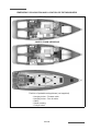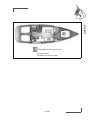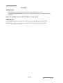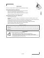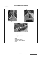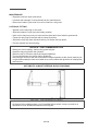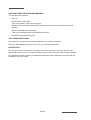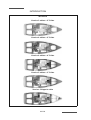
1
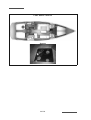
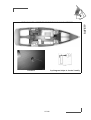
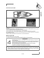
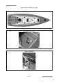
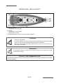
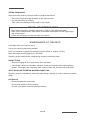
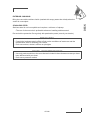
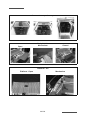
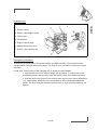
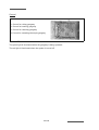
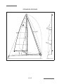
SUN ODYSSEY 509
CROISIERE
OWNER'S MANUAL
134614
Index F
WELCOME ABOARD
Madam, Sir,
You have just taken delivery of your new JEANNEAU boat and we thank you for the
confidence you have shown us in ordering a vessel of our brand. The whole JEANNEAU team
welcomes you aboard.
A JEANNEAU is made to last, in order to bring you all the pleasure you expect from a vessel
over a period of many years. Each boat is subject to the utmost attention to detail from the
design stage right through to launching.
This manual is meant to help you to enjoy your boat comfortably and safely. It includes the boat
specifications, the equipment provided or installed, the systems and tips on her operation and
maintenance. Some of the equipment described in this manual may be optional.
Your JEANNEAU dealer will be able to help and advise you in the use and maintenance of
your boat.
Read this user's guide/owner's manual carefully and get to know your boat before using it.
The better you know your vessel the more pleasure you will get from being at the helm.
The sea is a source for learning. Caution based on a knowledge of one's own limits and those
of the boat is the pre-requisite for an accomplished sailor.
Even when your boat has been adapted for them, the sea and wind conditions corresponding
to the design categories A, B, C and D may vary, ranging from severe conditions to strong
storms subject to the risks of exceptional waves and gusts of wind, this meaning they are
dangerous conditions in which only an experienced, fit and well trained crew manoeuvring a
well maintained boat can sail in a satisfactory manner.
This user's guide/owner's manual is not a course in safety at sea or about sailing sense. If this
is your first boat or if you change to a new type of boat which you are not used to, get some
training in boat control and sailing to ensure your safety and comfort. Your dealer, your
international sailing association or your yacht club will be very happy to recommend local
sailing schools or professional instructors.
Make sure the sea and wind conditions will correspond to the category of your boat and you
and your crew are able to handle the boat in these conditions.
Always listen to the weather forecast before you put out to sea.
Keep this user's guide/owner's manual in a safe place and hand it over to the new owner if
you sell your boat.
You are advised to keep all the instructions and manuals provided by the boat equipment
manufacturers (accessories...) in the same place as this manual
-1/192
INTRODUCTION
THE USERS OF THE BOAT ARE INFORMED OF THE FOLLOWING:
This user guide/owner's manual is not a maintenance or repair guide. In case of difficulty
do not hesitate to call on the services of your concessionaire JEANNEAU.
Any alterations which may affect the safety specifications of the boat must be assessed,
carried out and recorded by persons qualified to do so. Any change in the distribution of the
vessel's mass (adding a radar, altering the mast, changing an engine, etc) may affect the
stability, trim and performance of your boat.
The SPBI shipyards may not be held responsible for any alterations which they have not
approved.
The complete crew must be equipped appropriately.
In numerous countries, a licence, an authorization or a training course is requested. Make
sure you have this legal authorization before you use your boat.
Adapt the use of your boat to her condition that wears out with time and use.
Any boat, however solid she may be, may be severely damaged if badly used. This is not
compatible with safe navigation. Always adapt the speed and direction of your boat to the
conditions of the sea.
The boat shall not be loaded more with than the maximum load recommended by the
builder, in particular the total weight of the food supplies, of the different equipment that are not
supplied by the builder and of the persons on board.
The weight of the boat shall be properly distributed.
The stability is reduced when you add weight in the upper parts.
In case of heavy weather, the hatches, lockers and doors shall be closed in order to
minimize the risk of water coming in.
Breaking waves are a serious threat to stability.
The water in the bilge shall be kept at its minimum.
The stability may be reduced when you tow a boat or when you lift heavy weights with the
davits or the boom.
If your boat is equipped with a liferaft, carefully read the instructions. The boat must have
on board all the proper safety equipment (lifejackets, buoys, harness, flares, liferafts, etc.)
depending on the type of vessel, its certification, the country, the weather conditions
encountered, etc.
The crew must be familiar with the use of all the safety equipment and the emergency
safety procedures (MOB, towing etc.). Sailing schools organise regular training sessions.
1/192
Anyone on the deck shall wear a life jacket or a buoyancy aid.
The safety regulations as defined by the sailing code and enforced by the ’’COLREG’’ should
be observed.
NAME PLATE:
Some of the data is shown on the manufacturer's plate fixed to the boat. The explanation of the
data is given in the appropriate chapters of this manual.
IDENTIFICATION OF VESSEL:
The vessel's identification is found on the builder's certificate delivered with the boat and is
engraved on the starboard aft side.
So as to be able to continuously improve their product the SPBI shipyards reserve the right to
make any alterations in design, layout or equipment which they judge necessary.
That is the reason why the specifications and information given are not contractual, they may
be modified without prior notice or up dates.
This owner's manual is designed in accordance with the ISO 10240 standard requirements, it
has a general purpose and it may sometimes list some equipment or accessories or deal with
some points or questions that are not relevant to your own boat.
The different warnings used throughout this guide are broken down as follows.
DANGER
Indicates the existence of a serious inherent danger with a high risk of death
or serious injury if the appropriate precautions are not taken.
WARNING
Indicates the existence of a danger which could lead to injury or death if the
appropriate precautions are not taken.
PRECAUTION
Indicates a reminder of safety practice or draws attention to dangerous practices which
could cause injury to persons or damage to the vessel or to its components.
ADVICE - RECOMMENDATION
Indicates a recommendation or advice for carrying out manoeuvres appropriate for the
planned manoeuvres.
2/192
HISTORY OF UPDATES
• Index A ........................................................................................................................ 11/2011
• Index B ........................................................................................................................06/2012
• Index C ........................................................................................................................08/2012
• Index D ........................................................................................................................09/2013
• Index E ........................................................................................................................01/2014
• Index F.........................................................................................................................06/2014
3/192
CONTENTS
SUN ODYSSEY 509 Anglais
Update 06/2014
Index F
Code: 134614
Total number of pages: 192
INTRODUCTION
Chapter 1 ...... SPECIFICATIONS AND WARRANTY............................................Page 7
Chapter 2 ...... SAFETY ........................................................................................Page 13
Chapter 3 ...... HULL .............................................................................................Page 35
Chapter 4 ...... DECK ............................................................................................Page 39
Chapter 5 ...... STEERING SYSTEM ....................................................................Page 55
Chapter 6 ...... RIGGING AND SAILS...................................................................Page 63
Chapter 7 ...... INTERIOR .....................................................................................Page 83
Chapter 8 ...... WATER AND SEWAGE WATER .................................................Page 89
Chapter 9 ....... ELECTRICAL EQUIPMENT .......................................................Page 115
Chapter 10 .... ENGINE.......................................................................................Page 149
Chapter 11 .... LAUNCHING ...............................................................................Page 183
Chapter 12 .... WINTER STORAGE....................................................................Page 187
PERSONAL NOTES
5/192
1
SPECIFICATIONS AND WARRANTY
TECHNICAL SPECIFICATIONS
CERTIFICATION
DESIGN CATEGORY
YOUR BOAT
7/192
TECHNICAL SPECIFICATIONS
L.O.A....................................................................................................................... 15,38 m
L.O.A - with Optional equipment (Rear skirt) .......................................................... 15,63 m
Hull length............................................................................................................... 14,98 m
L.W.L. ..................................................................................................................... 14,15 m
Overall width ............................................................................................................. 4,69 m
Beam ........................................................................................................................ 4,69 m
Waterline beam......................................................................................................... 4,02 m
Air draught - Maximum ........................................................................................... 21,70 m
Keeled version - Shallow draught keel
Draught ................................................................................................................. 1,83 m
Ballast weight ..................................................................................................... 4 750 kg
Keeled version - Deep draught keel
Draught ................................................................................................................. 2,36 m
Ballast weight ..................................................................................................... 4 300 kg
Light displacement............................................................................................... 14 527 kg
CERTIFICATION
CE Category
A
B
C
D
13
14
16
16
Displacement with maximum load
19 467 kg
19 467 kg
19 467 kg
19 467 kg
Maximum load recommended by
the builder
4 940 kg
4 940 kg
4 940 kg
4 940 kg
Persons maximum
Including the mass of the persons who are authorized on board (75 kg/165 lbs per adult),
the supplies, the liquids that can be used (fresh water and fuel) in fixed completely full
tanks, the additional loads, the optional equipments, the liferaft and the scope for load.
Total mass of liquids (all tanks full)........................................................................ 1 156 kg
Freshwater capacity........................................................................................... 400 + 235 l
Fuel capacity................................................................................................................ 237 l
Refrigeration unit capacity ........................................................................................... 255 l
Sewage water capacity.............................................................................................4 x 80 l
Recommended maximum power ............................................................................... 55 Kw
Maximum motorisation mass .................................................................................... 207 kg
Battery capacity - Engine.............................................................................................110A
Battery capacity - Service ...................................................................................... 3 x 110A
Battery capacity - Spare battery ............................................................................ 2 x 110A
Battery capacity - Bow thruster................................................................................ 4 x 50A
Cabins.......................................................................................................................... 3/4/5
Architect....................................................................................................Philippe BRIAND
Note: The capacities indicated are maximum (including options).
8/192
Mainsail (classic) - Classic................................................... 60,90 m²
Genoa - Classic ................................................................... 52,70 m²
Furling mainsail.................................................................... 49,20 m²
Mainsail (classic) - Performance.......................................... 60,90 m²
Genoa - Performance .......................................................... 72,20 m²
Tacking jib................................................................................. 44 m²
Asymmetric spinnaker ............................................................ 190 m²
Symmetrical spinnaker ........................................................... 190 m²
I ..............................................................................................19,06 m
J ............ 5,49 m / 5,93 m (Classical mast / Mast with in-mast furling)
P ...........................................................................................17,50 m
E ..............................................................................................6,00 m
The sails are the main propulsion means of the SUN ODYSSEY 509.
DESIGN CATEGORY
Design category
Vessel designed for navigation:
A - "At high sea"
B - "In open sea"
C - "Near to the coast"
D - "In sheltered waters"
Wind force
(Beaufort scale)
Significant height of
waves to be considered
(in metres H 1/3)
Over 8
Up to and
including 8
Up to and
including 6
Up to and
including 4
Over 4 m
Up to and including 4 m
Up to and including 2 m
Up to and including 0,5 m
.
9/192
SPECIFICATIONS AND WARRANTY
1
SAILS
Category A: At high sea
This craft is designed to operate in winds that may exceed wind force 8 (Beaufort scale) and in
significant wave heights of 4 m and above.
This craft is largely self-sufficient. Abnormal conditions such as hurricanes are excluded.
Such conditions may be encountered on extended voyages, for example across oceans, or
inshore when unsheltered from the wind and waves for several hundred nautical miles.
Category B: In open sea
This craft is designed to operate in winds up to Beaufort force 8 and the associated wave
heights (significant wave height up to 4 m, see Note 1 below).
Such conditions may be encountered on offshore voyages of sufficient length, or on coastal
waters when unsheltered from the wind and waves for several dozens of nautical miles.
These conditions may also be experienced on inland seas of sufficient size for the wave height
to be generated.
Category C: Near to the coast
This craft is designed to operate in winds up to Beaufort force 6 and the associated wave
heights (significant wave height up to 2 m, see Note 1 below). You may meet with such
conditions in exposed inland waters, in estuaries and in coastal waters with moderate weather
conditions.
Category D: In sheltered waters
This craft is designed to operate in winds up to Beaufort force 4 and the associated wave
heights (occasional maximum waves of 0,5 m height).
Such conditions may be encountered in sheltered inland waters, and in coastal waters in fine
weather.
NOTE:
- The significant wave height is the mean height of the highest one-third of the waves, which
approximately corresponds to the wave height estimated by an experienced observer. Some
waves will be double this height.
- The creation of different design categories results from the need to distinguish between
different levels of risk according to the construction of the boats.
The parameters for the characteristics are established to define the conditions of navigation
which each category may encounter; they serve purely to evaluate the boat designs and are
not to be used to limit the geographical areas in which these boats may operate.
- One boat may be classed in several design categories at the same time, each with their
different maximum capabilities.
10/192
YOUR BOAT
NAME OF THE BOAT
.............................................................
NAME OF THE OWNER
.............................................................
ADDRESS
.............................................................
.............................................................
.............................................................
HULL NUMBER
.............................................................
SERIAL NUMBER
.............................................................
REGISTRATION NUMBER
.............................................................
DELIVERY DATE
.............................................................
DOOR KEY NUMBER
.............................................................
MAKE OF ENGINE
.............................................................
ENGINE SERIAL NUMBER
.............................................................
ENGINE KEY NUMBER
.............................................................
Your agent
JEANNEAU (Establishment of the company SPBI)
BP 529 - 85505 LES HERBIERS cedex - FRANCE
Tel. (33) 02 51 64 20 20 - Fax (33) 02 51 67 37 65
Internet : http://www.jeanneau.com(fr).
11/192
SPECIFICATIONS AND WARRANTY
1
Version
2
SAFETY
SAFETY EQUIPMENT
GENERAL INFORMATION
GAS SYSTEM
RECOMMENDATIONS FOR GAS
FIGHT AGAINST FIRE
BILGE PUMP SYSTEM
EMERGENCY TILLER
13/192
SAFETY EQUIPMENT
Swimming ladder (means of coming back onboard)
(Reference 1)
14/192
folding bathing ladder
(Reference 2)
GENERAL INFORMATION
2
DANGERS
The major hazards concern:
SAFETY
- The gas system.
- The electrical system.
- Manoeuvring the vessel and the sails.
- The motorisation.
Please refer to the relevant paragraphs.
DANGER
- Fuel leaks or vapour represent a danger of fire and explosion.
- Leave the engine compartment ventilated for a long time before starting the
engine.
- There may be danger of fire or explosion if direct or alternating current
systems are incorrectly used. Refer to chapter Electricity.
- Certain vessels are equipped with a retractable swimming ladder. The
swimming ladder must be in position as soon as you are onboard.
- Reduce speed in waves.
WARNING
- Before you sail, list the compulsory safety equipment.
- Don't exceed the number of persons indicated in the chapter
'Specifications'.
- The total weight of the persons and equipment must never exceed the
maximum load recommended by the manufacturer.
- Use the seats provided.
ADVICE - RECOMMENDATION
- When sailing, never padlock or lock the liferaft locker.
- Before putting to sea, carefully read the launching instructions shown on the liferaft.
- Close the deck hatches and portholes before each trip (including the companionway
hatch in heavy weather).
- Don't store anything below the floorboards.
- Ensure that movable items are firmly secured when the boat is under way.
15/192
GAS SYSTEM
LOCATION
REF
1
2
3
4
5
Designation
Gas cylinder locker
Kitchen sink evacuation through-hull
Drain - Gas cylinder locker
Gas system
Supply valve - Gas
16/192
2
SAFETY
SCHEMATIC DIAGRAM FOR GAS SYSTEM - EUROPE
1
5
GAZ
4
gaz
6
7
2
REF
1
2
3
4
5
6
7
3
Designation
Connection kit gas bottle
Drain
Gas cylinder
Connection kit gas copper
PVC girdled sleeve
Gas appliance connection kit
Wire passage
17/192
GAS CYLINDER LOCKER - LOCATION
Gas cylinder locker
Note: Same position for the other layouts.
Opening valve / Reheating gas closing
REF
6
7
Valve
Designation
Open valve
Closed valve
18/192
2
SCHEMA GAS - US
SAFETY
1
4
5
2
6
3
REF
1
2
3
4
5
6
7
Designation
Regulator valve 12V
Gas cylinder
Drain
Stuffing box
PVC girdled sleeve
Electromagnetic valve for gas 12V
Pipe Propane Plastic
19/192
7
RECOMMENDATIONS FOR GAS
Type of cylinder: butane, service pressure 10 kg/cm2 or according to current standards of your
country).
Close the valves on the system and on the cylinder when the appliances are not used. Close
the valves before you change cylinders and immediately in case of emergency.
Never leave unattended an appliance that is working. Don't install or store flammable materials
above or over the stove (curtains, papers, napkins etc.).
Make sure that the valves of the appliances are closed before you open the cylinder or hose
valve.
In case you smell gas or find that the burners have gone out (although appliance models cut
off automatically if the flames go out), turn off the valves of the appliances. Do ventilate the boat
in order to get rid of any residual gas. Find the cause of the problem.
Regularly test the gas system in order to detect any gas leak.
Check all the connections using water and soap or detergent, closing the valves of the
appliances and opening the valve on the cylinder.
If you detect a leak, close the valve of the cylinder and repair before you use it again.
The appliances use the oxygen of the cabin and release combustible gases. Ventilate your boat
when using appliances.
Don't obstruct the air vents and at least leave the door open. Don't use the oven or stove as
back up heaters.
Lock the stove oven when being not used in order to avoid damaging the tubes when sailing.
WARNING
-
For all recommendations concerning gas: Refer to chapter 2, «Safety».
Don't use a solution containing ammonia.
Don't use a flame to detect leaks.
Don't smoke, don't use a naked flame when you change the gas cylinder.
ADVICE - RECOMMENDATION
- Shut off the gas supply at the bottle as well as the cooker tap.
- When changing the cylinder, refit the cap in place on the regulator threaded section (to
avoid corrosion).
- For winter storage instructions and precautions, refer to Chapter 12.
Never obstruct the fast access to the components of the gas system. Keep the taps of the
empty cylinders turned off and the cylinders disconnected.
Keep the protection, lids, covers and taps in their places.
Don't use the gas cylinder storage place to store other equipment. Only use the proper locker
to store the gas cylinders.
20/192
2
Pay particular attention to keep in good condition the screw thread of the cylinder on which the
regulator is. Check the condition of the regulator every year and change it if necessary. Use
regulators identical to the ones that are fitted.
Have the repairs carried out by someone skilled.
POSITION OF GAS BOTTLE
The locker for storing gas bottles can be reached through the cockpit under the foldaway seat.
The locker can accommodate 2 gas bottles. The locker is equipped with bottle fastening straps.
FIGHT AGAINST FIRE
It is the owner's or the skipper's responsibility:
- To have the extinguishers checked in pursuance of the instructions given.
- Use extinguisher replacements with equivalent features (same capacity and fire
resistance) if the ones in place are out of date or have been used.
- To tell the crew:
- where the extinguishers are and how they work,
- where the release aperture is situated in the engine compartment,
- where the emergency exits are.
- Make sure the extinguishers can be reached easily when people are on board.
- Make sure that the ventilation openings in the engine (and generator, if installed)
compartment are well cleared.
Keep the bilge clean. Regularly check that there is no fuel or gas vapour.
Do not store combustible materials in the engine compartment.
If non-combustible materials are stored in the engine compartment they must be secured so
there is no danger of them falling on machinery and they do not obstruct access to and from
the compartment.
Always fasten the curtains open when the gas cooker is working.
Exits other than the doors and hatches of the main companionway, equipped with permanently
fitted ladders, are identified with a symbol.
WARNING
- Keep an extinguisher handy in case the fire should start again.
- Fire fighting equipment (portable extinguishers, fire blankets and buckets)
must be permanently and immediately accessible.
21/192
SAFETY
Regularly check and replace the rubber tubings that link the cylinder to one end of
the circuit and the stove to the other one, depending on the norms and regulations in
force in your country.
EMERGENCY EVACUATION AND LOCATION OF EXTINGUISHERS
VERSION 3 CABINS
4 AND 5-CABIN VERSIONS
Position of portable extinguishers (not supplied)
- Hanging locker - Forward cabin
- Hanging locker - Port aft cabin
- Galley
- Saloon seating
- Cockpit locker
22/192
SAFETY
2
Emergency exits in case of fire
-Companionway
-Deck hatch of the fore cabin
23/192
EXTINGUISHERS
The extinguishers are part of the compulsory equipment.
2
An extinguisher or a fire blanket shall be set less than 2 m from any flame appliance.
It is compulsory for an extinguisher to be placed less than 2 m away from the extinguisher
aperture of the engine compartment.
An extinguisher shall be less than 1 m from the steering station.
The extinguishers must be in position (see "Extinguisher positions" diagram).
Extinguisher, per unit, minimum capacity 5 A/34 B.
For the Sun Odyssey 439: 20A/136B (4 extinguishers of this minimum capacity).
DANGER
- There may be danger of fire or explosion if direct or alternating current
systems are incorrectly used (Refer to chapter Electricity).
WARNING
- Do not obstruct the ways to the emergency exits.
- Do not obstruct the safety controls (fuel oil valves, gas valves, power
switches).
- Do not block the extinguishers placed on shelves.
- Do not leave the vessel unattended when a cooker or heater is in use.
- Do not use gas lamps in the vessel.
- Do not alter the vessel systems (electrical, gas or fuel).
- Do not fill up a tank or change a gas cylinder when an engine is running or
a cooker or heater is on.
- Do not smoke while handling fuels or gas.
WARNING
- The CO² extinguishers shall be used only to fight electrical fires.
- Clear the area immediately after use in order to avoid suffocation.
- Air before entering.
25/192
SAFETY
Extinguishers must be placed less than 5 m from any berth.
FUEL SUPPLY VALVE
Access
26/192
2
SAFETY
EXTINGUISHER APERTURE OF THE ENGINE COMPARTMENT
Location
A pictogram helps to locate it easily
27/192
The engine compartment has a port that makes it possible to inject the extinguishing product
inside without opening the usual access hatches.
INSTRUCTIONS TO FOLLOW IN CASE OF A FIRE IN THE ENGINE COMPARTMENT
BILGE:
- Stop the engine.
- Switch off power and stop fuel supply.
- Block off the air supply from the air inlets and outlets of the engine.
- Inject the extinguishing product through the aperture.
- Wait.
- Open the access hatches and repair.
28/192
2
SAFETY
MANUAL BILGE PUMP
Arm - Pump
Location
Cockpit locker Port aft
Operation
Manual pump
Capacity:
0,7l / blow
BILGE PUMP SYSTEM
PROCEDURE TO BE FOLLOWED
- Switch on the electric bilge pump.
- If necessary activate the manual pump.
- Identify the source of the leak by tasting the water and decide on the relevant action to be
taken:
• freshwater = watertank leak.
• seawater = breach of hull.
WARNING
- Let open the floodgates navigation.
29/192
DIAGRAM OF THE LAYOUT - SYSTEM - BILGE DRAINING
Pipe - Bilge pump system (25 mm diameter)
Pipe - Bilge pump system (20 mm diameter)
REF
Designation
13
Electric bilge pump
14
Stuffing box - Manual bilge pump
15
Thru-hull fitting - Draining of manual bilge pump
16
Electric bilge pump
17
Non-return valve
18
Thru-hull fitting - Electric bilge pump draining
32
Electric bilge pump
30/192
2
ELECTRIC BILGE PUMP
SAFETY
LOCATION
In the sump well
Sail locker
Operation:
The electric bilge pumps are connected to the 12V service circuit. To enable operation the 12V circuit
must be activated by turning on the battery switches.
You can energize the electric bilge pump from the electrical panel.
On the electrical panel - three possible positions : OFF / Automatic / Mechanically operated.
In the automatic position each pump is set off automatically by a trip switch located in the sump area or
in the bottom of the hull.
Capacity: Refer to manufacturer's instructions for use and maintenance.
MANUAL BILGE PUMP
The manual bilge pump is in the cockpit
The control arm of the pump shall be kept accessible whatever the circumstances.
WARNING
- The bilge pump system is not designed to provide buoyancy to the boat in
case of damage.
- The bilge pump system is designed to drive out the water being either sea
spray or leaks but absolutely not the water coming through a hole in the hull,
this hole being the result of a damage.
- Do not let the pumps run while dry, this may cause them damage.
- The water in the bilge shall be kept at its minimum.
- Check the functioning of each bilge pump regularly.
SAFETY PRECAUTIONS
- Clean off debris which could block the pump intake points or strainers. If the watertight
partitions which seal off the fore and aft points are fitted with valves they must be closed
at all times and only opened to drain water into the main bilge.
31/192
USE STEERS FRANK OF HELP
Sector access port
Opening access hole
Tiller in position
32/192
EMERGENCY TILLER
2
To operate the tiller:
- Use a winch handle and unscrew the tiller cover situated at the back of the cockpit.
- Insert the tiller into the rudder stock and make sure it is fully secure in the square.
- If the automatic pilot is connected and is working after the tiller damage, use it.
- Disconnect all apparatus linked to the rudder stock to use the emergency tiller.
ADVICE - RECOMMENDATION
The emergency tiller is designed only to be able to continue underway at a reduced
speed in case of steering gear failure.
33/192
SAFETY
The emergency tiller is in an aft locker and shall be easy to get to.
3
HULL
MAINTENANCE OF THE HULL
LIFTING
35/192
LIFTING
Wetted area: approx.50 m²
Note: Measurements are expressed in mm.
PRECAUTION
- Consult the harbourmaster's office to find out the conditions of water use and the
maintenance area for cleaning your vessel.
- It is necessary to seek the advice of your concessionnaire with regard to gel-coat repairs.
PRECAUTION
- When applying the anti-fouling paint do not paint over the electronic instrument sensors
nor the anodes.
ADVICE - RECOMMENDATION
- During the refit, check the anodes (See "Motorisation" chapter).
- When the boat is stored at a dry dock, the corrosion protection is not as effective due to
oxidation of the anodes: even the new anodes oxidize the surface. Before returning the
boat into the water, clean the anodes.
- Cleaning anodes: Use sandpaper.
Do not use metal brushes or steel tools to clean the boat, it may damage the galvanic
protection.
- Replacing the anodes: The anodes are fastened with screws and nuts. First, remove the
screws and nuts that hold the anode, then clean the contact surface. Press the new anode
to obtain a good electrical contact.
36/192
MAINTENANCE OF THE HULL
3
Preferably wash your boat on shore.
Use as few cleaning agents as possible.
Don't use solvents or aggressive detergent agents. Don't discharge cleaning agents into the
water.
LIFTING
The lower hull of your boat should be covered with an anti-fouling paint which will prevent the
adhesion of marine growth.
The nature of the water in which the boat sails will determine the choice of the anti-fouling paint
as well as the frequency of hull stripping and painting. Do not hesitate to take advice from your
specialists.
Refer to chapter 11 for launching instructions.
Before applying anti-fouling paint never:
- Do any sandblasting.
- Use any other solvents than ethylic alcohol.
- Use detergents under pressure.
- Use scrapers.
- Do any sanding other than a light rubbing down by hand with a grade 400 wet abrasive
paper (for the first application).
If cleaning of the anti-fouling paint has to be done with a high pressure hose:
- The water temperature must not exceed 15 °C.
- The water pressure must not exceed 150 bars.
- The distance between the hose nozzle and the hull must not be less than 10 centimetres.
Follow the supplier's instructions very closely when applying the anti-fouling paint.
All these hull maintenance operations can be carried out by your dealer.
37/192
HULL
The materials and equipments of your boat have been selected because of their high
quality and performance and ease of maintenance. However you shall carry out a
minimum maintenance in order to protect your boat from outside attacks (salt, sun, electrolysis
...).
4
DECK
NAVIGATION- DECK LAYOUT
STABILITY
PREVENTION OF MAN OVERBOARD
MOORING LINES
TOWING
MOORING
MAINTENANCE OF THE DECK
39/192
NAVIGATION - DECK LAYOUT
- A. Mooring cleats
• Jacklines - not supplied
- B. Towing:
• at the bow, to be towed
• at the stern, to tow
- C. Swimming ladder (means of coming back onboard)
DANGER
-
Wear your life jacket.
In heavy weather, wear your safety harness and fasten yourself to the boat.
When at sea close the guardrail side-opening or openings.
Do not try to stop the boat using a boat hook or your foot, your hand or any
other part of the body.
WARNING
The sudden closing of a locker due to a gust of wind or movement of the boat
could result in injury.
ADVICE - RECOMMENDATION
Close the deck hatches and portholes before each trip (including the companionway hatch
in heavy weather).
40/192
STABILITY
Breaking waves represent a serious danger for stability and for taking in water. Close
the companionway doors and hatches in heavy seas.
4
- The stability is reduced when you add weight in the upper parts.
- Stability may be reduced when towing a boat or when heavy weights are lifted with the
davits.
PREVENTION OF MAN OVERBOARD
Regularly check the guard-rails:
- With metal guard-rails, watch for corrosion particularly at connecting points.
- With synthetic guard-rails, change them as soon as they show signs of wear due to chafing
or UV.
Areas forbidden when sailing.
- Aft quarterdeck
- Roof
MOORING LINES
A sufficient number of mooring lines suitably sized and suitable for the environment shall be on
board for mooring your boat.
- Always manoeuvre your boat using the engine.
- Make allowance for the current and wind when you handle your boat.
- Protect your boat to the highest degree with suitably sized fenders.
- Always keep the mooring ropes unfouled and stored away.
- Handle your boat at a reduced speed.
AFTER MOORING
- Protect the mooring lines against chafing with plastic sleeves.
- Make allowance for the variations in tides if need be.
41/192
DECK
During sailing keep all the portholes, windows and doors closed.
TOWING
TOWING BOAT
- Tow another boat at a reduced speed and as smoothly as you can.
- Pay particular attention when you throw or catch the towing rope (it may foul on the
propeller).
Note: The stability may be reduced when you tow a boat.
TOWED BOAT
Keep steering your boat and see to it that you stay in the wake of the towing boat.
Inappropriate towing can damage your vessel, do not tow at more than 6 knots.
42/192
MOORING
As a rule, set the anchor in at least 3 times the depth of water.
4
-
Have your boat pointed into the wind and without speed.
Pay out the chain while moving back slowly.
Once the anchor snags, make it fast by reversing slightly.
Secure the hawser or the chain to the cleat.
ANCHORING WITH ELECTRIC WINDLASS
- Turn on the boat engine.
- Check that the electrical supply of the windlass is switched on (battery switch, circuit
breaker).
- Use the remote control to activate the windlass in lowering mode. Let the chain feed out
by keeping the lowering button on the remote control pressed down.
- Let the chain out while moving backwards slowly and as straight as possible.
- Once the anchor snags, make it fast by reversing slightly.
- Secure the hawser or the chain to the cleat.
PRECAUTION
- Before anchoring check the depth of water, the power of the current and the nature of the
sea bed.
- Anchoring manoeuvres with the electric windlass can only be carried out with the engine
running.
WARNING
Windlass operations are dangerous:
- Always keep the anchor chain or rode free and unfouled.
- Always proceed with care, using gloves and always wearing shoes.
- If your boat is equipped with the twin control optional extra, make sure you
use only onecontrol at the same time.
43/192
DECK
ANCHORING WITHOUT WINDLASS
ELECTRIC WINDLASS - BREAKER
LOCATION
1.
2.
3.
4.
5.
6.
7.
8.
Stem roller
Mooring locker
Opening - Mooring locker
Remote control
Handle
Windlass 12V 1000W
Chain rim - 10 mm diameter
Clinch
44/192
4
The winch is powered by battery park easements.
Turn on the boat engine.
Relay box
Location: Sail locker
100A breaker
ANCHORING BY HAND WITH USE OF A MANUAL WINDLASS
- Release the windlass brake using the handle located in the chain locker so as to allow the
chain lifter to turn freely and to release the anchor from the stem fitting
- Re-engage the brake and let the anchor hang until the mooring position is reached.
- Have the boat pointed into the wind and without speed.
- Release the brake and pay out the chain slowly.
- Control the speed of anchor lowering using the brake.
- Once the anchor has taken hold re-engage the brake and secure the hawser to the cleat.
HEAVING UP THE ANCHOR
- Lock the cable lifter snubber.
- Ensure the chain is properly set on the cable lifter.
- Slowly go near the anchor, using your engine (Don't use your windlass to winch the boat).
- Heave the anchor completely.
- Visually check the last meters till the anchor gets into contact with the davit.
- If you just change berth, check the position of the anchor on the stem fitting.
- For sailing, store the anchor in the chain locker or fasten the anchor to its roller.
- For electrical windlasses cut off the power supply as soon as the anchor has been lifted.
45/192
DECK
OPERATION
STERN ANCHORING
Stern anchoring shall be performed with the engine declutched.
- Secure the required length of cablet on the mooring cleat.
- Pay out the anchor line slowly.
- Take care not to damage the propeller or the rudder.
ADVICE - RECOMMENDATION
- After each trip rinse the windlass and anchor chain or rode with fresh water.
- Refer to the manufacturer's instructions for windlass maintenance at the beginning or
end of the season.
- Check the swinging area once the boat is at anchor.
MAINTENANCE OF THE DECK
Preferably wash your boat on shore.
Use as few cleaning agents as possible.
Don't use solvents or aggressive detergent agents (Refer to chapter 3 "Hull").
Don't discharge cleaning agents into the water.
Regularly brush the deck with a degreasing shampoo and fresh water.
DECK FITTING
- Rinse thoroughly all your equipments with fresh water.
- Periodically lubricate turnbuckles, winches, tracks and travellers with water-repellent
grease. Thoroughly and frequently wash off the pulleys and sheaves with clear water.
SOLID WOOD ON EXTERIOR WOODEN PANELLING
Regularly clean the woodworks with fresh water using a sponge (if need be add some gentle
soap).
PLEXIGLAS
- Rinse plexiglas with fresh water.
- Use a polish paste for thin scratches.
- Consult your dealer concerning deep scratches.
46/192
4
EXTERIOR CUSHIONS
STAINLESS STEEL
Stainless steel is not incorruptible and requires a minimum of upkeep:
- The use of chrome tools is preferable whenever handling stainless steel.
Re-nourish the protective film regularly with passivation paste (consult your dealer).
PRECAUTION
- Consult the harbourmaster's office to find out the conditions of water use and the
maintenance area for cleaning your vessel.
- Don't use solvent, alcohol, acetone on plexiglas.
ADVICE - RECOMMENDATION
- Use only products similar to the ones that are included in the maintenance case you have
been delivered with your boat.
- Don't use a pressure washer.
47/192
DECK
Bring the removable cushions inside (washed with soapy water then dried) when the
vessel is unoccupied.
.
Access to companionway
Open
Cockpit table
Mechanism
Closed
Platform - aft
Platform - Open
Mechanism
48/192
Gangway
4
Description
- The gangway is hydraulic and telescopic (adjustable length); fixed.
- The gangway control is situated in the cockpit.
- The gangway is comprised of the external part and a hydraulic unit situated in the engine
compartment.
- A control box situated on the hydraulic unit prevents accidental operation of the control
panel. As a precaution it is advised to leave it on the 'AUTO' setting.
- The hydraulic pump controlled by the electric motor is situated under the hydraulic unit
reservoir. The motor has a speed regulator: it controls the speed at which the gangway moves.
- The gangway can also serve as a davit for lifting out the tender.
Operation
- The gangway runs on DC power.
- A breaker protects the electrical circuit.
- The gangway motor is designed to run continuously for a maximum of 4 minutes. After this
the motor will cut out automatically (risk of overheating).
49/192
DECK
- The gangway allows you to embark/disembark easily when the boat is moored stern on
to the pontoon.
Maintenance
- Wash the gangway off regularly with clean water.
- Its location at the stern of the boat makes the gangway particularly prone to fouling due to
the exhaust gases: clean the fouled areas regularly with a non-abrasive detergent.
- Change the oil in the hydraulic unit at least once a year.
- Regualrly check the connections which could loosen with vibration.
DANGER
- Do not use the gangway when at sea.
- Never manoeuvre the gangway with anyone on it, below it or within its arc
of movement.
- Do not use the gangway as a diving board.
ADVICE - RECOMMENDATION
- Refer to manufacturer's instructions for use and maintenance.
- Maximum load permitted on gangway: 110 kg.
- Telescopic gangway: Ensure that the stanchions are correctly seated in their sockets
before recovering the gangway.
- Manual operation prevents the position sensors from working: the electronics are no
longer able to correct the alignment of the gangway if it is not retracting correctly into its
housing. Use this procedure with caution.
50/192
4
DECK
Hydraulic unit
1. Electric valves
2. Electric valve support block
3. Oil filler cap
4. Oil reservoir
5. Engine support block
6. Manual emergency lever
7. Electric valve opening cap
Emergency procedure
In the event of power failure the system can be operated manually. The hydraulic unit is
equipped with a manual emergency pump. The electric valve can also be opened or closed
manually.
In this case, manoeuvring of the gangway will be slower but still possible:
1. Activate the lever of the manual pump with one hand. To control one of the
available hydraulic manoeuvres, open the electric valve of the desired function.
2. With the other hand, press on the electric valve opening cap using a pointed tool
(e.g. screwdriver). When the lever is operated, oil will be directed towards the
piston. The lever must be activated several times to expel air and pressurise the
system.
51/192
Control
1. Control for raising gangway
2. Control for lowering gangway
3. Control for retracting gangway
4. Control for extending telescopic gangway
The ON/OFF button turns the control on and off.
The green light is illuminated when the gangway is being operated.
The red light is illuminated when the system is turned off.
52/192
4
DECK
General view
Hydraulic unit
Access: Cockpit locker - aft
Control
53/192
5
STEERING SYSTEM
STEERING GEAR
LOCATION - SCHEMATIC DIAGRAM
55/192
STEERING GEAR
Access: Aft cabins
Sheaves - Ropes
Steering sector
56/192
STEERING GEAR
- Regularly check:
• The tension in the steering cables.
• The tightness of the steering system components.
- Don't tighten the steering cables excessively.
- Lubricate all the elements.
Maintain the nylon, ertalon or teflon bushes with only a suitable lubricant.
Note: Do not hesitate to consult your dealer about system maintenance.
WARNING
- Refer to chapter 2 "Safety"for use of the emergency tiller.
ADVICE - RECOMMENDATION
- The emergency tiller is designed only to be able to continue underway at a reduced
speed in case of steering gear failure.
CABLE ADJUSTMENT - STEERING SYSTEM
The steering gear is assembled and pre-adjusted at the factory, however, only actual use at
sea will enable the steering cable to find its definitive postion around the wheel drum.
For this reason, it is necessary to re-adjust the gear after the first few sea outings.
WARNING
- The steering system is a feature of sailing safety and for this reason must
be verified at least once a year.
- The steering cable must be changed every 10 years.
57/192
STEERING SYSTEM
5
MAINTENANCE
LOCATION - SCHEMATIC DIAGRAM
58/192
LOCATION
STEERING SYSTEM
5
59/192
LOCATION
60/192
5
Designation
Rudder
Rudder stock
Bronze bush
Flange
Balance bush
Rudder port tube
Flange
Bronze bush
Bearing rudder trunk
Flange
Pin - Sector
Steering sector
Autopilot ram
Axis cylinder
Emergency tiller
Emergency tiller hole
Steering wheel
Hub - Starboard
Hub - Port side
Sheave - lit
Movable Sheaves
Chain
Line
Mount - Sector stopper
Sector stopper
Mount - Hydraulic pump
Hydraulic pump
Mount - Indicator - Pilot
Indicator - Pilot
61/192
STEERING SYSTEM
REF
1
2
3
4
5
6
7
8
9
10
11
12
13
14
15
16
17
18
19
20
21
22
23
24
25
26
27
28
29
6
RIGGING AND SAILS
STANDING RIGGING
RUNNING RIGGING
WINCHES
SETTING THE SAILS
SAILS
RUNNING RIGGING SYSTEM
63/192
STANDING RIGGING
6
5
1
2
4
3
64/192
6
Designation
1
Forestay
2
Backstay
3
D1
4
V1
5
D2
6
V2D3
STANDING RIGGING
Your JEANNEAU dealer was responsible for stepping the mast of your boat.
After masting your vessel and after having sailed for the first time it is necessary to seek the
help of a qualified specialist in order to carry out a rigging check.
MAINTENANCE
Before each trip, carefully inspect the mast from top to bottom.
Periodically check the rigging tightening and the lock nut or pin locking (you should check it for
the first time after a few days sailing in all types of weather).
DANGER
- To hoist a crew member up to the top of the mast, make a bowline with the
halyard directly on the bosun's chair ring (never use the halyard snap
shackle or shackle).
- Do not hoist a crew member when sailing in heavy weather.
ADVICE - RECOMMENDATION
Your dealer JEANNEAU can carry out all maintenance operations or recommend a skilled
specialist to do so.
65/192
RIGGING AND SAILS
REF
RUNNING RIGGING
MAINTENANCE
Change any distorted or dented sheave. Inspect the pins of the sheaves at the top of the mast
once a year.
Lightly grease the sheave pins.
Regularly check the condition of the jam cleat jaws.
Inspect the halyards for wear and condition.
Regularly clean the pulleys off (old grease, traces of rust) with clear water.
Slightly lubricate the block pins.
Avoid aggressive gybing in order to reduce premature wear on the sheets, attachment points
and the gooseneck.
WINCHES
OPERATION
Avoid rope jamming during winch handling. Do not leave loose ropes on the winches but make
them fast on cleats (except on the ’’Self Tailing’’ winches).
SETTING THE SAILS
CLASSICAL MAINSAIL
With the mainsail being on the deck:
- Screw the pins of the mast sliders for battens into their boxes.
- Slide in the battens through the leech.
- Screw the box cap until you get the required tension (the tightening screw shall not project
beyond the sail).
- Do not forget the small locking screw.
- Put the mainsail into the lazy-bag.
- Set the boom ring in velcro about level with the clew.
- Fit the mainsail onto its slides, begin with the headboard and finish with the tack.
WARNING
-Refer to the manufacturer's instructions to remove the winches and put
them back.
Improper refitting may result in accidents (e.g. kick of the crank handle).
66/192
- Remove the hatch giving access to the furling mechanism.
- Spread out the sail on the deck.
- Fasten the head (strap) to the shackle of the upper swivel. Pay attention to the winding
direction.
- Insert the foot adjustment line into the clew block.
- Slowly hoist the sail. Guide the bolt rope (sometimes the groove leading edges may be
insufficiently smoothed off).
- When the sail is up, tack it to the lower shackle.
- Gently sweat up the halyard.
- Refit the hatch.
- Furl the sail facing the wind and keeping a very slight tension on the foot. The mainsail
downhaul and sheet shall be eased off.
ADVICE - RECOMMENDATION
- Carry out the complete maintenance of the winches regularly (before and during the
sailing season).
- Rinse the winches off regularly during the season.
67/192
RIGGING AND SAILS
6
FURLING MAINSAIL
RUNNING RIGGING SYSTEM
RIGGING DIAGRAM
22
1
23
2
3
3
4
19
20
21
16
17
18
10
11
12
13
14
15
9
4
5
5
6
6
7
2
4
2
4
3
3
7
8
8
68/192
6
15
16
17
18
19
20
21
22
23
Designation
Genoa furler
Mainsail sheet
Genoa sheet
Two-way switch - Genoa
Spinnaker guy
Genoa sheet - Performance
Cable adjustment - Genoa - Performance
Spinnaker sheet
Traveller adjustment - Mainsail (classic)
Genoa furler line
Genoa halyard
Main halyard
Reef 2 (Classical mast)
Reef 3 (Classical mast)
Kicking strap (Classical mast ) /
Mainsail safety block stopper (Mast with in-mast furling)
Mainsail foot
Reef 1 (Classical mast) / Kicking strap (Mast with in-mast furling)
Spinnaker halyard
Boom lift / Fore stay sail halyard
Spinnaker boom downhaul / Asymmetric spinnaker tack
Traveller adjustment - Mainsail (classic)
Kicker tackle - Symmetric spi / Asymmetric spinnaker tack
SHEET - Tacking jib
69/192
RIGGING AND SAILS
REF
1
2
3
4
5
6
7
8
9
10
11
12
13
14
RUNNING RIGGING SYSTEM
MAST FOOT - CLASSICAL MAST
Port side
1
2
4
3
5
REF
1
2
3
4
5
Designation
Genoa halyard
Main halyard
Reef 2
Kicking strap
Reef 3
Starboard
7
6
8
9
10
REF
6
7
8
9
10
Designation
Mainsail foot
Boom lift / Fore stay sail halyard
Spinnaker halyard
Reef 1
Spinnaker boom downhaul / Asymmetric spinnaker tack
70/192
6
MAST FOOT - MAST WITH IN-MAST FURLING
RIGGING AND SAILS
Port side
1
2
3
4
REF
1
2
3
4
Designation
Genoa halyard
Main halyard
Main furling line
Genoa furler
Starboard
6
5
7
8
9
REF
5
6
7
8
9
Designation
Mainsail foot
Boom lift / Fore stay sail halyard
Spinnaker halyard
Kicking strap
Spinnaker boom downhaul / Asymmetric spinnaker tack
71/192
RUNNING RIGGING SYSTEM
SYSTEM - MAINSAIL (CLASSIC)
A
7
1
5
2
6
8
3
4
A
Red
Green
REF
1
2
3
4
5
6
7
8
Reeving - Classical mainsail
Version: Mast with in-mast furling
Version: Classical mast
Designation
Kicking strap (Diameter = 12 mm / Length = 14 m)
Swivel single pulley (Diameter = 75 mm)
Mainsail sheet (Diameter = 12 mm / Length = 40 m)
Two-way switch - Mainsail sheet (Diameter = 8 mm /
Length = 8 m)
Single frame pulley (Diameter = 75 mm)
Loop - Reeving - Mainsail (classic)
Mainsail safety block stopper (Diameter = 10 mm /
Length = 19 m)
Single frame pulley (Diameter = 57 mm)
72/192
RUNNING RIGGING SYSTEM
6
RIGGING AND SAILS
SYSTEM - GENOA - CLASSIC
2
REF
1
2
3
4
1
Designation
Genoa sheet - Classic (Diameter = 12 mm / Length = 18 m)
Two-way switch - Genoa sheet (Diameter = 8 mm /
Length = 14 m)
Pulley - transmission - Furling line
Genoa furler line (Diameter = 10 mm / Length = 24 m)
73/192
RUNNING RIGGING SYSTEM
SYSTEM - GENOA - PERFORMANCE
4
3
1
2
REF
1
2
3
4
Designation
Genoa sheet (Diameter = 12 mm / Length = 18 m)
Two-way switch - Genoa sheet (Diameter = 8 mm /
Length = 14 m)
Swivel single pulley (Diameter = 57 mm)
Genoa furler line (Diameter = 10 mm / Length = 24 m)
74/192
RUNNING RIGGING SYSTEM
2
1
REF
1
2
Designation
Swivel single pulley (Diameter = 57 mm)
Genoa sheet (Diameter = 10 mm / Length = 28 m)
75/192
6
RIGGING AND SAILS
SYSTEM - TACKING JIB
RUNNING RIGGING SYSTEM
SYSTEM - SYMMETRIC SPI
7
3
3
1
4
8
2
6
3
5
REF
1
2
3
4
5
6
7
8
Designation
Boom
Swivel single pulley (Diameter = 57 mm)
Swivel single pulley (Diameter = 75 mm)
Spinnaker boom downhaul (Diameter = 12 mm / Length = 20 m)
Spinnaker sheet (Diameter = 12 mm / Length = 32 m)
Spinnaker guy (Diameter = 12 mm / Length = 32 m)
Boom lift (Diameter = 10 mm / Length = 44 m)
Spinnaker halyard (Diameter = 12 mm / Length = 48 m)
76/192
RUNNING RIGGING SYSTEM
6
RIGGING AND SAILS
SYSTEM - CODE 0
A
1
5
3
1
2
4
REF
1
2
3
4
5
A
Designation
Swivel single pulley (Diameter = 75 mm)
Bosse furler (delivered in drum kit)
Spinnaker sheet (Diameter = 12 mm / Length = 32 m)
Spinnaker halyard (Diameter = 10 mm / Length = 68 m)
Tackle block
Reeving - Masthead
77/192
RUNNING RIGGING SYSTEM
SYSTEM - ASYMMETRIC SPINNAKER
1
1
3
2
4
1
REF
1
2
3
4
Designation
Swivel single pulley (Diameter = 75 mm)
Asymmetric spinnaker tack (Diameter = 12 mm / Length = 18 m)
Spinnaker sheet (Diameter = 12 mm / Length = 32 m)
Spinnaker halyard (Diameter = 12 mm / Length = 48 m)
78/192
6
FURLING GENOA
- Secure the head and halyard to the swivel. Secure the tack to the drum and sheets.
- Have the halyard taut enough but hoist less taut than a sail on a normal stay. Hoist it until
the horizontal creases disappear (Adjust the tension of the luff after a few sea trips).
- Pull on the line from the cockpit to furl the genoa.
- Before getting under way take advantage of a windless period of time and hoist the genoa.
- Hand pre-roll the drum to set the furling line on it.
Pay attention to the drum winding direction: The sacrificial strip of the genoa shall be wrapped
outside.
Never force it in case it seizes when you furl or unfurl the head sails. Make sure that no ropes
are caught in the furler.
79/192
RIGGING AND SAILS
- Insert the bolt rope into the hole and hoist it and take care that you do not tear it.
MAINTENANCE
- Regularly rinse the drum and swivel.
- Lubricate the bearings if recommended by the manufacturer.
- Remove the sails if your boat is not to be used for a long time.
LAZY-BAG: FITTING
- Spread out the lazy-bag on the deck.
- Slide the battens in and close the batten pockets.
- Hank on the lazy-bag until you have the front part about level with the gooseneck.
- Fasten the lazy-bag to the tack with the strap provided.
- Stretch the lazy-bag from the back before you fasten the lazy-jacks.
- Put the mainsail into the lazy-bag.
ADVICE - RECOMMENDATION
-
When you are not sailing, slacken the genoa halyard.
Install the lazy-bag before the mainsail.
When the sail is unfurled, adjust the halyard tightness.
Too much tightness may cause furling problems.
After taking in a reef for the first time mark the halyard position at the clutch (marker pen
or light stitched label)in order to be able to let out the sheet with precision in subsequent
manoeuvres.
AUTOMATIC IN-MAST REEFING BLOCK DIAGRAM
ADVICE - RECOMMENDATION
- At the end of the sailing season, and if possible before winter, leave your sails to a
specialist to have efficient maintenance and repairs.
80/192
SAILS
The working life of a sail mainly depends on its being regularly maintained.
6
Avoid wear and tear: Use protective items against chafing on the the accessories with rough
surfaces (protective items for spreaders, stanchions etc.).
Have a sail maker's kit and a user's manual so that you may carry out the emergency repairs
waiting for the sailmaker's assistance.
AUTOMATIC REEFING SYSTEM
When you reef down automatically, the mainsail halyard shall not be too loose, otherwise the
reefing blocks take up improper positions.
The diagram shows the path of the automatic reef line and does not indicate the standard take
system.
SHORTENING THE STANDARD MAINSAIL
To shorten sail:
- Head into the wind.
- Slacken off the kick strap.
- Slightly slacken the mainsail sheet.
- Slightly slacken the mainsail halyard.
- Take in the reef line.
- Take up the slack in the mainsail halyard.
- Reset the mainsail sheet.
- Take up the kick strap slack if necessary.
SHORTENING THE FURLING MAINSAIL
To reduce the surface area of the mainsail:
- Gradually take in the mainsail furling line while letting out the foot tack line (keep the boom
perpendicular to the mast).
CLEANING AND MAINTENANCE
Rinse the sails with fresh water from time to time and dry quickly in order to avoid mildew.
Avoid drying the sails to windward when on the mast (when the sails lift, the seams are worn,
the sails may be torn by the rigging).
81/192
RIGGING AND SAILS
When sailing, trim the sails properly in accordance with the stresses in order to reduce the
harmful strains on the fabric.
HAULING DOWN THE STANDARD MAINSAIL
To haul down the mainsail:
- Haul up.
- Slacken off the kick strap.
- Take up the slack in the Lazy bag ropes.
- Slacken off the mainsail halyard while taking up the reef lines to control the mainsail
descent.
- Fold the mainsail into its lazy-bag.
- Take up the mainsail sheet to immobilise the boom.
- Immobilise the mainsail halyard.
SAIL STORAGE/FOLDING
Avoid storing a wet sail to prevent the appearance of mould and mildew.
Flake the sail parallel to the foot, then roll it up to the bag dimensions.
PROTECTION
UV rays are harmful to polyester and nylon. If the sails remain on the mast, even for 24 h,
protect them with a cover or a protection fabric placed on the leech and foot of the furled sails.
Our distributor network offers you accessories that have been selected by the yard and are
consistent with your needs.
82/192
7
INTERIOR
INTRODUCTION
INTERIOR MAINTENANCE
MAINTENANCE OF FABRICS
83/192
INTRODUCTION
INTERIOR
Version 3 cabins + 2 Toilets
Version 4 cabins + 2 Toilets
Version 4 cabins + 4 Toilets
Version 5 cabins + 3 Toilets
Version - Skipper's cabin
84/192
INTERIOR MAINTENANCE
INSIDE VARNISH
- Rinse the inside varnish with fresh water mixed with spot remover and shampoo.
- Polish the interior varnishing with a chamois leather.
MAINTENANCE OF FABRICS
STAIN REMOVAL
- Dab with a clean rag.
- Remove the stain with a solvent poured onto a clean rag. Never pour the solvent directly
over the stain.
- Rub with a clean and dry rag.
- Brush the fabric against the grain.
- Use the vacuum cleaner when the fabric is dry.
PVC OR COATED FABRICS
- Use a sponge and water and soap (household soap type).
ADVICE - RECOMMENDATION
-
Preferably wash your boat on shore.
Use as few cleaning agents as possible.
Don't discharge cleaning agents into the water.
Take the removable upholstery inside when the vessel is not being used.
Place protective covers/awnings.
Mark up each cover and foam when dismantling.
PRECAUTION
- For the PVC fabrics, don't use any solvent or solvent based product (pure alcohol,
acetone, trichloroethylene).
85/192
INTERIOR
7
INTERIOR
- Take advantage of the fine weather to take the settee and berth cushions out.
- Put the cushions vertically if you leave the boat for long.
- Use blinds to protect the inside of the boat against UV rays.
- Carefully remove all crumbs.
- Make sure the bilges are clean and dry.
- Installed in the square of a dehumidifier air leaving the cabin doors and open storage
(cupboards, coolers).
- Defrost the fridge regularly / Cool boxes.
- During long absence leave the fridge and icebox doors open to avoid mould developing.
Galley
Mosquito net / Blackout curtain - Saloon
Blackout curtain - Forward cabin
Shower screen
Must be secured while sailing
86/192
100% POLYESTER/DRALON JACQUARD
7
If you cannot remove the fabric:
- Clean with the vacuum cleaner.
- Clean with a foam for synthetic fabrics (please refer to the product instructions).
- Hand wash with an ordinary washing powder at 30° C.
In both cases, dry cleaning is possible. Remove the stains as soon as possible with a damp rag.
COTTON JACQUARD
-
Dry clean.
Do not iron.
Do not use hypochlorite.
Remove the stains with fractionated petrol.
Saloon table
87/192
INTERIOR
If you can remove the fabric:
8
WATER AND SEWAGE WATER
WATER TANK
WATER SYSTEM - DISTRIBUTION
WATER SYSTEM - DRAINAGE
SEWAGE
89/192
DECK FILLER
Water tank
Location: Starboard aft cabin
Capacity: 230 l
Water tank
Location: Forward cabin
Capacity: 400 l
Gauge
Location: Electrical panel
(Refer to the instructions for use)
90/192
Supply pipe
Pipe - Vent hole
Pipe filling
REF
1
2
3
4
5
6
7
8
WATER AND SEWAGE WATER
DIAGRAM OF THE LAYOUT - FILLING CIRCUIT
Designation
'WATER' deck filler
Forward water tank
Vent hole
'WATER' deck filler
Vent hole
Aft water tank
Plumbing board
91/192
WATER TANK
OPERATION
In order to prevent any handling mistakes, never fill the water and fuel tanks at the same time.
During filling, avoid handling contaminants near the fillers.
Open and close the filler caps with the suitable key.
Check the filler cap seals for condition during filling.
The tanks are fitted with overflow outlets and vents.
Never insert the water filling hose deep down into the system in order to prevent any
over-pressure in the systems.
ADVICE - RECOMMENDATION
- Pay attention to the quality of the water for the filling up. Check if it is drinking water.
- It is possible to sterilize the tanks with a Clonazione tablet (sold at the Chemist's).
- If the boat is not used for long, purify the tanks and pipes with acetic acid (or white
vinegar).
- For winter storage instructions and precautions, refer to Chapter 12.
WARNING
- The tanks' nominal capacity cannot be fully used due to the load and the
need to maintain the correct trim. A 20% reserve should be kept
92/192
Water heater 220VAccess - Starboard aft cabin
1. Thermostatic mixer valve
2. Water heater 40L 220V
8
Plumbing board
Saloon backrest
1. Supply - Forward tank
2. Supply - Aft tank
3. Water pump 12V
4. Expansion tank
22
23
24
21
20
19. Fresh water filter
20. Water unit
21. Expansion tank
22. Supply - Aft tank
23. Supply - Forward tank
24. Supply - Extra tank
19
PRECAUTION
- Never operate the water system equipment when the valve is closed or the tank is empty
(the electrical equipment may be damaged).
- Check the water filter for condition (refer to manufacturer's instructions).
- Close the taps of empty tanks.
- Bleed the cockpit shower water system to avoid freezing.
93/192
WATER AND SEWAGE WATER
WATER SYSTEM - DISTRIBUTION
Cockpit shower spray - Shore freshwater supply
Shore freshwater supply
A non-return flap in the distribution system
enables shore water to be used directly,
without opening a valve.
1. Mixer tap
WARNING
2. Shower
Turn off shore water before
leaving the vessel.
3. Shore freshwater supply
94/192
8
WASHER
General view
Supply valve - House water
95/192
WATER AND SEWAGE WATER
Washing machine outlet
DISHWASHER
General view / Access
Supply valve - House water
Dishwasher drainage
96/192