1
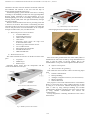
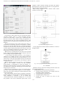
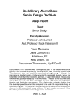
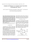
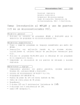
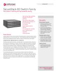
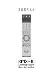
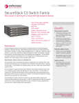
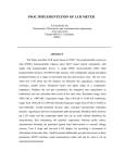
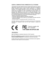
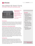
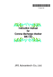
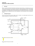
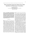
ERANDYA ET AL: WIRELESS RF BASED SURVEILLANCE ROBOT – PNCTM; VOL. 1, JAN 2012 Wireless RF Based Surveillance Robot Controlled via Computer I.E.M.D. Goonethileke and P.K.W. Abeygunawardhana Abstract - Wireless RF based surveillance robot is a robot which can monitor the surrounding environment and provide the feedback to its user. It is equipped with a wireless camera to provide visual aid to the operator. The robot is controlled manually by the user. The specialty here is that user is controlling the robot through a computer via a Graphical User Interface (GUI). Radio Frequency (RF) technology is used as the communication medium between robot and the computer. When the robot meets an obstacle it is sensed by the IR sensors and the robot will alert the user. Then the operator can control the motors appropriately to move around the obstacles to get the needed information. In addition robot can sense the light level. When it is too dark the user will not be able to see clearly through the camera. Therefore the light in the robot will work depending on the light conditions of the surrounding environment. Available surveillance robots in the market have their own control units. Uniqueness in this product is that it can be controlled using a common computer. That also makes this product a cost effective product. Keywords - Wireless Robot, Surveillance Robot, Computer Controlled Robot, Remote Controlled Robot, Spy Robot I. INTRODUCTION There are situations where ground information is priceless, like military operations and rescue operations. For military there is a huge need for a ground vehicle that can spy on enemy grounds. When there is a really severe threat it is not safe to lead the soldiers into those places. Before leading them to that kind of place it is essential to know the details of that place to ensure their safety. Getting information is also helping them to be prepared for the situation ahead. On the other hand there are many places where people cannot go due to various reasons. For example if a person wants to know what is on a ceiling of his house, he has to climb on to the ceiling. But that is not safe and there might be practical issues such the person may not fit in the available space. In the present days many parents are also have problems in keeping eye on their beloved kids while they are busy with work. Therefore there is a need of a baby monitor system. All these problems focus on a common solution that is a surveillance robot which can provide information of its surrounding environment to a remote user. This project contains a robotics based solution to gather information to solve the problems mentioned above. This is a project to build a robot which can provide information about surrounding environment to its user via a computer. This robot has its own camera, to provide visual aid to the user. User can control the robot by using the navigation keys in the GUI. Video of the camera is available to the user by this same GUI. Using this robot, people will be able to get information about the places, without their presence. Army, repair engineers and the parents of the small children are the main target audience of this project. This is a very useful project when it comes to surveillance. Main aim of this project was to provide surveillance facilities to army and the other people who need it. I.E.M.D. Goonethileke was a student at Sri Lanka Institute of Information Technology, New Kandy Road, Malabe, Sri Lanka. She is now with the Electronics Department, Arthur C Clark Institute for Modern Technologies, Katubedda, Moratuwa, Sri Lanka. (e-mail: [email protected]) P. Abeygunawardhana is now with the Research Center and the Department of Electronics and Computer Engineering of Sri Lanka Institute of Information Technology, New Kandy Road, Malabe, Sri Lanka. (e-mail: [email protected]) Objective of this project was to build a robot, which can be used to collect information about people or places remotely by using any common computer. To achieve these objectives following things had to be done, Hardware designing and Implementation Designing and developing the communication and controlling circuits of the robot Developing the mechanical structure of the robot Programming the microcontroller of the robot Developing the Graphical User Interface of the robot(Software Development) Integration Testing the design Final working design II. METHOD This project consists of two main parts Hardware design of the robot Software based remote controller for the robot A. Hardware Design Following figure shows the high level architecture of this robot. Fig. 1. High Level Architecture of the robot As shown in the above diagram, GUI is passing the instructions provided by the user, to the Universal Serial Bus (USB) to Universal Asynchronous Receiver Transmitter (UART) converter and it will pass that to the wireless RF transceiver connected to it. This RF transceiver will then transmit that information to the RF transceiver at the robot end. After receiving the data, RF transceiver at the robot end will pass it to the microcontroller to process. According to the received data, microcontroller will activate or deactivate motors appropriately. In the mean time Infra Red (IR) sensors 123 ERANDYA ET AL: WIRELESS RF BASED SURVEILLANCE ROBOT – PNCTM; VOL. 1, JAN 2012 attached to the robot will sense obstacles around the robot and that feedback will transmit to the user with the help of microcontroller and the RF transceivers. Automated lightning system situated in the robot is working according to the feedback provides from the Light Dependent Resistor (LDR) connected to the microcontroller. At a pre defined lightning level in the surrounding environment, Light Emitting Diode (LED) bulb will light automatically through the microcontroller. Wireless camera attached to the robot is providing visual aid to the user via the GUI. This camera is transmitting the audio and video signals to the receiver at the computer end. Then that receiver will pass those received information to the computer through an Audio Video (AV) to USB converter. Fig. 4. Bottom layer of the robot structure Following figure shows how the robot looks like. 1) Main Components Used in this Robot: Track and Wheel sets Wireless RF transceivers USB to UART converter Gear motors Following figure shows the high level architecture of this robot. Wireless spy camera with the receiver AV to USB converter PIC16F877A microcontroller IR LED and IR sensors LDR and LED bulb 2) Mechanical Structure: This robots mechanical structure can divide into three main parts Top Layer Middle Layer Bottom Layer Following figures shows how the components and the circuits are mounted to each layer Fig. 2. Top layer of the robot structure Fig. 5. Final Design of the robot Most of the time ground robots have either 2WD, 4WD or threaded tracks. This robot is built by using threaded tracks in order to gain the ability of moving steadily. Due to the threaded tracks it can go over both rough and smooth surfaces. B. Software Development 1) Microcontroller Programming: Code inside the microcontroller consists of following major parts USART communication Interrupt handling Analogue to Digital Conversion (A to D conversion) Motor Controlling Obstacle Detection This program is used some inbuilt functions in the MikroC library to control the robot. Light condition detection is done by using A to D conversion. Obstacle detecting part of this robot is done by using Interrupt handling and USART communication. Remote controlling part of this robot is done by using USART communication and wireless RF communication. Activity diagram for controlling mechanism of the robot is shown below. Fig. 3. Middle layer of the robot structure 124 ERANDYA ET AL: WIRELESS RF BASED SURVEILLANCE ROBOT – PNCTM; VOL. 1, JAN 2012 Fig. 8. Activated remote Fig. 6. Activity diagram of the controlling mechanism of the robot 2) GUI Development This GUI is the simple software which developed to control the robot using a computer. This GUI is developed using Visual Basic 6 software (VB6). Following figure shows how the GUI looks like. If the user tries to activate the remote without connecting the RF Transceiver module to the computer it will display a message box saying that “Port Not Found” without activating the above mentioned buttons. If there is no web camera available, this system is displaying a message box by saying “No Web Cam Found” to the user. When “Disconnect Remote” button is clicked by the user, camera and the other command buttons are activated by the “Activate Remote” button will be deactivate. It will also close the port which is opened for the communication between RF Transceiver and the computer. On the click of “Display” button, system will send a message to the operating system to display the video format dialog box to the user. When the user clicks “Camera” button, system will display the video source settings dialogue box to the user. This is also done by using the windows inbuilt messages. On the click of this “System Setting” button, it will show the form which is used to change the settings of the remote controller interface. By using this form user can change the parameters stated below Com Port number Baud rate Data Bits Parity Bits Controller keys Following figure shows the above mentioned form Fig. 7. GUI of the robot Each button on this GUI is reserved for various purposes. When the “Activate Remote” button is clicked once, it will map the web camera into the picture box in the left side corner of the interface. At the same time it will deactivate itself and activate “Disconnect Remote”, “Display” and “Camera” buttons. This button will also open a port for the communication between the RF Transceiver and the computer. Following figure shows the remote controller interface after activating it. 125 ERANDYA ET AL: WIRELESS RF BASED SURVEILLANCE ROBOT – PNCTM; VOL. 1, JAN 2012 computer, remote controller interface will blink the obstacle detected label for three times and will turn to its original state. These are done by using two timers. Basic activity diagram for the software based remote controller is shown below. Fig. 9. System Settings form of the GUI On the click of “Exit” button, user can exit from the remote controller interface. There is a timer associated with this private sub. That timer is used to give a millisecond time period to close the camera before closing the application. If this timer did not exist, the system will produce an error. That happens because of closing of the system before the camera is disabled. When the user focuses on this “Click to Set Focus” button, it will activate the navigation system of the interface. It simply focuses on a text box. When the user is pressing the keys to navigate the robot, those keys will secretly type on this hidden text box. System will pass those data to the com port. User will only see an animation produced by the images hidden in the background, according to the keys they press. When the user is pressing the keys on the text box focused by the “Click to Set Focus” button, a letter will pass to the com port according to the pre defined settings. At the instance the button got focus, it will change its caption as “Use „ASDW‟ for Navi”. This is done to inform the user that he can navigate the robot by using the keys A, S, D, and W keys in the key board. When the user lost the focus from the text box above mentioned key will change its caption to the previous one. When an obstacle is detected by the robot, it is transmitting a signal to the computer. If there are any obstacles, microcontroller is programmed to send the character “x”. When that signal received by the remote controller interface it will indicate it by making the warning sign in the bottom right hand corner in to red color. When there are no obstacles in front or in the back side of the robot, it will transmit another signal (“e”) to the computer. That action will result in turning the “obstacle detected!” label into its original state. Due to the problems with the sensors sometimes it transmits multiple signals. For example when an obstacle detected by the robot sometimes it transmits a set of signals like “xeexexexexexexexex” instead of sending one “x”. To avoid that problem, if the above mentioned signal comes to the Fig. 10. Basic activity diagram of the GUI Activity diagram for obstacle detection indicator is shown in the figure below. Fig. 11. Activity diagram for obstacle indicating system of the GUI III. TESTING Hardware testing is done before making the final circuits and after completing the robot. Testing had been carried in following situations Testing the RF Transceivers to investigate about its functioning and the performance Testing the Motor Controller Circuit Testing the light sensing circuit Testing the code to control the robot via the transmitters 126 ERANDYA ET AL: WIRELESS RF BASED SURVEILLANCE ROBOT – PNCTM; VOL. 1, JAN 2012 To perform these testing a virtual COM Port terminal is used instead of the remote controller interface. PIC simulator IDE software is used to test the code written to drive the robot. PIC Simulator IDE is simulation software which can be used to test hex files. Black box testing methodology is used to test the integrity of the software remote controller. Functions were tested in an end-user perspective to validate the expected functionality. The following test cases were written covering all areas and the results were logged as follows. User can control the robot appropriately to inspect places where they want Robot can detect obstacles and inform the user User is provided with the visual aid to control the robot remotely Robot can maintain the light condition of the surrounding environment to provide constant visual aid to the user This project was highly successful and all the targeted areas were covered and it is functional as expected. TABLE I TEST CASES Test case Ability to connect with the PC webcam and display video on the remote controller interface Disconnect the remote Change display settings Select Webcam feed Change System Settings Exit Navigation controls Expected Result Activate Remote button should automatically locate the default webcam driver of the pc and display Disconnect Remote button should close the webcam driver safely and shutdown the communication port Display button on the controller should open a dialog to select the resolution and color depth The Camera button should open a dialog box to select a webcam and then display the feed on the screen System Settings button on the interface should open a form where the user can define the key values and the port parameters This should disconnect the webcam driver, close the port and exit from the software Click to set focus button should allow the user to navigate the robot by pressing the predefined navigation keys IV. CONCLUTION REFERENCES Actual Result Same as expected [1] [2] [3] [4] Same as expected [5] [6] Same as expected [7] Same as expected Same as expected Same as expected Same as expected This Project was started to develop as a surveillance robot which can be controlled remotely by a personal computer to get the information about people or places in the surrounding environment. As a summery, 127 Dr.Liew Voon Kiong, Visual Basic 6 tutorial, http://www.vbtutor.net/ vb6/vbtutor.html, Created on October 16 1996, Last updated September 29 2011 Accessing Web Cams in Visual Basic 6, http://www.codeproject.com/KB/ vb/webcamcapture.aspx, 11 March 2006 Multimedia Messages, http://msdn.microsoft.com/ens/library/dd743599 (v=VS.85).aspx MikroC User Manual, http://www.mikroe.com/pdf/mikroc/mikroc_ manual.pdf RF Transceiver Selection Guide, http://www.flexipanel.com/Docs/RF% 20Transceiver%20Selection%20Guide%20DS500.pdf, 2 February 2007 PIC16F877A Datasheet,http://ww1.microchip.com/downloads/en/device doc/39582b.pdf L293D atasheet, http://users.ece.utexas.edu/~valvano/Datasheets/ L293d.pdf