1
2/19/2012
HCM IU
Subject: ERTS
Instructor: Ho Trung My
Multi-Tasking and Real-Time
Operating Systems
Ref: Dogan Ibrahim
1
Outline
10.1 State Machines
10.2 The Real-Time Operating System (RTOS)
10.2.1 The Scheduler
10.3 RTOS Services
10.4 Synchronization and Messaging Tools
10.5 CCS PIC C Compiler RTOS
10.5.1 Preparing for RTOS
10.5.2 Declaring a Task
PROJECT 10.1-LEDs
PROJECT 10.2-Random Number Generator
PROJECT 10.3-Voltmeter with RS232 Serial Output
2
1
2/19/2012
Multitasking
• Nearly all microcontroller-based systems perform more
than one activity. For example, a temperature monitoring
system is made up of three tasks that normally repeat
after a short delay, namely:
– Task 1 Reads the temperature
– Task 2 Formats the temperature
– Task 3 Displays the temperature
• More complex systems may have many complex tasks.
In a multi-tasking system, numerous tasks require CPU
time, and since there is only one CPU, some form of
organization and coordination is needed so each task
has the CPU time it needs. In practice, each task takes a
very brief amount of time, so it seems as if all the tasks
are executing in parallel and simultaneously.
3
4
2
2/19/2012
5
6
3
2/19/2012
7
8
4
2/19/2012
9
10
5
2/19/2012
11
12
6
2/19/2012
13
14
7
2/19/2012
RTOS
•
Almost all microcontroller-based systems work in real time. A realtime system is a time responsive system that can respond to its
environment in the shortest possible time.
•
Real time does not necessarily mean the microcontroller should
operate at high speed. What is important in a real-time system is a
fast response time, although high speed can help.
– For example, a real-time microcontroller-based system with various
external switches is expected to respond immediately when a switch is
activated or some other event occurs.
•
A real-time operating system (RTOS) is a piece of code (usually
called the kernel) that controls task allocation when the
microcontroller is operating in a multi-tasking environment. RTOS
decides, for instance, which task to run next, how to coordinate the
task priorities, and how to pass data and messages among tasks.
15
16
8
2/19/2012
17
• This chapter explores the basic principles of multitasking embedded systems and gives examples of an
RTOS used in simple projects. Multi-tasking code and
RTOS are complex and wide topics, and this chapter
describes the concepts pertaining to these tools only
briefly.
• There are several commercially available RTOS systems
for PIC microcontrollers.
– Two popular high-level RTOS systems for PIC microcontrollers
are Salvo (www.pumpkin.com), which can be used from a HiTech PIC C compiler, and
– the CCS (Customer Computer Services) built-in RTOS system.
• In this chapter, the example RTOS projects are based on
the CCS (www.ccsinfo.com) compiler, one of the popular
PIC C compilers developed for the PIC16 and PIC18
series of microcontrollers.
18
9
2/19/2012
10.1 State Machines
•
•
•
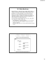
State machines are simple constructs used to perform several
activities, usually in a sequence. Many real-life systems fall into this
category. For example, the operation of a washing machine or a
dishwasher is easily described with a state machine construct.
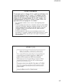
Perhaps the simplest method of implementing a state machine
construct in C is to use a switch-case statement. For example, our
temperature monitoring system has three tasks, named Task 1,
Task 2, and Task 3 as shown in Figure 10.1.
The state machine implementation of the three tasks using switchcase statements is shown in Figure 10.2.
– The starting state is 1, and each task increments the state number by
one to select the next state to be executed.
– The last state selects state 1, and there is a delay at the end of the
switch-case statement.
– The state machine construct is executed continuously inside an endless
for loop.
19
Figure 10.1: State machine implementation
state = 1;
for(;;)
{
switch (state)
{
CASE 1:
// implement TASK 1
state++;
break;
CASE 2:
// i/mplement TASK 2
state++;
break;
CASE 3:
// implement TASK 3
state = 1;
break;
}
delay_ms(n);
}
20
Figure 10.2: State machine implementation in C
10
2/19/2012
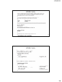
• In many applications, the states need not be executed in
sequence. Rather, the next state is selected by the
present state either directly or based on some condition.
This is shown in Figure 10.3.
• State machines, although easy to implement, are
primitive and have limited application. They can only be
used in systems which are not truly responsive, where
the task activities are well-defined and the tasks are not
prioritized.
• Moreover, some tasks may be more important than
others. We may want some tasks to run whenever they
become eligible. For example, in a manufacturing plant,
a task that sets off an alarm when the temperature is too
hot must be run. This kind of implementation of tasks
requires a sophisticated system like RTOS.
21
state = 1;
for(;;)
{
switch (state)
{
CASE 1:
// implement TASK 1
state = 2;
break;
CASE 2:
// i/mplement TASK 2
state = 3;
break;
CASE 3:
// implement TASK 3
state = 1;
break;
}
delay_ms(n);
}
Figure 10.3: Selecting the next state from the current state
22
11
2/19/2012
10.2 The Real-Time Operating System (RTOS)
•
•
•
•
Real-time operating systems are built around a multi-tasking kernel
which controls the allocation of time slices to tasks. A time slice is the
period of time a given task has for execution before it is stopped and
replaced by another task. This process, also known as context
switching, repeats continuously.
When context switching occurs, the executing task is stopped, the
processor registers are saved in memory, the processor registers of the
next available task are loaded into the CPU, and the new task begins
execution.
An RTOS also provides task-to-task message passing, synchronization
of tasks, and allocation of shared resources to tasks.
The basic parts of an RTOS are:
– Scheduler
– RTOS services
– Synchronization and messaging tools
23
10.2.1 The Scheduler
•
A scheduler is at the heart of every RTOS, as it provides the algorithms
to select the tasks for execution. Three of the more common scheduling
algorithms are:
– Cooperative scheduling
– Round-robin scheduling
– Preemptive scheduling
•
Cooperative scheduling is perhaps the simplest scheduling algorithm
available.
– Each task runs until it is complete and gives up the CPU voluntarily.
– Cooperative scheduling cannot satisfy real-time system needs, since it
cannot support the prioritization of tasks according to importance.
– Also, a single task may use the CPU too long, leaving too little time for other
tasks. And the scheduler has no control of the various tasks’ execution time.
– A state machine construct is a simple form of a cooperative scheduling
technique.
24
12
2/19/2012
Round-robin scheduling
•
•
•
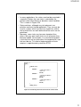
In round-robin scheduling, each task is assigned an equal share of
CPU time (see Figure 10.4).
A counter tracks the time slice for each task. When one task’s time
slice completes, the counter is cleared and the task is placed at the
end of the cycle.
Newly added tasks are placed at the end of the cycle with their
counters cleared to 0. This, like cooperative scheduling, is not very
useful in a real-time system, since very often some tasks take only a
few milliseconds while others require hundreds of milliseconds or
more.
Figure 10.4: Round-robin scheduling
25
Preemptive scheduling
•
•
•
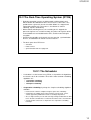
Preemptive scheduling is considered a real-time scheduling
algorithm. It is prioritybased, and each task is given a priority (see
Figure 10.5).
The task with the highest priority gets the CPU time.
Real-time systems generally support priority levels ranging from 0 to
255, where 0 is the highest priority and 255 is the lowest.
Figure 10.5: Preemptive scheduling
26
13
2/19/2012
Mixed scheduling
•
•
•
•
In some real-time systems where more than one task can be at the
same priority level, preemptive scheduling is mixed with round-robin
scheduling.
In such cases, tasks at higher priority levels run before lower priority
ones, and tasks at the same priority level run by round-robin
scheduling.
If a task is preempted by a higher priority task, its run time counter is
saved and then restored when it regains control of the CPU.
In some systems a strict real-time priority class is defined where
tasks above this class may run to completion (or run until a resource
is not available) even if there are other tasks at the same priority
level.
27
Task states
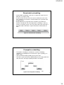
•
In a real-time system a task can be in any one of the following states:
– Ready to run
– Running
– Blocked
Figure 10.6: Task states
28
14
2/19/2012
•
•
•
•
•
When a task is first created, it is usually ready to run and is entered in
the task list. From this state, subject to the scheduling algorithm, the task
can become a running task.
According to the conditions of preemptive scheduling, the task will run if
it is the highest priority task in the system and is not waiting for a
resource.
A running task becomes a blocked task if it needs a resource that is not
available. For example, a task may need data from an A/D converter
and is blocked until it is available. Once the resource can be accessed,
the blocked task becomes a running task if it is the highest priority task
in the system, otherwise it moves to the ready state.
Only a running task can be blocked. A ready task cannot be blocked.
When a task moves from one state to another, the processor saves the
running task’s context in memory, loads the new task’s context from
memory, and then executes the new instructions as required.
29
Task operations
• The kernel usually provides an interface to manipulate
task operations. Typical task operations are:
–
–
–
–
Creating a task
Deleting a task
Changing the priority of a task
Changing the state of a task
30
15
2/19/2012
10.3 RTOS Services
• RTOS services are utilities provided by the kernel that
help developers create real-time tasks efficiently. For
example, a task can use time services to obtain the
current date and time.
• Some of these services are:
–
–
–
–
–
Interrupt handling services
Time services
Device management services
Memory management services
Input-output services
31
10.4 Synchronization and Messaging Tools
• Synchronization and messaging tools are kernel constructs
that help developers create real-time applications.
• Some of these services are:
–
–
–
–
–
Semaphores
Event flags
Mailboxes
Pipes
Message queues
• Semaphores are used to synchronize access to shared
resources, such as common data areas.
• Event flags are used to synchronize the intertask activities.
• Mailboxes, pipes, and message queues are used to send
messages among tasks.
32
16
2/19/2012
10.5 CCS PIC C Compiler RTOS
• The CCS PIC C compiler is one of the popular C compilers for the
PIC16 and PIC18 series of microcontrollers.
• The syntax of the CCS C language is slightly different from that of
the mikroC language, but readers who are familiar with mikroC
should find CCS C easy to use.
• CCS C supports a rudimentary multi-tasking cooperative RTOS
for the PIC18 series of microcontrollers that uses their PCW and
PCWH compilers. This RTOS allows a PIC microcontroller to run
tasks without using interrupts. When a task is scheduled to run,
control of the processor is given to that task. When the task is
complete or does not need the processor any more, control
returns to a dispatch function, which gives control of the processor
to the next scheduled task.
• Because the RTOS does not use interrupts and is not
preemptive, the user must make sure that a task does not run
forever. Further details about the RTOS are available in the
33
compiler’s user manual.
RTOS in CCS C
•
•
•
•
•
•
The CCS language provides the following RTOS functions in addition to
the normal C functions:
rtos_run() initiates the operation of RTOS. All task control operations
are implemented after calling this function.
rtos_terminate() terminates the operation of RTOS. Control returns to
the original program without RTOS. In fact, this function is like a return
from rtos_run().
rtos_enable() receives the name of a task as an argument. The function
enables the task so function rtos_run() can call the task when its time is
due.
rtos_disable() receives the name of a task as an argument. The
function disables the task so it can no longer be called by rtos_run()
unless it is re-enabled by calling rtos_enable().
rtos_ yield() when called from within a task, returns control to the
dispatcher. All tasks should call this function to release the processor so
other tasks can utilize the processor time.
34
17
2/19/2012
•
•
•
•
•
•
•
•
rtos_msg_send() receives a task name and a byte as arguments. The
function sends the byte to the specified task, where it is placed in the task’s
message queue.
rtos_msg_read() reads the byte located in the task’s message queue.
rtos_msg_ poll() returns true if there is data in the task’s message queue.
This function should be called before reading a byte from the task’s
message queue.
rtos_signal() receives a semaphore name and increments that
semaphore.
rtos_wait() receives a semaphore name and waits for the resource
associated with the semaphore to become available. The semaphore count
is then decremented so the task can claim the resource.
rtos_await() receives an expression as an argument, and the task waits
until the expression evaluates to true.
rtos_overrun() receives a task name as an argument, and the function
returns true if that task has overrun its allocated time.
rtos_stats() returns the specified statistics about a specified task. The
statistics can be the minimum and maximum task run times and the total
task run time. The task name and the type of statistics are specified as 35
arguments to the function.
RTOS Setup
#use rtos(timer=X,
[minor_cycle=cycle_time])
− Timer can be any timer available
− Minor_Cycle is rate of fastest task
− Example:
#use rtos(timer=1,
© 2007 Microchip Technology Incorporated. All Rights Reserved.
minor_cycle=50ms)
11028 CCS
Slide
48
36
18
2/19/2012
RTOS Tasks
#task(rate=xxxx,
[max=yyyy],
[queue=z])
− Following function is RTOS task
− Will be called at specified rate
− Max is slowest execution time, used
for budgeting.
− Queue defines RX message size
© 2007 Microchip Technology Incorporated. All Rights Reserved.
11028 CCS
Slide
49
37
RTOS Start and Stop
rtos_run()
− Starts the RTOS
− Will not return until rtos_terminate()
rtos_terminate()
− Stops the RTOS
© 2007 Microchip Technology Incorporated. All Rights Reserved.
11028 CCS
Slide
50
38
19
2/19/2012
#use rtos(timer=1)
#task(rate=100ms, max=5ms)
void TaskInput(void)
{ /* get user input */ }
#task(rate=25ms)
void TaskSystem(void)
{ /* do some stuff
void main(void) {
while(TRUE) {
rtos_run();
sleep();
}
}
© 2007 Microchip Technology Incorporated. All Rights Reserved.
*/ }
11028 CCS
Slide
51
39
RTOS Task Control
rtos_enable(task)
rtos_disable(task)
− Dynamic task control
− Enable/Disable the specified task
− Task is the function name
− All tasks are enabled at start
© 2007 Microchip Technology Incorporated. All Rights Reserved.
11028 CCS
Slide
52
40
20
2/19/2012
RTOS Messaging
rtos_msg_send(task, char)
− Sends char to task
avail=rtos_msg_poll()
− TRUE if a char is waiting for this task
byte=rtos_msg_read()
− Read next char destined for this task
© 2007 Microchip Technology Incorporated. All Rights Reserved.
11028 CCS
Slide
53
41
RTOS Yielding
rtos_yield()
− Stops processing current task
− Returns to this point on next cycle
rtos_await(expression)
− rtos_yield() if expression not TRUE
© 2007 Microchip Technology Incorporated. All Rights Reserved.
11028 CCS
Slide
54
42
21
2/19/2012
#task(rate=100ms, max=5ms)
void TaskInput(void)
{
if (KeyReady())
rtos_msg_send(TaskSystem,
}
KeyGet());
#task(rate=25ms, queue=1)
void TaskSystem(void) {
SystemPrepare();
rtos_await(rtos_msg_poll());
SystemDo(rtos_msg_read());
rtos_yield();
SystemVerify();
}
© 2007 Microchip Technology Incorporated. All Rights Reserved.
11028 CCS
Slide
55
43
RTOS Semaphores
Semaphore
− Determine shared resource availability
− A user defined global variable
− Set to non-zero if used
− Set to zero if free
rtos_wait(semaphore)
− rtos_yield() until semaphore free
− Once free, sets semaphore as used
rtos_signal(semaphore)
− Release semaphore
© 2007 Microchip Technology Incorporated. All Rights Reserved.
11028 CCS
Slide
56
44
22
2/19/2012
RTOS Timing Statistics
overrun=rtos_overrun(task)
− TRUE if task took longer than max
rtos_stats(task, rtos_stats)
− Get timing statistics for specified task
typedef
struct
{
int32
total;
//
total
int16
min;
//
minimum tick
ticks
used by task
int16
max;
//
maximum tick
int16
hns;
//
us = (ticks*hns)/10
time
time
used
used
} rtos_stats;
© 2007 Microchip Technology Incorporated. All Rights Reserved.
11028 CCS
Slide
57
45
RTOS Application Ideas
User I/O
Communication Protocols
© 2007 Microchip Technology Incorporated. All Rights Reserved.
11028 CCS
Slide
58
46
23
2/19/2012
10.5.1 Preparing for RTOS
• In addition to the preceding functions, the #use rtos()
preprocessor command must be specified at the beginning
of the program before calling any of the RTOS functions.
• The format of this preprocessor command is:
#use rtos(timer=n, minor_cycle=m)
where timer is between 0 and 4 and specifies the processor
timer that will be used by the RTOS, and minor_cycle is the
longest time any task will run. The number entered here
must be followed by s, ms, us, or ns.
• In addition, a statistics option can be specified after the
minor_cycle option, in which case the compiler will keep
track of the minimum and maximum processor times the
task uses at each call and the task’s total time used.
47
10.5.2 Declaring a Task
• A task is declared just like any other C function, but tasks in
a multi-tasking application do not have any arguments and
do not return any values. Before a task is declared, a #task
preprocessor command is needed to specify the task
options.
• The format of this preprocessor command is:
#task(rate=n, max=m, queue=p)
– rate specifies how often the task should be called. The number
specified must be followed by s, ms, us, or ns.
– max specifies how much processor time a task will use in one
execution of the task. The time specifed here must be equal to or less
than the time specified by minor_cycle.
– queue is optional and if present specifies the number of bytes to be
reserved for the task to receive messages from other tasks. The
default value is 0.
48
24
2/19/2012
• In the following example, a task called my_ticks is every
20ms and is expected to use no more than 100ms of
processor time.
• This task is specified with no queue option:
#task(rate=20ms, max=100ms)
void my_ticks()
{
...........
...........
}
49
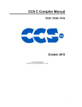
PROJECT 10.1—LEDs
• In the following simple RTOS-based project, four LEDs are
connected to the lower half of PORTB of a PIC18F452-type
microcontroller. The software consists of four tasks, where each
task flashes an LED at a different rate:
– Task 1, called task_B0, flashes the LED
of 250ms.
– Task 2, called task_B1, flashes the LED
of 500ms.
– Task 3, called task_B2, flashes the LED
second.
– Task 4, called task_B3, flashes the LED
every two seconds.
connected to port RB0 at a rate
connected to port RB1 at a rate
connected to port RB2 once a
connected to port RB3 once
• Figure 10.7 shows the circuit diagram of the project. A 4MHz
crystal is used as the clock. PORTB pins RB0–RB3 are
connected to the LEDs through current limiting resistors.
50
25
2/19/2012
The image cannot be display ed. Your computer may not hav e enough memory to open the image, or the image may hav e been corrupted. Restart y our computer, and then open the file again. If the red x still appears, y ou may hav e to delete the image and then insert it again.
Figure 10.7: Circuit diagram of the project
51
•
•
•
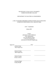
The software is based on the CCS C compiler, and the program listing
(RTOS1.C) is given in Figure 10.8. The main program is at the end of the
program, and inside the main program PORTB pins are declared as outputs
and RTOS is started by calling function rtos_run().
The file that contains CCS RTOS declarations should be included at the
beginning of the program. The preprocessor command #use delay tells the
compiler that we are using a 4MHz clock. Then the RTOS timer is declared as
Timer 0, and minor_cycle time is declared as 10ms using the preprocessor
command #use rtos.
The program consists of four similar tasks:
– task_B0 flashes the LED connected to RB0 at a rate of 250ms. Thus, the LED is
ON for 250ms, then OFF for 250ms, and so on. CCS statement output_toggle is
used to change the state of the LED every time the task is called. In the CCS
compiler PIN_B0 refers to port pin RB0 of the microcontroller.
– task_B1 flashes the LED connected to RB1 at a rate of 500ms as described.
– task_B2 flashes the LED connected to RB2 every second as described.
– Finally, task_B3 flashes the LED connected to RB3 every two seconds as
described.
•
The program given in Figure 10.8 is a multi-tasking program where the LEDs
flash independently of each other and concurrently.
52
26
2/19/2012
RTOS1.c (1/3)
The image cannot be display ed. Your computer may not hav e enough memory to open the image, or the image may hav e been corrupted. Restart y our computer, and then open the file again. If the red x still appears, y ou may hav e to delete the image and then insert it again.
53
RTOS1.c (2/3)
The image cannot be display ed. Your computer may not hav e enough memory to open the image, or the image may hav e been corrupted. Restart y our computer, and then open the file again. If the red x still appears, y ou may hav e to delete the image and then insert it again.
54
27
2/19/2012
RTOS1.c (3/3)
55
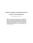
PROJECT 10.2—Random Number Generator
•
•
In this slightly more complex RTOS project, a random number between 0
and 255 is generated. Eight LEDs are connected to PORTB of a
PIC18F452 microcontroller. In addition, a push-button switch is connected
to bit 0 of PORTD (RD0), and an LED is connected to bit 7 of PORTD
(RD7).
Three tasks are used in this project: Live, Generator, and Display.
– Task Live runs every 200ms and flashes the LED on port pin RD7 to indicate
that the system is working.
– Task Generator increments a variable from 0 to 255 continuously and checks
the status of the push-button switch. When the push-button switch is pressed,
the value of the current count is sent to task Display using a messaging
queue.
– Task Display reads the number from the message queue and sends the
received byte to the LEDs connected to PORTB. Thus, the LEDs display a
random pattern every time the push button is pressed.
•
Figure 10.9 shows the project’s block diagram. The circuit diagram is
given in Figure 10.10. The microcontroller is operated from a 4MHz
crystal.
56
28
2/19/2012
The image cannot be display ed. Your computer may not hav e enough memory to open the image, or the image may hav e been corrupted. Restart y our computer, and then open the file again. If the red x still appears, y ou may hav e to delete the image and then insert it again.
Figure 10.9: Block diagram of the project
57
The image cannot be display ed. Your computer may not hav e enough memory to open the image, or the image may hav e been corrupted. Restart y our computer, and then open the file again. If the red x still appears, y ou may hav e to delete the image and then insert it again.
Figure 10.10: Circuit diagram of the project
58
29
2/19/2012
•
•
The program listing of the project (RTOS2.C) is given in Figure 10.11.
The main part of the program is in the later portion, and it configures
PORTB pins as outputs. Also, bit 0 of PORTD is configured as input and
other pins of PORTD are configured as outputs. Timer 0 is used as the
RTOS timer, and the minor_cycle is set to 1s.
The program consists of three tasks:
– Task Live runs every 200ms and flashes the LED connected to port pin RD7.
This LED indicates that the system is working.
– Task Generator runs every millisecond and increments a byte variable called
count continuously. When the push-button switch is pressed, pin 0 of PORTD
(RD0) goes to logic 0. When this happens, the current value of count is sent
to task Display using RTOS function call rtos_msg_send(display, count),
where Display is the name of the task where the message is sent and count
is the byte sent.
– Task Display runs every 10ms. This task checks whether there is a message
in the queue. If so, the message is extracted using RTOS function call
rtos_msg_read(), and the read byte is sent to the LEDs connected to
PORTB. Thus, the LEDs display the binary value of count as the switch is
pressed. The message queue should be checked by using function
rtos_msg_poll(), as trying to read the queue without any bytes in the queue
may freeze the program.
59
TROS2.C (1/4)
60
30
2/19/2012
TROS2.C (2/4)
61
TROS2.C (3/4)
62
31
2/19/2012
TROS2.C (4/4)
63
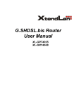
PROJECT 10.3—Voltmeter with RS232 Serial Output
•
In this RTOS project, which is more complex than the preceding ones, the
voltage is read using an A/D converter and then sent over the serial port to a
PC. The project consists of three tasks: Live, Get_voltage, and To_RS232.
– Task Live runs every 200ms and flashes an LED connected to port RD7 of the
microcontroller to indicate that the system is working.
– Task Get_voltage reads channel 0 of the A/D converter where the voltage to be
measured is connected. The read value is formatted and then stored in a
variable. This task runs every two seconds.
– Task To_RS232 reads the formatted voltage and sends it over the RS232 line to
a PC every second.
•
Figure 10.12 shows the block diagram of the project. The circuit diagram is
given in Figure 10.13. A PIC18F8520-type microcontroller with a 10MHz
crystal is used in this project (though any PIC18F-series microcontroller can
be used). The voltage to be measured is connected to analog port AN0 of
the microcontroller. The RS232 TX output of the microcontroller (RC6) is
connected to a MAX232-type RS232-level converter chip and then to the
serial input of a PC (e.g., COM1) using a 9-pin D-type connector. Port pin
RD7 is connected to an LED to indicate whether the project is working.
64
32
2/19/2012
The image cannot be display ed. Your computer may not hav e enough memory to open the image, or the image may hav e been corrupted. Restart y our computer, and then open the file again. If the red x still appears, y ou may hav e to delete the image and then insert it again.
Figure 10.12: Block diagram of the project
65
The image cannot be display ed. Your computer may not hav e enough memory to open the image, or the image may hav e been corrupted. Restart y our computer, and then open the file again. If the red x still appears, y ou may hav e to delete the image and then insert it again.
Figure 10.13: Circuit diagram of the project
66
33
2/19/2012
• In the main part of the program PORTD is configured as
output and all PORTD pins are cleared. Then PORTA is
configured as input (RA0 is the analog input), the
microcontroller’s analog inputs are configured, the A/D clock
is set, and the A/D channel 0 is selected (AN0). The RTOS is
then started by calling function rtos_run().
• The program consists of three tasks:
– Task Live runs every 200ms and flashes an LED connected to port pin
RD7 of the microcontroller to indicate that the project is working.
– Task Get_voltage reads the analog voltage from channel 0 (pin RA0
or AN0) of the microcontroller. The value is then converted into
millivolts by multiplying by 5000 and dividing by 1024 (in a 10-bit A/D
there are 1024 quantization levels, and when working with a reference
voltage of þ5V, each quantization level corresponds to 5000/1024mV).
The voltage is stored in a global variable called Volts.
– Task To_RS232 reads the measured voltage from common variable
Volts and sends it to the RS232 port using the C printf statement. The
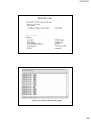
result is sent in the following format:
67
Measured voltage = nnnn mV
RTOS3.C (1/4)
The image cannot be display ed. Your computer may not hav e enough memory to open the image, or the image may hav e been corrupted. Restart y our computer, and then open the file again. If the red x still appears, y ou may hav e to delete the image and then insert it again.
68
34
2/19/2012
RTOS3.C (2/4)
The image cannot be display ed. Your computer may not hav e enough memory to open the image, or the image may hav e been corrupted. Restart y our computer, and then open the file again. If the red x still appears, y ou may hav e to delete the image and then insert it again.
69
RTOS3.C (3/4)
The image cannot be display ed. Your computer may not hav e enough memory to open the image, or the image may hav e been corrupted. Restart y our computer, and then open the file again. If the red x still appears, y ou may hav e to delete the image and then insert it again.
70
35
2/19/2012
RTOS3.C (4/4)
71
Figure 10.15: Typical output from the program
72
36
2/19/2012
Using a Semaphore
• The program given in Figure 10.14 is working and displays the
measured voltage on the PC screen. This program can be
improved slightly by using a semaphore to synchronize the
display of the measured voltage with the A/D samples. The
modified program (RTOS4.C) is given in Figure 10.16. The
operation of the new program is as follows:
– The semaphore variable (sem) is set to 1 at the beginning of the
program.
– Task Get_voltage decrements the semaphore (calls rtos_wait) variable
so that task To_RS232 is blocked (semaphore variable sem = 0) and
cannot send data to the PC. When a new A/D sample is ready, the
semaphore variable is incremented (calls rtos_signal) and task
To_RS232 can continue.
– TaskTo_RS232 then sends the measured voltage to the PC and
increments the semaphore variable to indicate that it had access to the
data. Task Get_voltage can then get a new sample. This process is
73
repeated forever.
RTOS.C (1/4)
74
37
2/19/2012
RTOS.C (2/4)
75
RTOS.C (3/4)
76
38
2/19/2012
RTOS.C (4/4)
77
39