1
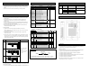
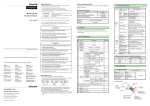
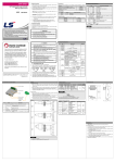
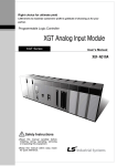
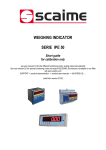
ο Safety Precautions
Before handling the product
► Safety Precautions is for using the product safe and correct in order to prevent the accidents
and danger, so always follow the instructions.
Before using the product, read the datasheet and the User’s manual through to the end carefully
3. Performance Specifications
in order to use the product efficiently.
Item
► The precautions explained here only apply to the MLF-RD04A (Analog Input module). For
No. of input channel
safety precautions on the PLC system, refer to the MasterLogic-50 CPU User’s manual.
► The precautions are divided into 2 sections, ‘Warning’ and ‘Caution’. Each of the meanings is
represented as follows.
MasterLogic-50 Series
Warning
Caution
RTD Input Module
MLF-RD04A
MasterLogic-50 Series User’s Manual
Name
If violated instructions, it can cause death, fatal injury or
Pt100
JIS C1604-1997
type
JPt100
JIS C1604-1981 , KS C1603-1991
Code
Temperature
Pt100
-200 ~ 600℃
input range
JPt100
considerable loss of property.
MasterLogic-50 User’s manual(Programming software)
10310000512
If violated instructions, it can cause a slight injury or slight loss of
MasterLogic-50 Basic Instruction & Programming User’s manual
10310000510
products
Digital output
► The symbols which are indicated in the PLC and User’s Manual mean as follows
This symbol means paying attention because of danger of injury, fire, or malfunction.
Accuracy
This symbol means paying attention because of danger of electrical shock.
Do not contact the terminals while the power is applied.
Protect the product from being gone into by foreign metallic matter.
JPT100
-200.0 ~ 600.0℃
-200.0 ~ 600.0℃
Scaling display
0 ~ 4000
Normal temp.(25℃)
±0.3%
±0.5%
40ms / channel
Non- insulation
Terminal to PLC
Photo-Coupler insulation
Power
RTD (Resistance Temperature Detector) module used in association with CPU module
of MasterLogic-50 series (here in after referred to as MLF-RD04A). The RTD module
convert the input temperature data measured by platinum RTD sensor, PT100 or
JPT100, to signed 16-bit binary data so to output applicable digital value.
I/O points occupied
Fixed type :64 points,Changeable type:16 points
Wiring method
Function
3-wire
Filtering
Digital filter (160 ~ 64000ms)
Alarm
Disconnection detection
Terminal block
Risk of fire, electric shock and malfunction.
July 2007
Caution
module before wiring work.
15 points
Current
DC5V
0.1A
consumption
DC24V
0.1A
Weight
► Be sure to check the rated voltage and terminal arrangement for the
2. General Specifications
630g
Remark
Risk of electric shock, fire and malfunction.
▶ When analog input module is released from the factory, Offset/Gain value is as adjusted for
► Tighten the screw of terminal block with the specified torque range.
10310000850 Printed in Korea
display (unit:0.1)
Full temp.(0~55℃)
Insulation
1. Introduction
Risk of electric shock and malfunction.
►
PT100
Channel to Channel
Warning
10-23-44-07-EN
-200 ~ 600℃
Temperature
Conversion speed
Always forward it to the end user.
►
4 channels
Input sensor
► Store this datasheet in a safe place so that you can take it out and read it whenever necessary.
Installation Manual
Specifications
If the terminal screw looses, it can cause fire and electric shock.
► Use the PLC in an environment that meets the general specifications
contained in this datasheet.
No
Item
1
Operating temp.
0℃∼+55℃
2
Storage temp.
-25℃∼+70℃
3
Specifications
Operating
Standard
respective analog input ranges, which is unavailable for user to change.
4. Part names of functions
5∼95%RH (Non-condensing)
humidity
Risk of electrical shock, fire, erroneous operation and deterioration of the
4
PLC.
Storage humidity
5∼95%RH (Non-condensing)
MLF-RD04A
①
②
For discontinuous vibration
► Be sure that external load does not exceed the rating of output module.
For more information on MasterLogic PLCs , contact your nearest Honeywell office
Australia
Honeywell Ltd.
Phone : (61) 2-9353-7000
Fax : (61) 7-3840-6488
Japan
Honeywell Inc.
Phone: (81) 3-6730-7149
Fax: (81) 3-6730-7228
Philippines
Honeywell Systems (Philippines) Inc.
Phone: (63) 2-633-2830/31
Fax: (63) 2-638-4013
Indonesia
PT Honeywell Indonesia
Phone: (62) 21-535-8833
Fax: (62) 21-536-71008
South Korea
Honeywell Co., Ltd.
Phone : (82) 2-799-6114
Fax : (82) 2-792-9015
Singapore
Honeywell Pte Ltd.
Phone: (65) 6355-2828
Fax: (65) 6445-3033
India
Honeywell Automation India Limited.
Phone: (91) 20-6603-9400
Fax : (91) 20-6603-9800
Malaysia
Honeywell Engineering Sdn Bhd.
Phone: (603) 7958-4988
Fax: (603) 7958-8922
Thailand
Honeywell System (Thailand) Ltd.
Phone: (662) 693-3099
Fax: (662) 693-3085
Taiwan
Honeywell Taiwan Ltd.
Phone : (886) 2-2245-1000
Fax : (62) 2-2245-3243
New Zealand
Honeywell Ltd.
Phone: (64) 9-623-5050
Fax: (64) 9-623-5060
For Countries (SE Asia) Listed below, call
Honeywell Singapore Office
Pakistan, Cambodia, Laos, Myanmar,
Vietnam and East Timor
Frequency
Risk of fire and erroneous operation.
► Do not use the PLC in the environment of direct vibration
5
Risk of electrical shock, fire and erroneous operation.
Vibration
including controllers, recorders, transmitters, actuators, smart sensors, and analytical instruments. To learn more
about these offerings and how they can help your organization achieve breakthrough results, contact your local
► Do not disassemble, repair or modify the PLC.
Risk of electrical shock, fire and erroneous operation.
► When disposing of PLC and battery, treat it as industrial waste.
6
10≤f< 57 ㎐
-
0.035mm
57≤f≤150 ㎐
2
4.9m/s (0.5G)
-
Shocks
► Make sure that the FG terminal is grounded with class 3 grounding which is dedicated to the
7
PLC
Others
PLC
Others
< Best >
< Good >
< Bad >
8
► Connect expansion connector correctly when expansion module are needed,
HFS Asia Pacific
► Do not detach PCB from the case of the module and do not modify the module.
Honeywell Building
► Turn off power when attaching or detaching module.
17 Changin Business Park Central 1
► Cellular phone or walkie-talkie should be farther than 30cm from the PLC
Singapore 486073
www.honeywell.com/ps
10310000850 Printed in Korea
► Input signal and communication line should be farther than minimum 100mm from a high-
Class
/burst
noise
Honeywell Process Solutions
③
Ambient
conditions
IEC61131-2
④
directions)
noise
Fast
Transient
Others
IEC61131-2
directions
* Pulse wave : Sign half-wave pulse
Noise
PLC. Otherwise, it can cause disorder or malfunction of PLC
PLC
X,Y,Z
* Authorized time: 11 ㎳
Radiated electromagnetic field
Italy: 39 02 9214 6503
Latin America: 1-305-805-8188
times in
Acceleration Amplitude
±1,500V
Precautions for use
Canada: 1-800-461-0013
⑤
Each 10
For continuous vibration
Electrostatic discharging
► Do not Install other places except PLC controlled place.
Spain: 34 91313.61.00
-
Square wave impulse noise
France: 33 1 60 19 80 75
Asia/Pacific: 65 6355 2828
0.075mm
(Each 3 times in X,Y,Z
U.S.A.: 1-800-784-3011
Germany: 49 69 8064-336
9.8m/s2(1G)
Number
* Max. impact acceleration: 147 ㎨(15G)
Risk of poisonous pollution or explosion.
Honeywell representative, or contact us at the following phone numbers:
UK: 44 1344 655251
10≤f< 57 ㎐
57≤f≤150 ㎐
Frequency
For Countries Listed below,
call Honeywell India Office
Bangladesh, Nepal, and Sri Lanka
Honeywell offers a complete portfolio of products and solutions for process and machine control applications,
Acceleration Amplitude
Voltage
Voltage : 4kV
IEC61131-2
(contact discharging)
IEC61000-4-2
27 ~ 500MHz, 10 V/m
Power
IEC61131-2
interface
IEC61000-4-4
2kV
No corrosive gas or dust
9
Operating height
2000m or less
10
Pollution degree
2 or less
11
Cooling method
Self-cooling
①
communication
Descriptions
RUN LED
IEC61000-4-3
Digital/Analog I/O
module
No.
IEC61131-2
▶Displays the hardware operation status (Fatal error)
y On
: Normal status
y Flickering : Error(0.2s flickering)
y Off
: hardware error
②
ALM LED
▶ Displays the disconnection status of the channels (Alarm LED)
y On
: Normal status
y Flickering : Disconnection is detected(1s flickering)
y Off
: Operation stop of all channels
③
Terminal block
▶ 3-wire RTD sensors can be connected.
④
▶ Supplies the external DC24V.
⑤
▶ Connects the module with an expansion module.
1 kV
External power terminal
tension line and a power line in order not to be affected by noise and magnetic field.
Expansion connector
5. Handling precaution
7. Configuration of internal memory
1) Do not drop or impact the product.
2) Do not detach PCB from the case, it may cause malfunction.
3) During wiring or other work, do not allow any wire chips get inside the product.
4) Switch the external power off before mounting or removing the module and the
cable.
5) Be sure to turn the drive device off for detaching or inserting the cable
6. Wiring
6.1 Precautions for wiring
1) Don’t let AC power line near to analog output module’s external output signal
line. With an enough distance kept away between, it will be free from surge or
inductive noise.
2) Cable shall be selected in due consideration of ambient temperature and
allowable current, whose size is not less than the max. cable standard of
AWG22 (0.3㎟).
3) Don’t let the cable too close to hot device and material or in direct contact with
oil for long, which will cause damage or abnormal operation due to short-circuit.
4) Check the polarity when wiring the terminal.
5) Wiring with high-voltage line or power line may produce inductive hindrance
causing abnormal operation or defect.
8. Disconnection information
7.1 U area of RTD module
Device
assignment
Descriptions
Uxy.00.E
Module H/W Error
Uxy.00.F
Module Ready
Uxy.01.0
Channel 0 Operation Flag
Uxy.01.1
Channel 1 Operation Flag
Uxy.01.2
Signal
Direction
R/W
Address
(Dec)
R
RTD→ CPU
R
RTD→ CPU
Error code
Description
0
Normal operation
1
A line disconnection
Channel 2 Operation Flag
2
B line disconnection
Uxy.01.3
Channel 3 Operation Flag
3
A line/B line disconnection
Uxy.01.4
Channel 0 Disconnection Flag
Uxy.01.5
Channel 1 Disconnection Flag
Uxy.01.6
Channel 2 Disconnection Flag
Uxy.01.7
Channel 3 Disconnection Flag
Uxy.01.8
Channel 0 Setting Error
Uxy.01.9
Channel 1 Setting Error
Uxy.01.A
Channel 2 Setting Error
Uxy.01.B
68 ~ 71
Channel 0 Measured Temperature
Uxy.05
Channel 1 Measured Temperature
Uxy.06
Channel 2 Measured Temperature
Uxy.07
Channel 3 Measured Temperature
Uxy.08
Channel 0 Scaled Value
Uxy.09
Channel 1 Scaled Value
Uxy.10
Channel 2 Scaled Value
Uxy.11
Channel 3 Scaled Value
ALM LED Off
ALM LED 1s flickering
9. Dimensions
Unit: mm
Channel 3 Setting Error
Uxy.04
Remark
R
RTD→ CPU
R
RTD→ CPU
MLF-RD04A
6.2 Wiring examples
1) 3 types of sensor connecting methods are available (2, 3 and 4-wire)
Used an identical type of wire (thickness, length, etc) for each 3 wire when
extended lead wire is used
R/W
0
R/W
0
R/W
0
R/W
0
R/W
Reserved
0
R/W
Scaling enable
0
R/W
-32768
R/W
-
R
0
Channel enable
1H
1
Channel 0 Sensor Type
2H
2
Channel 1Sensor Type
3H
3
Channel 2 Sensor Type
4H
4
Channel 3 Sensor Type
5H
5
Temperature Display Unit
6H
6
Channel 0 Filter Value
7H
7
Channel 1 Filter Value
8H
8
Channel 2 Filter Value
9H
9
Channel 3 Filter Value
AH~11H
10~17
12H
18
A
13H~43H
19~67
B
44H
68
Channel 0 Disconnection Information (code)
b
45H
69
Channel 1 Disconnection Information (code)
46H
70
Channel 2 Disconnection Information (code)
47H
71
Channel 3 Disconnection Information (code)
the wire directly to the terminal block of MLF-RD4A without connection
terminal unit. If a connection terminal is to be used, compensating wire shall
be connected as shown below.
Wiring examples
Disconnection
2*
Initial
0H
3) Length of wire is to be as short as possible and it is recommended to connect
1*
Description
Dec
If will cause an error.)
2-wire
Address
Hex
2) The resistance of each conductor is to be less than 10Ω. (If lager than this,
Method
7.2 Parameter area of RTD module
FG
Reserved
Remark
PUT/GET
10. Warranty
1) Warranty period
Honeywell provides a 12-month-warranty for new MasterLogic PLC systems and
90-day-warranty for spare parts from the date of delivery.
1.When the channel is enabled
- Disconnection detection
A
B
3-wire
b
1*
2*
FG
enabled.
2. When the channel is disabled
How to use U device
- Disconnection detection
disabled.
2) Warranty conditions
For any defects of the product within the warranty period, Honeywell will replace
or repair the defective parts free of charge except the following cases:
Remark
Base No.
Slot No.
Uxy.00.0
Bit No.
Word No.
Ex1) When reading “CH0 Active” bit of Base 1, Slot 6 module
A
B
4wire
b
1*
2*
FG
*1: Let the terminals B and b short on the terminal block of the module if 2-wired
sensor is to be connected.
*2: If sensor and compensating wire are shielded, shield line can be connected to FG.
-> U16.01.0
Ex2) When reading “CH0 Active” bit of Base 0, Slot 11 module -> U0B.01.0
a) The defects caused by improper condition, environment or operation
b) The defects caused by external devices.
c) The defects caused by redesigning or repairing based on user’s own discretion.
d) The defects caused by improper usage of the product.
e) The defects caused by natural disaster.
3) This warranty is limited to the PLC component only. It is not valid for the other
related system which the PLC is attached to.