1
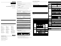
Before handling the product
DATASHEET
o Safety Precautions
Before using the product, read the datasheet and the User’s manual through to the end carefully in
► Safety Precautions is for using the product safe and correct in order to prevent the accidents and
order to use the product efficiently.
Performance specifications of A/D conversion module are as specified in Table
danger, so please go by them.
► The precautions explained here only apply to the 2MLF-AD4S unit. For safety precautions on the
► The precautions are divided into 2 sections, ‘Warning’ and ‘Caution’. Each of the meanings is
MasterLogic-200
represented as follows.
Analog Input Module (Isolated type)
Warning
If violated instructions, it can cause death, fatal injury or considerable
Caution
If violated instructions, it can cause a slight injury or slight loss of
Specifications
Item
Voltage input
MasterLogic-200 Series User’s Manual
PLC system, refer to the MasterLogic-200 CPU manual.
2MLF-AD4S
3. Performance Specifications
Name
Code
MasterLogic-200 User’s manual(Programming software)
MasterLogic-200 Basic Instruction & Programming User’s manual
10310000512
10310000510
Analog input
loss of property.
Analog input
range setting
products
► The symbols which are indicated in the PLC and User’s Manual mean as follows
Analog input
Gives warnings and cautions to prevent from risk of injury, fire, or malfunction
Digital output
Signed Value
Gives warnings and cautions to prevent from risk of electrical shock.
Precise Value
► Store this datasheet in a safe place so that you can take out and read whenever necessary. Always
►
Digital output
►
Do not contact the terminals while the power is applied.
Protect the product from being gone into by foreign metallic matter.
A/D conversion module designed for MasterLogic-200 series is used to convert analog
signal (voltage or current input) to the digital value of signed 16-bit binary data specified in
PLC CPU.
Risk of fire, electric shock and malfunction.
The max.
resolution
Caution
► Be sure to check the rated voltage and terminal arrangement for the
module before wiring work.
10310000714 Printed in Korea
2. General Specifications
► Tighten the screw of terminal block with the specified torque range.
If the terminal screw looses, it can cause fire and electric shock.
► Use the PLC in an environment that meets the general specifications
contained in this datasheet.
No
Item
Specifications
1
2
Operating temp.
Storage temp.
Operating
humidity
Storage humidity
0℃∼+55℃
-25℃∼+70℃
3
4
Risk of electrical shock, fire, erroneous operation and deterioration of the PLC.
► Be sure that external load does not exceed the rating of output module.
Risk of fire and erroneous operation.
5
For more information on MasterLogic PLCs , contact your nearest Honeywell office
Vibration
► Do not use the PLC in the environment of direct vibration
Risk of electrical shock, fire and erroneous operation.
Australia
Honeywell Ltd.
Phone : (61) 2-9353-4500
Fax : (61) 2-9353-7677
Japan
Honeywell Inc.
Phone: (81)3-5440-1395
Fax: (81)3-5440-1368
Singapore
Honeywell Pte Ltd.
Phone: (65) 6355-2828
Fax: (65) 6445-3033
► Do not disassemble, repair or modify the PLC.
China
Honeywell (Tianjin) Ltd. – Beijing
Phone: (86-10) 8458-3280
Fax: (86-10) 8458-3102
South Korea
Honeywell Co., Ltd.
Phone : (82) 2-799-6114
Fax : (82) 2-792-9015
Thailand
Honeywell Systems Ltd.
Phone: (662) 693-3099
Fax: (662) 693-3085
► When disposing of PLC and battery, treat it as industrial waste.
Honeywell (Tianjin) Ltd. – Shanghai
Phone: (86-21) 6237-0237
Fax : (86-21) 6237-3102
Malaysia
Honeywell Engineering Sdn Bhd.
Phone: (603) 7958-4988
Fax: (603) 7958-8922
Taiwan
Honeywell Taiwan Ltd.
Phone: (886) 2-2245-1000
Fax: (886) 2-2245-3241
New Zealand
Honeywell Ltd.
Phone: (64-9) 623-5050
Fax: (64-9) 623-5060
For Countries (SE Asia) Listed
below, call Honeywell Singapore
Office
Pakistan, Cambodia, Laos,
Myanmar, Vietnam and East Timor
Indonesia
PT Honeywell Indonesia
Phone : (62) 21-535-8833
Fax : (62) 21-5367-1008
India
Honeywell Automation India Ltd.
Phone: (91) 20-5603-9400
Fax: (91) 20-5603-9800
Philippines
Honeywell Systems Inc.
Phone: (63-2) 633-2830
Fax: (63-2) 638-4013
For Countries Listed below,
call Honeywell India Office
Bangladesh, Nepal, and Sri Lanka
Risk of electrical shock, fire and erroneous operation.
Precautions for use
7
► Do not Install other places except PLC controlled place.
17F, Kukje Center Building, 191 Hangangro-2ga,
Yongsan-gu, Seoul 140-702, Korea
Tel : 82-2-799-6114 / Fax : 82-2-792-9015
Email: MasterLogic_support @Honeywell.com
10310000714 Printed in Korea
Noise
PLC. Otherwise, it can cause disorder or malfunction of PLC
Others
PLC
Others
< Good >
PLC
Others
< Bad >
► Connect expansion connector correctly when expansion module are needed,
Honeywell Process Solutions
Shocks
► Make sure that the FG terminal is grounded with class 3 grounding which is dedicated to the
< Best >
Honeywell Co., Ltd.
6
Risk of poisonous pollution or explosion.
PLC
Accuracy
General specifications of MasterLogic-200 series are as specified in Table
Risk of electric shock, fire and malfunction
► Do not detach PCB from the case of the module and do not modify the module.
► Turn off power when attaching or detaching module.
► Cellular phone or walkie-talkie should be farther than 30cm from the PLC
► Input signal and communication line should be farther than minimum 100mm from a high-tension
line and a power line in order not to be affected by noise and magnetic field.
0~5V
Ambient
conditions
9 Operating height
10 Pollution degree
11 Cooling method
8
Standard
Max. conversion
speed
Absolute max.
input
Analog
input points
5∼95%RH (Non-condensing)
5∼95%RH (Non-condensing)
For discontinuous vibration
Frequency Acceleration
Amplitude
Number
10≤f< 57㎐
0.075mm
57≤f≤150㎐ 9.8m/s2(1G)
Each 10
For continuous vibration
times in
X,Y,Z
Frequency Acceleration
Amplitude
directions
10≤f< 57㎐
0.035mm
57≤f≤150㎐ 4.9m/s2(0.5G)
* Max. impact acceleration:147㎨(15G)
* Authorized time :11㎳
* Pulse wave : Sign half-wave pulse (Each 3 times in X,Y,Z
directions)
Square wave impulse noise
±1,500V
Voltage : 4kV(contact
Electrostatic discharging
discharging)
Radiated electromagnetic field
27 ~ 500MHz, 10 V/m
noise
Fast
Power
Digital/Analog I/O
Class
Transient
module communication interface
/burst
Voltage
2kV
1 kV
noise
No corrosive gas or dust
2000m or less
2 or less
Self-cooling
IEC61131-2
-10 ~ 10 V
-32000 ~ 32000
1000 ~
5000
0 ~ 5000
0 ~ 10000
-10000 ~
10000
0 ~ 10000
(2) Current Type
1~5V
62.5 ㎶
0~5V
78.1 ㎶
0 ~ 10 V
156.3 ㎶
-10 ~ 10 V
312.5 ㎶
Terminal
connected
I/O points
occupied
Internalconsumed current
Weight
4 ~ 20 mA
250 ㎁
0 ~ 20 mA
312.5 ㎁
±0.05% (when ambient temperature is 25 ℃ ±5℃)
Temperature coefficient: ±40ppm/℃ (0.0040 %/℃)
10㎳/ channel
±15 V
±30 mA
4 channels
Between channels
Insulation method
IEC61131-2
0 ~ 10 V
Analog input
4 ~ 20 mA
0 ~ 20 mA
Digital output
Signed Value
-32000 ~ 32000
Precise Value
4000 ~ 20000
0 ~ 20000
Percentile Value
0 ~ 10000
► 16-bit binary value
► Format of digital output data can be set through user program or S/W package
respectively based on channels.
Analog input range Resolution (1/64000) Analog input range Resolution (1/64000)
1. Introduction
Risk of electric shock and malfunction
1~5V
Percentile Value
forward it to the end user.
Warning
Current input
DC 1 ∼ 5 V
DC 4 ∼ 20 mA
DC 0 ∼ 5 V
DC 0 ∼ 10 V
DC 0 ~ 20 mA
DC -10 ∼ 10 V
(Input Resistance 250 Ω)
(Input Resistance: 1 MΩ min.)
► Analog input range can be selected through user program or Software package.
(When using the current input the terminal V+ and I+ should be shorted)
► Respective input ranges can be set based on channels.
(1) Voltage Type
Between terminal –
PLC power supply
Isolation (Trans)
Isolation (Photo-Coupler)
18-point terminal
Fixed point assignment: 64 , Variable point assignment : 16
DC 5 V: 610㎃
140g
Notes
▶ When A/D conversion module is released from the factory, Offset/Gain value is as adjusted for
respective analog input ranges, which is unavailable for user to change.
IEC61131-2
IEC61000-4-2
IEC61131-2,
IEC61000-4-3
IEC61131-2
IEC61000-4-4
6.2 Wiring Example
4. Part names of functions
Address
1) Voltage input
Part names of functions are as described below
CH0
+
-
*1
CH3
-
R
UXY.10.0
UXY.10.1
UXY.10.2
UXY.10.3
Flag to detect CH0 disconnection (1 ~ 5 V or 4 ~ 20 mA)
Flag to detect CH1 disconnection (1 ~ 5 V or 4 ~ 20 mA)
Flag to detect CH2 disconnection (1 ~ 5 V or 4 ~ 20 mA)
Flag to detect CH3 disconnection (1 ~ 5 V or 4 ~ 20 mA)
R
UXY.11.0
Flag to request error clear
R
*2
*3
R
I3+
COM3
*1
Ch0 high alarm of change rate (H)
Ch0 low alarm of change rate (L)
Ch1 high alarm of change rate (H)
Ch1 low alarm of change rate (L)
Ch2 high alarm of change rate (H)
Ch2 low alarm of change rate (L)
Ch3 high alarm of change rate (H)
Ch3 low alarm of change rate (L)
R
V3+
+
UXY.09.0
UXY.09.1
UXY.09.2
UXY.09.3
UXY.09.4
UXY.09.5
UXY.09.6
UXY.09.7
I0+
COM0
R
R
③
2) Current input
V0+
*4
CH0
+
No
①
Name
RUN LED
Descriptions
▶ Displays the operation status
On: Operation normal
Blinks(0.2s): Error occurs (Refer to 2MLF-AD4S user’s manual)
Off: DC 5V disconnected, module error
②
ALM LED
▶Displays the alarm status
Blinks: Alarm (Processing alarm, Change rate alarm) detected
Off: Operation normal
③
Terminal
▶ Analog input terminal, whose respective channels can be connected
with external devices.
-
-
CH3
*1
R
V3+
*4
+
I0+
COM0
*1
*2
R
Address
R
Hex
0H
1H
2H
3H
4H
5H
6H
7H
8H
9H
0
1
2
3
4
5
6
7
8
9
AH
10
Ch0 high value of processing alarm (H)
BH
CH
DH
EH
FH
10H
11H
12H
13H
14H
15H
16H
17H
18H
11
12
13
14
15
16
17
18
19
20
21
22
23
24
Ch0 low value of processing alarm (L)
Ch0 low-low value of processing alarm (LL)
Ch1 high-high value of processing alarm (HH)
Ch1 high value of processing alarm (H)
Ch1 low value of processing alarm (L)
Ch1 low-low value of processing alarm (LL)
Ch2 high-high value of processing alarm (HH)
Ch2 high value of processing alarm (H)
Ch2 low value of processing alarm (L)
Ch2 low-low value of processing alarm (LL)
Ch3 high-high value of processing alarm (HH)
Ch3 high value of processing alarm (H)
Ch3 low value of processing alarm (L)
Ch3 low-low value of processing alarm (LL)
R/W
19H
1AH
25
Period of ch0 change rate
26
Period of ch1 change rate
R
1BH
27
Period of ch2 change rate
1CH
28
Period of ch3 change rate
1DH
29
High limit of ch0 change rate
1EH
30
Low limit of ch0 change rate
standard.
*2) The Input resistance voltage input is 250 Ω (typ.).
*3) The Input resistance current input is 1 MΩ (min.).
*4) When using the current input, short the V+ terminal and I+ terminal.
5. Handling precaution
1) Do not drop or impact the product.
2) Do not detach PCB from the case, it may cause malfunction.
3) During wiring or other work, do not allow any wire chips get inside the product.
4) Switch the external power off before mounting or removing the module and the
cable.
7. Configuration of internal memory
7.1 I/O area of A/D converted data
6. Wiring
6.1 Precautions for wiring
1) Don’t let AC power line near to analog input module’s external input signal
line. With an enough distance kept away between, it will be free from surge or
inductive noise.
2) Cable shall be selected in due consideration of ambient temperature and
allowable current, whose size is not less than the max. cable standard of
AWG22 (0.3㎟).
3) Don’t let the cable too close to hot device and material or in direct contact with
oil for long, which will cause damage or abnormal operation due to short-circuit.
4) Check the polarity when wiring the terminal.
5) Wiring with high-voltage line or power line may produce inductive hindrance
causing abnormal operation or defect.
Description
Description
Dec
*1) Use the cable of 2-core twisted shield. AWG 22 is recommended for the cable
Address
R
W
7.2 A/D Setting area of Run parameters
R
Channel enable/disable
Input range selection
Digital output type selection
Filter process enable/disable
CH0 filter constant
CH1 filter constant
CH2 filter constant
CH3 filter constant
Alarm enable/disable (Processing/Change rate)
Ch0 high-high value of processing alarm (HH)
UXY.00.0
UXY.00.F
H/W error
Module ready
UXY.01.0
UXY.01.1
UXY.01.2
UXY.01.3
Ch0 run flag
Ch1 run flag
Ch2 run flag
Ch3 run flag
R
1FH
31
High limit of ch1 change rate
UXY.02
CH0 digital output value
R
20H
32
Low limit of ch1 change rate
UXY.03
CH1 digital output value
R
21H
33
High limit of ch2 change rate
UXY.04
CH2 digital output value
R
22H
34
Low limit of ch2 change rate
UXY.05
CH03digital output value
R
23H
35
High limit of ch3 change rate
UXY.06
Reserved
R
UXY.07
Reserved
R
24H
25H
36
37
Low limit of ch3 change rate
Error code
8. Dimensions
Unit : ㎜
*3
I3+
COM3
R/W
Ch0 high-high processing alarm (HH)
Ch0 high processing alarm (H)
Ch0 low processing alarm (L)
Ch0 low-low processing alarm (LL)
Ch1 high-high processing alarm (HH)
Ch1 high processing alarm (H)
Ch1 low processing alarm (L)
Ch1 low-low processing alarm (LL)
Ch2 high-high processing alarm (HH)
Ch2 high processing alarm (H)
Ch2 low processing alarm (L)
Ch2 low-low processing alarm (LL)
Ch3 high-high processing alarm (HH)
Ch3 high processing alarm (H)
Ch3 low processing alarm (L)
Ch3 low-low processing alarm (LL)
R
V0+
①
②
Description
UXY.08.0
UXY.08.1
UXY.08.2
UXY.08.3
UXY.08.4
UXY.08.5
UXY.08.6
UXY.08.7
UXY.08.8
UXY.08.9
UXY.08.A
UXY.08.B
UXY.08.C
UXY.08.D
UXY.08.E
UXY.08.F
R/W
Remark
R/W
R/W
R/W
R/W
PUT
PUT
PUT
PUT
R/W
PUT
R/W
PUT
R/W
R/W
PUT
PUT
R/W
PUT
R/W
PUT
R/W
PUT
R/W
PUT