1
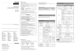
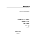
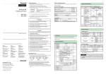
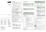
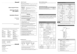
DATASHEET Safety Precautions Before handling the product ► Safety Precautions is for using the product safe and correct in order to prevent the accidents and Before using the product, read the datasheet and the User’s manual through to the end carefully in 3. Performance Specifications order to use the product efficiently. danger, so always follow the instructions. Performance specifications of D/A conversion module are as specified below. ► The precautions explained here only apply to each module. For safety precautions on the PLC Specification system, refer to the MasterLogic-200 User’s manual. Item ► The precautions are divided into 2 sections, ‘Warning’ and ‘Caution’. Each of the meanings is represented as follows. MasterLogic-200 Warning Caution DA Conver. 2MLF-DV4A 2MLF-DV8A 2MLF-DC8A Analog output 1. Introduction Gives warning and cautions to prevent from risk of electrical shock D/A conversion module designed for MasterLogic-200 series is used to convert the digital value of signed 16-bit binary data (data: 14 bits) specified in MasterLogic-200 CPU to analog signal (voltage or current output). package respectively based on channels. 1 ~ 5V Do not contact the terminals while the power is applied. Digital input not drop or insert any metallic object into the product. Caution terminal arrangement for the module before wiring work. Item 0℃∼+55℃ Signed Value Storage temp. -25℃∼+70℃ Precise Value Process Solutions Location Organization United States and Canada Honeywell IAC Solution Support Center 1-800-822-7673 Europe Honeywell TAC-EMEA +32-2-728-2704 Pacific India Honeywell Global TAC – Pacific Honeywell Global TAC – India +91-20-2682-2458 People’s Republic of China Singapore Honeywell Global TAC – Korea Honeywell Global TAC – China +82-2-799-6317 6 Risk of electrical shock, fire and erroneous operation Shocks Taiwan Honeywell Global TAC – Taiwan +886-7-323-5900 Japan Honeywell Global TAC – Japan +81-3-5440-1303 Elsewhere Call your nearest Honeywell office. Honeywell International Process Solutions 2500 West Union Hills Phoenix, AZ 85027 1-800 343-0228 9.8m/s (1G) times in Amplitude X,Y,Z - 0.035mm directions 2 - 7 field noise Fast Transient /burst noise PLC Others 8 < Good > 0~5 V 0.3125 ㎷ 0~10 V 0.625 ㎷ ±10 V 1.250 ㎷ IEC61131-2 < Bad > 9 ► Connect expansion connector correctly when expansion modules are needed. ► Do not detach PCB from the case of the module and do not modify the module. ► Turn off the power when attaching or detaching module. ► Cellular phone or walkie-talkie should be farther than 30cm from the PLC ► Input signal and communication line should be farther than minimum 100mm from a high-tension line and a power line in order not to be affected by noise and magnetic field. Ambient conditions Operating height 10 Pollution degree 11 Cooling method Class Voltage Max. conversion input output Voltage : 4Kv (contact discharging) 27 ~ 500MHz, 10 V/m Power Digital/Analog I/O module communication interface 2kV 1 kV ±24 ㎃ 4ch/1module 8ch/1module Photo-coupler insulation between input terminal and PLC power (no insulation between channels) 18-point terminal connected IEC61131-2 IEC61000-4-2 IEC61131-2, IEC61000-4-3 I/O Occupied points DC5V consumed current DC24V consumed current IEC61131-2 Weight 1.25 ㎂ ±15 V Terminal ±1,500V 0~20 ㎃ 250㎲/Ch speed Insulation method 1 .0 ㎂ ±0.2% or less (when ambient temperature is 25℃) Absolute max. IEC61131-2 4~20 ㎃ ±0.3% or less (when ambient temperature is 0 ℃ ~ 55 ℃) Analog * Pulse wave : Sign half-wave pulse Noise Otherwise, it may cause disorder or malfunction of PLC Others resolution output points * Authorized time: 11㎳ Electrostatic discharging ► Do not install in any places other than PLC controlled place. < Best > Each 10 Acceleration Radiated electromagnetic Precautions for use PLC - (Each 3 times in X,Y,Z directions) Risk of poisonous pollution or explosion Others 0.250 ㎷ Accuracy For continuous vibration Square wave impulse noise ► When disposing of PLC and battery, treat it as industrial waste. PLC +65-6580-3500 57≤f≤150㎐ ► Do not disassemble, repair or modify the PLC. +86-10-8458-3280 ext. 361 Honeywell Global TAC – South East Asia 0.075mm 57≤f≤150㎐ 4.9m/s (0.5G) ► Ensure that the FG terminal is grounded with class 3 grounding which is dedicated to the PLC. Korea 1~5 V Number * Max. impact acceleration: 147㎨(15G) Risk of electrical shock, fire and erroneous operation 1300-300-4822 (toll free within Australia) +61-8-9362-9559 (outside Australia) - 10≤f< 57㎐ ► Do not use the PLC in the environment of direct vibration Phone Amplitude 2 Frequency Risk of fire and erroneous operation Telephone Contact us by telephone at the numbers listed below. Acceleration 10≤f< 57㎐ ► Be sure that external load does not exceed the rating of output module. 0 ~ 20000 0 ~ 10000 The max. For discontinuous vibration Risk of electrical shock, fire, erroneous operation and deterioration of the PLC http://www.honeywell.com/ps 5∼95%RH (Non-condensing) humidity specifications contained in this datasheet. -8000 ~ 8000 4000 ~ 20000 1/16000 Storage Vibration 0 ~ 20mA 5∼95%RH (Non-condensing) humidity Frequency 5 10000~10000 0 ~ 16000 Percentile Value Operating Risk of fire and electric shock if the terminal screw looses. WWW Address (URL) 4 ~ 20mA Operating temp. 4 0~10000 0 ~ 10000 Unsigned Value 2 ► Tighten the screw of terminal block with the specified torque range. http://www.honeywell.com Percentile Value 1 Risk of electric shock, fire and malfunction ► Use the PLC in an environment that meets the general 0~5000 Specifications specifications 3 ► Before wiring the PLC, ensure to check the rated voltage and Honeywell Organization 1000~5000 General specifications of MasterLogic-200 series are as specified below. No -10 ~ 10V -8000 ~ 8000 Precise Value Related not charge, heat, short, solder and break up the battery. 0 ~ 10V 0 ~ 16000 Signed Value 2. General specifications 1 Corporate 0 ~ 5V Unsigned Value Risk of injury and fire by explosion and ignition. World Wide Web The following Honeywell web sites may be of interest to Process Solution customers. :550Ω or less ► Format of digital output data can be set through user program or S/W Risk of fire, electric shock and malfunction. Contacts Load resistance :600Ω or less ► 16-bit binary value (data: 14 bits) Risk of electric shock and malfunction. 10310000594 Printed in Korea Load resistance Respective input ranges can be set based on channels. Warning Do DC -10 ~ 10V package. Always forward it to the end user. Do DC 4 ~ 20㎃, DC 0 ~ 20㎃ Load resistance : 1㏀ or more Analog output range can be selected through user program or Software ► Store this datasheet in a safe place so that you can take out and read whenever necessary. 2MLF -DC8A (Current output) DC 0 ~ 10V If violated instructions, it may cause a slight injury or slight loss of ► The symbols which are indicated in the PLC and User’s Manual mean as follows 2MLF-DC4A 2MLF -DC4A (Current output) DC 0 ~ 5V loss of property. Gives warning and cautions to prevent from risk of injury, fire, or malfunction 2MLF -DV8A (Voltage output) DC 1 ~ 5V If violated instructions, it may cause death, fatal injury or considerable products 2MLF-DV4A (Voltage output) Fixed point assignment:: 64, Variable point assignment:16 190 ㎃ 190 ㎃ 190 ㎃ 190 ㎃ 140 ㎃ 180 ㎃ 210 ㎃ 300 ㎃ 135g 155g 137g 150g IEC61000-4-4 Note No corrosive gas or dust ▶ Please use DC24V/1A for the external power supply. ▶ Offset/Gain value is fixed and can not be changed by user. 2000m or less 2 or less Self-cooling 6.2 Wiring example Motor drive module 2MLF-DV4A/DV8A 2MLF-DV8A 2MLF-DC4A D/A conversion circuit 2MLF-DC8A ① 1㏀~ 1㏁ Device (2MLK) GND Motor drive module *3 ② CH 7 *1 7 8 1㏀~ 1㏁ -12V AGND ② AGND External power supply (DC24V) : Pin17~18 CH5 Error _xy_CH1_ACT CH1 Active Uxy.01.2 _xy_CH2_ACT CH2 Active Uxy.01.3 _xy_CH3_ACT CH3 Active Uxy.01.4 _xy_CH4_ACT CH4 Active*1 Uxy.01.5 _xy_CH5_ACT CH5 Active *1 Uxy.01.6 _xy_CH6_ACT CH6 Active*1 Uxy.01.7 _xy_CH7_ACT CH7 Active Uxy.02 _xy_OUTEN Output status setting Uxy.03 _xy_CH0_DATA Ch0 input Uxy.04 _xy_CH1_DATA Ch1 input Uxy.05 _xy_CH2_DATA Ch2 input Uxy.06 _xy_CH3_DATA Ch3 input Uxy.07 _xy_CH4_DATA Ch4 input *1 Uxy.08 _xy_CH5_DATA Ch5 input *1 Uxy.09 _xy_CH6_DATA Ch6 input *1 Uxy.10 _xy_CH7_DATA Ch7 input *1 *2 *1 Motor drive module *1 *2 600Ω or less DC 24V 0V R/W R Uxy.01.1 GND DC/DC conversion circuit _xy_CH5_ERR Module Ready +18V -12V CH4 Error Uxy.00.5 CH0 Active 7 8 devices. _xy_CH4_ERR _xy_CH0_ACT 600Ω or less 17 18 CH3 Error Uxy.00.4 Uxy.01.0 *3 Analog input terminal, whose respective channels can be connected with external _xy_CH3_ERR CH7 Error CH 7 Terminal CH2 Error Uxy.00.3 _xy_RDY GND Off: Module error _xy_CH2_ERR Uxy.00.F Description Blinks: Error occurs (Refer to user’s manual 7.1 for more details) CH1 Error Uxy.00.2 0V 1 2 On: Operation normal CH0 Error _xy_CH1_ERR CH6 Error Motor drive module Displays the operation status of module _xy_CH0_ERR Uxy.00.1 _xy_CH7_ERR RUN LED ① Uxy.00.0 _xy_CH6_ERR CH 0 No. Description Uxy.00.7 2MLF-DC4A/DC8A D/A conversion circuit Global variables (2MLI) Uxy.00.6 GND DC/DC conversion circuit 9.1 2MLF-DC4A/DV4A DC 24V +18V 17 18 Unit: mm 8.1 Data area *1 1 2 2MLF-DC4A CH 0 2MLF-DV4A 9. Dimensions 8. Configuration of internal memory R *1 R/W 9.2 2MLF-DC8A/DV8A R/W 2MLF-DC8A 4. Part names of functions *1 : Use the cable of 2-core twisted shield. *2 : 2MLF-DC8A : 550.Ω 8.2 Parameter area (PUT/GET command) *3 : 2MLF-DV8A/DC8A is available to use from CH0 to CH7. 5. Handling precaution 7. Analog output status 1) Do not drop or give impact on the product. 2) Do not detach PCB from the case, it may cause malfunction. 3) During wiring or other work, do not allow any wire chips get inside the product. 4) Switch off the external power before mounting or removing the module and the cable. 1) Normal mode CPU 6.1 Precautions for wiring Remark setting STOP 6. Wiring Channel Output status RUN Address (2MLK) Run Stop Enable D/A conversion value 0V or 0㎃ Parameter value Disable By parameter setting 0V or 0㎃ 0 : Previous output Enable By parameter setting 0V or 0㎃ 1 : Min. output Disable By parameter setting 0V or 0㎃ CPU Channel Output status setting Remark Run Stop Parameter value Enable should be farther than minimum 100mm between both lines in order not to be By parameter setting 0V or 0㎃ STOP Disable By parameter setting 0V or 0㎃ 3) Error mode 3) Do not place the cable too close to hot device and material or in direct contact CPU Remark Run circuit. causing abnormal operation or defect. Error Setting error (Digital input value) Error Setting error (Parameter) Details (2MLI) R/W Dec 0H 0 _Fxy_CH_EN Channel enable R/W 1H 1 _Fxy_OUT_RANGE Output range R/W 2H 2 _Fxy_DATA_TYPE Input data type R/W 3H 3 _Fxy_CH0_STAT CH0 output status 4H 4 _Fxy_CH1_STAT CH1 output status 5H 5 _Fxy_CH2_STAT CH2 output status 6H 6 _Fxy_CH3_STAT CH3 output status 7H 7 _Fxy_CH4_STAT CH4 output status *1 8H 8 _Fxy_CH5_STAT CH5 output status *1 9H 9 _Fxy_CH6_STAT CH6 output status *1 AH 10 _Fxy_CH7_STAT CH7 output status *1 BH 11 _Fxy_CH0_ERR CH0 setting error CH 12 _Fxy_CH1_ERR CH1 setting error DH 13 _Fxy_CH2_ERR CH2 setting error EH 14 _Fxy_CH3_ERR CH3 setting error FH 15 _Fxy_CH4_ERR CH4 setting error 10H 16 _Fxy_CH5_ERR CH5 setting error 11H 17 _Fxy_CH6_ERR CH6 setting error 12H 18 _Fxy_CH7_ERR CH7 setting error *1 Channel 4) Check the polarity when wiring the terminal. 5) Wiring with high-voltage line or power line may produce inductive hindrance 2 : Mid. output 3 : Max.output allowable current, whose size is not less than the max. cable standard of with oil for long, which will cause damage or abnormal operation due to short- 0 : Previous output 1 : Min. output 2) Cable shall be selected in due consideration of ambient temperature and AWG22 (0.3㎟). 3 : Max.output 2) Test mode 1) Do not place AC power line near to the module’s external input signal line. It affected by noise and magnetic field. 2 : Mid. output Global variables Hex R/W R *1 *1 *1 *1 2MLF-DV8A/DC8A only Stop Remark Max or Min Parameter value 0V or 0㎃ By parameter setting H/W error 0V or 0㎃ Power-on 0V or 0㎃ How to use U device 0 : Previous output 1 : Min. output 2 : Mid. output 3 : Max.output Base No. Slot No. Uxy.00.0 Bit No. Word No. Ex1) When reading “CH0 Active” bit of Base 1, Slot 6 module -> U16.01.0 Ex2) When reading “CH0 Active” bit of Base 0, Slot 11 module -> U0B.01.0