1
Australia
Japan
Datalogic Scanning Pty Ltd
North Ryde, Australia
Telephone: [61] (2) 9870 3200
Fax: [61] (2) 9878 8688
Datalogic Scanning KK
Shinagawa, Tokyo, Japan
Telephone: 81 (0)3 3491 6761
Fax: 81 (0)3 3491 6656
France and Benelux
Latin America
Datalogic Scanning Sarl
LES ULIS Cedex, France
Telephone: [33].01.64.86.71.00
Fax: [33].01.64 46.72.44
Datalogic Scanning, Inc
Miami, Florida, USA
Telephone: (305) 591-3222
Fax: (305) 591-3007
Germany
Spain and Portugal
Datalogic Scanning GmbH
Darmstadt, Germany
Telephone: 49 (0) 61 51/93 58-0
Fax: 49 (0) 61 51/93 58 58
Datalogic Scanning Sarl
Sucursal en España
Madrid, Spain
Telephone: 34 91 746 28 60
Fax: 34 91 742 35 33
QuickScan™ Mobile
Italy
Datalogic Scanning SpA
Vimercate (MI), Italy
Telephone: [39] (0) 39/62903.1
Fax: [39] (0) 39/6859496
United Kingdom
Datalogic Scanning LTD
Watford, England
Telephone: 44 (0) 1923 809500
Fax: 44 (0) 1923 809 505
www.scanning.datalogic.com
Datalogic Scanning, Inc.
959 Terry Street
Eugene, OR 97402
USA
Telephone: (541) 683-5700
Fax: (541) 345-7140
Reference Manual
©2008 Datalogic Scanning, Inc.
820001970 (Rev. A)
01/08
Datalogic Scanning, Inc.
959 Terry Street
Eugene, Oregon 97402
USA
Telephone: (541) 683-5700
Fax: (541) 345-7140
An Unpublished Work - All rights reserved. No part of the contents of this
documentation or the procedures described therein may be reproduced or
transmitted in any form or by any means without prior written per-mission of Datalogic
Scanning, Inc. or its subsidiaries or affiliates ("Datalogic" or “Datalogic Scanning”).
Owners of Datalogic products are hereby granted a non-exclusive, revocable license
to reproduce and transmit this documentation for the purchaser's own internal
business purposes. Purchaser shall not remove or alter any proprietary notices,
including copyright notices, contained in this documentation and shall ensure that all
notices appear on any reproductions of the documentation.
Should future revisions of this manual be published, you can acquire printed versions
by contacting your Datalogic representative. Electronic versions may either be
downloadable from the Datalogic website (www.scanning.datalogic.com) or provided
on appropriate media. If you visit our website and would like to make comments or
suggestions about this or other Datalogic publications, please let us know via the
"Contact Datalogic" page.
Disclaimer
Datalogic has taken reasonable measures to provide information in this manual that
is complete and accurate, however, Datalogic reserves the right to change any
specification at any time without prior notice. Datalogic is a registered trademark of
Datalogic S.p.A. in many countries and the Datalogic logo is a trademark of Datalogic
S.p.A. all licensed to Datalogic Scanning, Inc. All other trademarks and trade names
referred to herein are property of their respective owners.
CONTENTS
GENERAL VIEW ......................................................................................... vi
1
INTRODUCTION .......................................................................................... 1
2
INSTALLATION............................................................................................ 3
3
CONFIGURATION........................................................................................ 8
RS-232 PARAMETERS .............................................................................. 19
Baud Rate ................................................................................................... 20
Parity........................................................................................................... 21
Data Bits ..................................................................................................... 21
Stop Bits...................................................................................................... 22
Handshaking ............................................................................................... 22
Ack/Nack Protocol....................................................................................... 23
Fifo.............................................................................................................. 23
Inter-character Delay................................................................................... 24
Rx Timeout.................................................................................................. 24
Serial Trigger Lock ...................................................................................... 25
USB PARAMETERS .................................................................................. 26
Handshaking ............................................................................................... 27
Ack/Nack Protocol....................................................................................... 27
Fifo.............................................................................................................. 28
Inter-character Delay................................................................................... 28
Rx Timeout.................................................................................................. 29
Serial Trigger Lock ...................................................................................... 29
Keyboard Nationality ................................................................................... 30
Fifo.............................................................................................................. 31
Inter-character Delay................................................................................... 31
Inter-code Delay.......................................................................................... 32
Control Character Emulation....................................................................... 32
USB Keyboard Speed ................................................................................. 33
WEDGE PARAMETERS............................................................................. 34
Keyboard Nationality ................................................................................... 35
Caps Lock ................................................................................................... 36
Caps Lock Auto-Recognition (IBM AT compatible only)............................... 36
Num Lock.................................................................................................... 37
Inter-character Delay................................................................................... 37
Inter-code Delay.......................................................................................... 38
iii
Keyboard Setting......................................................................................... 39
Control Character Emulation....................................................................... 41
PEN EMULATION ...................................................................................... 42
Operating Mode .......................................................................................... 43
Minimum Output Pulse................................................................................ 44
Conversion to Code 39 and Code 128 ........................................................ 45
Overflow...................................................................................................... 46
Output Level................................................................................................ 46
Idle Level..................................................................................................... 47
Inter-Block Delay......................................................................................... 47
IBM 46xx .................................................................................................... 48
IBM Data Formatting................................................................................... 49
DATA FORMAT .......................................................................................... 50
Code Identifier............................................................................................. 53
Custom Code Identifier ............................................................................... 54
Header ........................................................................................................ 55
Terminator................................................................................................... 56
Special Keys ............................................................................................... 57
Field Adjustment ......................................................................................... 58
Field Adjustment Character......................................................................... 59
Code Length Tx .......................................................................................... 59
Character Replacement .............................................................................. 60
Address Stamping....................................................................................... 62
Address Delimiter........................................................................................ 62
READING PARAMETERS.......................................................................... 63
Hand-Held Operation .................................................................................. 64
Stand Operation.......................................................................................... 64
Hardware Trigger Mode .............................................................................. 65
Trigger-off Timeout ..................................................................................... 65
Flash Mode ................................................................................................. 66
Reads per Cycle.......................................................................................... 66
Safety Time................................................................................................. 67
Beeper Intensity .......................................................................................... 67
Beeper Tone ............................................................................................... 68
Beeper Type ............................................................................................... 68
Beeper Length ............................................................................................ 68
Stand Recognition Beep ............................................................................. 69
DECODING PARAMETERS....................................................................... 70
Ink Spread................................................................................................... 71
Overflow Control ......................................................................................... 71
Interdigit Control.......................................................................................... 72
iv
Decoding Safety.......................................................................................... 72
Puzzle Solver™ .......................................................................................... 73
CODE SELECTION .................................................................................... 74
EAN/UPC Family ........................................................................................ 76
2/5 Family ................................................................................................... 83
Code 39 Family........................................................................................... 84
Code 128 Family ......................................................................................... 86
Code 93 ...................................................................................................... 87
Codabar Family........................................................................................... 88
MSI ............................................................................................................. 90
Plessey ....................................................................................................... 91
Telepen ....................................................................................................... 92
Delta IBM .................................................................................................... 93
Code 11 ...................................................................................................... 94
Code 16K .................................................................................................... 95
Code 49 ...................................................................................................... 95
GS1 DataBar™ ........................................................................................... 96
ADVANCED FORMATTING ....................................................................... 97
Concatenation............................................................................................. 98
Advanced Formatting ................................................................................ 101
RADIO PARAMETERS............................................................................. 116
Radio Protocol Timeout............................................................................. 117
Power-Off Timeout .................................................................................... 117
Beeper Control for Radio Response ......................................................... 118
Single Store .............................................................................................. 119
Batch Mode............................................................................................... 120
4
REFERENCES ......................................................................................... 121
5
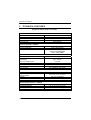
TECHNICAL FEATURES ......................................................................... 144
A
HOST CONFIGURATION STRINGS ........................................................ 149
B
CODE IDENTIFIER TABLE...................................................................... 162
C
HEX AND NUMERIC TABLE ................................................................... 165
v
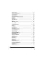
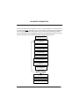
GENERAL VIEW
QUICKSCAN® MOBILE READERS
Reading Window
Trigger
Cradle
Locking System Latch
Charge completed
(yellow LED)
Charging
(red LED)
vi
INTRODUCTION
1
INTRODUCTION
The QuickScan® family provides a valuable solution for users seeking an affordable
handheld device without compromise in performance.
The extensive range of models and options of this family can easily meet any specific
challenges required by retail, and commercial data collections applications.
The QuickScan® Mobile is the ideal solution for retail and commercial environments
where continuous and multi-tasking activities are keys to optimum productivity, lower
cost of ownership and profitable business.
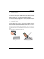
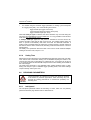
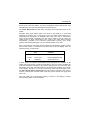
1.1
READING ANGLE
QuickScan® Mobile readers automatically scan barcodes at a distance. Simply aim
and pull the trigger. Code scanning is performed along the center of the light bar
emitted from the reading window. This bar must cover the entire code.
Successful scanning is obtained by tilting the reader with respect to the barcode to
avoid direct reflections, which could impair the reading performance. See the figures
below.
Successful reading is obtained by an audible tone.
Good read LED
OK
Not Advised
1
®
QUICKSCAN MOBILE
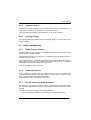
1.2
HANDS-FREE USE
When using the QuickScan® Mobile on the cradle, remember to lock the reader by
pushing up the locking system as indicated in the following figure.
2
INSTALLATION
2
INSTALLATION
2.1
USING YOUR QUICKSCAN® MOBILE READING SYSTEM
Follow the procedure below to start using your QuickScan® Mobile reading system:
1. Connect a QuickScan® Mobile cradle to the Host.
2. Insert the QuickScan® Mobile reader into the cradle to start the battery charging.
A full charge of the Lithium battery takes 3.5 – 6 hours.
To achieve the best battery life, it is recommended to perform a full
battery charge before using the reader in hand-held mode.
NOTE
In hands-free use, you can immediately start using the reader, since it is
powered by the cradle.
Configure the QuickScan® Mobile reader.
Configure the QuickScan® Mobile cradle.
3.
4.
2.2
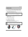
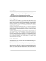
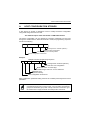
CHANGING THE BATTERIES
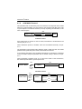
To change the battery of your reader, you must:
1. Unscrew the battery cover screw (Figure 1).
2. Unplug the white connector and remove the old battery (Figure 2).
3. Insert the new battery and plug in the white connector.
When inserting the new battery into the handle pay attention to
position the battery and the connector just as shown in Figure 3.
NOTE
Figure 1
Figure 2
Figure 3
3
®
QUICKSCAN MOBILE
4.
Insert the cover in the handle and screw it back into place.
Figure 4
WARNING
4
Do not incinerate, disassemble, short terminals or expose to
high temperature. Risk of fire, explosion. Use specified
charger only. Risk of explosion if the battery is replaced by
an incorrect type. Dispose of the batteries as required by the
relevant laws in force.
INSTALLATION
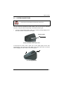
2.3
SYSTEM CONNECTIONS
Connections should always be made with power OFF!
CAUTION
You can connect the QuickScan® Mobile cradle to the Host through the dedicated
connector, using the cable corresponding to the desired interface type.
1.
Connect the appropriate interface cable to the cradle by simply plugging it into
the Host connector on the base of the cradle.
Interface Cable
QuickScan® Mobile Cradle - Bottom View
To disconnect the cable, insert a paper clip or other similar object into the hole
corresponding to the connector on the base of the cradle. Push down on the clip
while unplugging the cable. Refer to the following figure:
Disconnecting the Cable
5
®
QUICKSCAN MOBILE
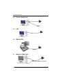
2.4
RS-232 CONNECTION
2.5
USB
2.6
IBM USB POS
CAB-413
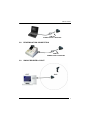
2.7
WEDGE CONNECTION
CAB-391 or CAB-321 + CAB-431
6
INSTALLATION
CAB-431
POWER SUPPLY ADAPTER
2.8
PEN EMULATION CONNECTION
CAB-431
POWER SUPPLY ADAPTER
2.9
SINGLE READER LAYOUT
7
®
QUICKSCAN MOBILE
3
CONFIGURATION
3.1
CONFIGURATION METHODS
3.1.1
Reading Configuration Barcodes
This manual can be used for complete setup and configuration of your reader by
following the setup procedures in this chapter (see par. Error! Reference source not
found. for an overview).
If you wish to change the default settings, this manual provides complete
configuration of your reader in an easy way.
To configure your reader:
1.
Open the folded page in Appendix C with the hex-numeric table and keep it open
during the device configuration.
2.
Read the Enter Configuration code ONCE, available at the top of each page of
configuration.
3.
Modify the desired parameters in one or more sections following the procedures
given for each group.
4.
Read the Exit and Save Configuration code ONCE, available at the top of each
page of configuration.
Reference notes describing the operation of the more complex parameters are given
in chapter 4.
3.1.2
Datalogic Aladdin™
Datalogic Aladdin™ is a multi-platform utility program that allows device configuration
using a PC. It provides RS-232 interface configuration as well as configuration
barcode printing.
3.1.3
Copy Command
A previously configured device (Master), can be used to send its configuration directly to
other devices of the same type (Slaves). The particular procedure for each device is
given in par. Error! Reference source not found..
8
CONFIGURATION
3.1.4
Sending Configuration Strings from Host
An alternative configuration method is provided in Appendix A using the RS-232 or
USB-COM interface. This method is particularly useful when many devices need to
be configured with the same settings. Batch files containing the desired parameter
settings can be prepared to configure devices quickly and easily.
3.2
QUICKSCAN® MOBILE STAND ALONE SETUP
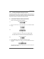
Read the restore default parameters code below.
®
1.
Restore QuickScan Mobile Default
2.
Read the codes below to set the radio address of the QuickScan® Mobile
reader.
Ì$+$*oÎ
Enter configuration
Ì$+;Î
3.
Set Radio Address
ÌRA0RFHÎ
+
four digits for the QuickScan® Mobile Address (from 0000 to 1999).
All readers used in the same area must have different addresses.
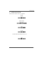
4.
Exit and Save configuration
5.
Read the Bind code to pair the QuickScan® Mobile to the cradle.
The reader is dedicated to the cradle. Any previously bound reader will be
excluded.
Ì$-?Î
Bind
Ì$+RN0$-IÎ
The yellow LED on the QuickScan® Mobile will blink; the reader is ready to be
positioned onto the cradle.
9
®
QUICKSCAN MOBILE
6.
Firmly position the reader onto the cradle within 10 seconds, a beep will be
emitted, signaling that the cradle has been paired to the QuickScan® Mobile,
and the yellow LED on the reader will go off.
Yellow LED
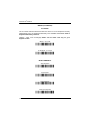
7.
Read the cradle restore default code:
Restore cradle default
Ì$+RX0$-qÎ
Go to par. 3.3 Interface Selection.
10
CONFIGURATION
3.3
INTERFACE SELECTION
Read the interface selection code for your application.
RS-232
Standard
Ì$+CP0$-$Î
POS Terminals
Nixdorf Mode A
Ì$+CM2EC0$->Î
Fujitsu
Ì$+CM1$-ÈÎ
ICL Mode
Ì$+CM0$-ÃÎ
For POS terminal default settings refer to par. 4.9.
PEN
Ì$+CP6$-BÎ
11
®
QUICKSCAN MOBILE
WEDGE
IBM AT or PS/2 PCs
Ì$+CP500$-aÎ
IBM XT
Ì$+CP503$-vÎ
PC Notebook
Ì$+CP505$-ÈÎ
IBM SURE1
Ì$+CP506$-$Î
IBM Terminal 3153
Ì$+CP504$-}Î
12
CONFIGURATION
WEDGE (CONTINUED)
IBM Terminals 31xx, 32xx, 34xx, 37xx:
To select the interface for these IBM Terminals, read the correct KEY
TRANSMISSION code. Select the KEYBOARD TYPE if necessary
(default = advanced keyboard).
KEY TRANSMISSION MODE
make-only keyboard
Ì$+CP502$-oÎ
make-break keyboard
Ì$+CP501$-hÎ
KEYBOARD TYPE
advanced keyboard
Ì$+FK1$-ÉÎ
typewriter keyboard
Ì$+FK0$-ÄÎ
13
®
QUICKSCAN MOBILE
WEDGE (CONTINUED)
ALT MODE
The ALT-mode selection allows barcodes sent to the PC to be interpreted correctly
independently from the Keyboard Nationality used. You do not need to make a
Keyboard Nationality selection.
(default = Num Lock Unchanged). Make sure the Num Lock key on your
keyboard is ON.
IBM AT - ALT mode
Ì$+CP507$-+Î
PC Notebook - ALT mode
Ì$+CP508$-2Î
WYSE TERMINALS
ANSI Keyboard
Ì$+CP509$-9Î
PC Keyboard
Ì$+CP510$-gÎ
ASCII Keyboard
Ì$+CP511$-nÎ
VT220 style Keyboard
Ì$+CP514$-ÇÎ
14
CONFIGURATION
WEDGE (CONTINUED)
DIGITAL TERMINALS
VT2xx/VT3xx/VT4xx
Ì$+CP512$-uÎ
IBM 46XX
(IBM Devices only)
PORT 9B
4501 Protocol
Ì$+CP800$-pÎ
(typical)
1520 Protocol
Ì$+CP801$-wÎ
PORT 5B
1520 Protocol
Ì$+CP801$-wÎ
(typical)
4501 Protocol
Ì$+CP800$-pÎ
15
®
QUICKSCAN MOBILE
3.4
USB READER CONFIGURATION
The USB interface is compatible with:
Windows 98 (and later)
Mac OS 8.0 (and later)
IBM POS for Windows
4690 Operating System
USB Start-up
As with all USB devices, upon connection, the Host performs several checks by
communicating with the QuickScan® Mobile. During this phase the yellow LED on the
QuickScan® Mobile reader blinks and normal operations are suspended. Two basic
conditions must be met before the QuickScan® Mobile is ready to read codes, the
correct USB driver must be loaded and sufficient power must be supplied to the
reader.
First Start-Up
For all systems, the correct USB driver for the default
USB-KBD interface is included in the Host Operating
System and will either be loaded automatically or will
be suggested by the O.S. and should therefore be
selected from the dialog box (the first time only).
Normally the Host supplies sufficient power to the
reader, the start-up phase ends correctly, the yellow
LED stops blinking.
In rare cases, if the Host does not supply sufficient
power to the reader, a dialog box will appear on the
Host and the reader will be blocked (yellow LED
continues blinking). In this case, disconnect the USB
device cable at the Host (yellow LED stops blinking);
and then try a different USB port as indicated by the
Operating System message. You can now read
codes.
Connect QuickScan
Mobile to Host
®
Yellow LED blinks
Load drivers
(if requested)
Yellow LED off –
BEEP OK
Select desired USB
interface code
(USB-KBD is default)
Load drivers
(if requested)
Read test codes.
Reader is READY
At this point you can read the USB interface
configuration code according to your application. Load drivers from the O.S. (if
requested). When configuring the USB-COM interface, the relevant files and drivers
must be installed from the USB Device Installation software, which can be
downloaded from the web page http://www.scanning.datalogic.com.
The reader is ready to read barcodes. Successive start-ups will automatically
recognize the previously loaded drivers.
16
CONFIGURATION
USB
USB-KBD
Ì$+UA03$-:Î
USB-KBD-ALT-MODE
Ì$+UA04$-@Î
USB-KBD-APPLE
Ì$+UA05$-FÎ
USB-COM*
Ì$+UA02$-4Î
USB-IBM-Table Top
Ì$+UA00$-(Î
USB-IBM-Hand Held
Ì$+UA01$-.Î
*
When configuring USB-COM, the relevant files and drivers must be installed from
the USB Device Installation software, which can be downloaded from the web site
http://www.scanning.datalogic.com.
17
QUICKSCAN® MOBILE
3.5
CHANGING DEFAULT SETTINGS
Once your reader is setup, you can change the default parameters to meet your
application needs. Refer to the preceding paragraphs for initial configuration in order
to set the default values and select the interface for your application.
In this manual, the configuration parameters are divided into logical groups making it
easy to find the desired function based on its reference group.
The first four groups are for Standard Interface parameter configuration:
RS-232
USB
WEDGE
PEN EMULATION
The following parameter groups are common to all interface applications:
DATA FORMAT parameters regard the messages sent to the Host system for all
interfaces except Pen Emulation.
READING PARAMETERS control various operating modes and indicator status
functioning.
DECODING PARAMETERS maintain correct barcode decoding in certain special
reading conditions.
CODE SELECTION parameters allow configuration of a personalized mix of codes,
code families and their options.
ADVANCED FORMATTING PARAMETERS allow code concatenation and advanced
formatting of messages towards the Host. It cannot be used with Pen Emulation
connections.
RADIO PARAMETERS (Mobile series only) allow configuration of radio control
parameters.
18
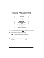
RS-232 PARAMETERS
BAUD RATE
PARITY
DATA BITS
STOP BITS
HANDSHAKING
ACK/NACK PROTOCOL
FIFO
INTER-CHARACTER DELAY
RX TIMEOUT
SERIAL TRIGGER LOCK
1.
Read the Enter Configuration code ONCE, available at the top of each page.
2.
Read configuration codes from the desired groups.
= Read the code and follow the procedure given
= Default value
3.
Read the Exit and Save Configuration code ONCE, available at the top of
each page.
19
Enter Configuration
Ì$+;Î
Exit and Save Configuration
RS-232
Ì$-?Î
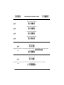
BAUD RATE
300 baud
ÌCD1XÎ
600 baud
ÌCD2[Î
1200 baud
ÌCD3^Î
2400 baud
ÌCD4aÎ
4800 baud
ÌCD5dÎ
9600 baud
ÌCD6gÎ
19200 baud
ÌCD7jÎ
38400 baud
ÌCD8mÎ
20
Enter Configuration
Ì$+;Î
Exit and Save Configuration
RS-232
Ì$-?Î
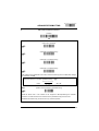
PARITY
none
ÌCC0SÎ
even parity
ÌCC1VÎ
odd parity
ÌCC2YÎ
DATA BITS
7 bits
ÌCA0OÎ
8 bits
ÌCA1RÎ
9 bits
ÌCA2UÎ
21
Enter Configuration
Ì$+;Î
Exit and Save Configuration
RS-232
STOP BITS
1 stop bit
ÌCB0QÎ
2 stop bits
ÌCB1TÎ
HANDSHAKING
disable
ÌCE0WÎ
hardware (RTS/CTS)
ÌCE1ZÎ
software (XON/XOFF)
ÌCE2]Î
RTS always ON
ÌCE3`Î
See par. 4.1.1 for details.
22
Ì$-?Î
Enter Configuration
Ì$+;Î
Exit and Save Configuration
RS-232
Ì$-?Î
ACK/NACK PROTOCOL
disable
ÌER0sÎ
enable
ÌER1vÎ
®
See par. 4.1.2 for details, particularly on implementing this parameter with QuickScan Mobile.
FIFO
disable
ÌEC0UÎ
enable
ÌEC1XÎ
See par. 4.1.3 for details.
23
Enter Configuration
Ì$+;Î
Exit and Save Configuration
RS-232
INTER-CHARACTER DELAY
delay between characters transmitted to Host
ÌCK3Î
Read 2 numbers from the table where:
00 = DELAY disabled
01-99 = DELAY from 1 to 99 milliseconds
delay disabled
RX TIMEOUT
timeout control in reception from Host
ÌCL5Î
Read 2 numbers from the table where:
00 = TIMEOUT disabled
01-99 = TIMEOUT from .1 to 9.9 seconds
rx timeout 5 seconds
See par. 4.1.4 for details.
24
Ì$-?Î
Enter Configuration
Ì$+;Î
Exit and Save Configuration
RS-232
Ì$-?Î
SERIAL TRIGGER LOCK
disabled
ÌCR0qÎ
enable and select characters
ÌCR1tÎ
Read 2 characters from the Hex/Numeric table in the range 00-FE where:
−
−
First Character enables device trigger
Second Character inhibits device trigger until the first character is received again.
25
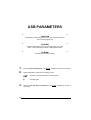
USB PARAMETERS
USB-COM
Handshaking, Ack/Nack protocol, FIFO, Inter-character delay, Rx
timeout, Serial trigger lock
USB-KBD
Keyboard nationality, FIFO, Inter-character delay, Inter-code
delay, Control character emulation, USB keyboard speed
USB-IBM
No parameter selection required.
1.
Read the Enter Configuration code ONCE, available at the top of each page.
2.
Read configuration codes from the desired groups.
= Read the code and follow the procedure given
= Default value
3.
26
Read the Exit and Save Configuration code ONCE, available at the top of
each page.
Enter Configuration
Ì$+;Î
Exit and Save Configuration
USB-COM
Ì$-?Î
HANDSHAKING
disable
ÌCE0WÎ
hardware (RTS/CTS)
ÌCE1ZÎ
software (XON/XOFF)
ÌCE2]Î
RTS always ON
ÌCE3`Î
See par. 4.1.1 for details.
ACK/NACK PROTOCOL
disable
ÌER0sÎ
enable
ÌER1vÎ
See par. 4.1.2 for details.
27
Enter Configuration
Ì$+;Î
Exit and Save Configuration
USB-COM
FIFO
disable
ÌEC0UÎ
enable
ÌEC1XÎ
See par. 4.1.3 for details.
INTER-CHARACTER DELAY
delay between characters transmitted to Host
ÌCK3Î
Read 2 numbers from the table where:
00 = DELAY disabled
01-99 = DELAY from 1 to 99 milliseconds
delay disabled
28
Ì$-?Î
Enter Configuration
Ì$+;Î
Exit and Save Configuration
USB-COM
Ì$-?Î
RX TIMEOUT
timeout control in reception from Host
ÌCL5Î
Read 2 numbers from the table where:
00 = TIMEOUT disabled
01-99 = TIMEOUT from .1 to 9.9 seconds
rx timeout 5 seconds
See par. 4.1.4 for details.
SERIAL TRIGGER LOCK
disabled
ÌCR0qÎ
enable and select characters
ÌCR1tÎ
Read 2 characters from the Hex/Numeric table in the range 00-FE where:
−
−
First Character enables device trigger
Second Character inhibits device trigger until the first character is received again.
29
Enter Configuration
Ì$+;Î
Exit and Save Configuration
USB-KBD
Ì$-?Î
KEYBOARD NATIONALITY
Not Available for USB-KBD-ALT-MODE Interface
This parameter default value is restored through the Interface Selection code and not Restore
Default.
Belgian
ÌFJ7yÎ
English
ÌFJ4pÎ
French
ÌFJ2jÎ
German
ÌFJ3mÎ
Italian
ÌFJ1gÎ
Japanese
ÌFJ8|Î
Spanish
ÌFJ6vÎ
Swedish
ÌFJ5sÎ
USA
ÌFJ0dÎ
30
Enter Configuration
Ì$+;Î
Exit and Save Configuration
USB-KBD
Ì$-?Î
FIFO
disable
ÌEC0UÎ
enable
ÌEC1XÎ
See par. 4.1.3 for details.
INTER-CHARACTER DELAY
delay between characters transmitted to Host
ÌCK3Î
Read 2 numbers from the table where:
00 = DELAY disabled
01-99 = DELAY from 1 to 99 milliseconds
delay disabled
31
Enter Configuration
Ì$+;Î
Exit and Save Configuration
USB-KBD
INTER-CODE DELAY
delay between codes transmitted to Host
ÌFG.Î
Read 2 numbers from the table where:
00 = DELAY disabled
01-99 = DELAY from 1 to 99 seconds
delay disabled
CONTROL CHARACTER EMULATION
CTRL + Shift + Key
ÌFO0nÎ
CTRL + Key
ÌFO1qÎ
32
Ì$-?Î
Enter Configuration
Ì$+;Î
Exit and Save Configuration
USB-KBD
Ì$-?Î
USB KEYBOARD SPEED
Normal
ÌUT10cÎ
Fast
ÌUT01dÎ
33
WEDGE PARAMETERS
KEYBOARD NATIONALITY
CAPS LOCK
CAPS LOCK
AUTO-RECOGNITION
NUM LOCK
INTER-CHARACTER DELAY
INTER-CODE DELAY
KEYBOARD SETTING
CONTROL CHARACTER
EMULATION
1.
Read the Enter Configuration code ONCE, available at the top of each page.
2.
Read configuration codes from the desired groups.
= Read the code and follow the procedure given
= Default value
3.
.
34
Read the Exit and Save Configuration code ONCE, available at the top of
each page.
Enter Configuration
Ì$+;Î
Exit and Save Configuration
WEDGE
Ì$-?Î
KEYBOARD NATIONALITY
Belgian
ÌFJ7yÎ
English
ÌFJ4pÎ
French
ÌFJ2jÎ
German
ÌFJ3mÎ
Italian
ÌFJ1gÎ
Spanish
ÌFJ6vÎ
Swedish
ÌFJ5sÎ
USA
ÌFJ0dÎ
The Japanese Keyboard Nationality selection is valid only for IBM AT compatible PCs.
Japanese
ÌFJ8|Î
35
Enter Configuration
Ì$+;Î
Exit and Save Configuration
WEDGE
Ì$-?Î
CAPS LOCK
caps lock OFF
ÌFE0ZÎ
caps lock ON
ÌFE1]Î
Select the appropriate code to match your keyboard caps lock status.
Note:
Caps lock manual configuration is ignored when Caps Lock Auto-Recognition is
enabled.
For PC Notebook interface selections, the caps lock status is automatically recognized;
therefore this command is not necessary.
CAPS LOCK AUTO-RECOGNITION (IBM AT COMPATIBLE ONLY)
disable
ÌFP0pÎ
enable
ÌFP1sÎ
36
Enter Configuration
Ì$+;Î
Exit and Save Configuration
WEDGE
Ì$-?Î
NUM LOCK
toggle num lock
ÌFL1kÎ
num lock unchanged
ÌFL0hÎ
This selection is used together with the Alt Mode interface selection for AT or Notebook PCs.
It changes the way the Alt Mode procedure is executed; therefore it should be set as follows:
•
if your keyboard Num Lock is normally on use num lock unchanged
•
if your keyboard Num Lock is normally off use toggle num lock
In this way the device will execute the Alt Mode procedure correctly for your application.
INTER-CHARACTER DELAY
delay between characters transmitted to Host
ÌCK3Î
Read 2 numbers from the table where:
00 = DELAY disabled
01-99 = DELAY from 1 to 99 milliseconds
delay disabled
37
Enter Configuration
Ì$+;Î
Exit and Save Configuration
WEDGE
INTER-CODE DELAY
delay between codes transmitted to Host
ÌFG.Î
Read 2 numbers from the table where:
00 = DELAY disabled
01-99 = DELAY from 1 to 99 seconds
delay disabled
38
Ì$-?Î
Enter Configuration
Exit and Save Configuration
Ì$+;Î
WEDGE
Ì$-?Î
KEYBOARD SETTING
ALPHANUMERIC KEYBOARD SETTING
The reader can be used with terminals or PCs with various keyboard types and nationalities
through a simple keyboard setting procedure.
The type of computer or terminal must be selected before activating the keyboard setting
command.
Keyboard setting consists of communicating to the reader how to send data corresponding to
the keyboard used in the application. The keys must be set in a specific order.
Press and release a key to set it.
Some characters may require more than one key pressed simultaneously during normal use
(refer to the manual of your PC or terminal for keyboard use). The exact sequence must be
indicated to the reader in this case pressing and releasing the different keys.
Example:
If one has to press the "Shift" and "4" keys simultaneously on the keyboard to transmit the
character "$" to the video, to set the "$", press and release "Shift" then press and release "4".
Each pressed and released key must generate an acoustic signal on the reader, otherwise
repress the key. Never press more than one key at the same time, even if this corresponds to
the normal use of your keyboard.
Press "Backspace" to correct a wrong key entry. In this case the reader emits 2 beeps.
Note: "CAPS LOCK" and "NUM LOCK" must be off before starting the keyboard setting
procedure. "SHIFT" must be repressed for each character and cannot be substituted by
"CAPS LOCK".
setting the alphanumeric keyboard
ÌFB0TÎ
Read the code above.
Press the keys shown in the following table according to their numerical order.
Some ASCII characters may be missing as this depends on the type of keyboard: these are
generally particular characters relative to the various national symbologies. In this case:
•
The first 4 characters (Shift, Alt, Ctrl, and Backspace) can only be substituted with
keys not used, or substituted with each other.
•
characters can be substituted with other single symbols (e.g. "SPACE") even if not
included in the barcode set used.
•
characters can be substituted with others corresponding to your keyboard.
The reader signals the end of the procedure with 2 beeps indicating the keys have
been registered.
39
Enter Configuration
Exit and Save Configuration
Ì$+;Î
01 : Shift
02 : Alt
03 : Ctrl
04 : Backspace
05 : SPACE
06 : !
07 : "
08 : #
09 : $
10 : %
11 : &
12 : '
13 : (
14 : )
15 : *
16 : +
17 : ,
18 : 19 : .
20 : /
21 : 0
22 : 1
23 : 2
24 : 3
25 : 4
26 : 5
27 : 6
Ì$-?Î
WEDGE
28 : 7
29 : 8
30 : 9
31 : :
32 : ;
33 : <
34 : =
35 : >
36 : ?
37 : @
38 : A
39 : B
40 : C
41 : D
42 : E
43 : F
44 : G
45 : H
46 : I
47 : J
48 : K
49 : L
50 : M
51 : N
52 : O
53 : P
54 : Q
55 : R
56 : S
57 : T
58 : U
59 : V
60 : W
61 : X
62 : Y
63 : Z
64 : [
65 : \
66 : ]
67 : ^
68 : _ (underscore)
69 : `
70 : {
71 : |
72 : }
73 : ~
74 : DEL
The keyboard setup functioning is signaled by the LEDs on the cradle. Each key stroke
corresponds to a double blinking of the yellow LED.
By pressing the Backspace key the red LED on the cradle blinks, while the yellow LED stays on.
Do not place the reader onto the cradle during this procedure. Otherwise,
the battery charging will occur modifying the LEDs functioning.
CAUTION
Once the procedure has been completed, the yellow LED turns off.
40
Enter Configuration
Ì$+;Î
Exit and Save Configuration
WEDGE
Ì$-?Î
CONTROL CHARACTER EMULATION
CTRL + Shift + Key
ÌFO0nÎ
CTRL + Key
ÌFO1qÎ
41
PEN EMULATION
OPERATING MODE
MINIMUM OUTPUT PULSE
CONVERSION TO CODE 39
OVERFLOW
OUTPUT LEVEL
IDLE LEVEL
INTER-BLOCK DELAY
1.
Read the Enter Configuration code ONCE, available at the top of each page.
2.
Read configuration codes from the desired groups.
= Default value
3.
42
Read the Exit and Save Configuration code ONCE, available at the top of
each page.
PEN EMULATION
The operating mode parameters are complete commands and do not require reading the
Enter and Exit configuration codes.
OPERATING MODE
interpret mode
Ì$]8Î
Interprets commands without sending them to the decoder.
transparent mode
Ì$[4Î
Sends commands to the decoder without interpreting them.
43
Enter Configuration
Ì$+;Î
Exit and Save Configuration
PEN EMULATION
Ì$-?Î
MINIMUM OUTPUT PULSE
high resolution code
emulation
200 µs
ÌDG0\Î
400 µs
ÌDG1_Î
600 µs
ÌDG2bÎ
800 µs
ÌDG3eÎ
1 ms
ÌDG4hÎ
1.2 ms
low resolution code
emulation
See par. 4.2.1 for details.
44
ÌDG5kÎ
Enter Configuration
Ì$+;Î
Exit and Save Configuration
PEN EMULATION
Ì$-?Î
CONVERSION TO CODE 39 AND CODE 128
disable conversion to Code 39
ÌDA0PÎ
Transmits codes in their original format.
enable conversion to Code 39
ÌDA1SÎ
Converts codes read into Code 39 format.
enable conversion to Code 128
ÌDA2VÎ
Converts codes read into Code 128 format.
See par. 4.2.2 for details.
45
Enter Configuration
Ì$+;Î
Exit and Save Configuration
PEN EMULATION
OVERFLOW
narrow
ÌDH0^Î
medium
ÌDH1aÎ
wide
ÌDH2dÎ
See par. 4.2.3 for details.
OUTPUT LEVEL
normal
(white = logic level 0)
ÌDD0VÎ
inverted
(white = logic level 1)
ÌDD1YÎ
See par. 4.2.4 for details.
46
Ì$-?Î
Enter Configuration
Ì$+;Î
Exit and Save Configuration
PEN EMULATION
Ì$-?Î
IDLE LEVEL
normal
(black level)
ÌDE0XÎ
inverted
(white level)
ÌDE1[Î
See par. 4.2.4 for details.
INTER-BLOCK DELAY
delay between character blocks transmitted to Host
ÌCK3Î
Read 2 numbers from the table where:
00 = DELAY disabled
01-99 = DELAY from .1 to 9.9 seconds
delay disabled
See par. 4.2.5 for details.
47
IBM 46XX
IBM DATA FORMATTING
1.
Read the Enter Configuration code ONCE, available at the top of each page.
2.
Read configuration codes from the desired groups.
= Default value
3.
48
Read the Exit and Save Configuration code ONCE, available at the top of
each page.
Enter Configuration
Ì$+;Î
Exit and Save Configuration
IBM 46xx
Ì$-?Î
IBM DATA FORMATTING
conversion to Code 39
ÌGD0YÎ
IBM Standard
ÌGD1\Î
mixed IBM Standard + Code 39
ÌGD2_Î
See par. 4.3.1 for details.
49
DATA FORMAT
NOT FOR PEN INTERFACES
CODE IDENTIFIER
CUSTOM CODE IDENTIFIER
HEADER
TERMINATOR
SPECIAL KEYS
FIELD ADJUSTMENT
FIELD ADJ. CHARACTER
CODE LENGTH TX
CHARACTER REPLACEMENT
ADDRESS STAMPING
ADDRESS DELIMITER
1.
Read the Enter Configuration code ONCE, available at the top of each page.
2.
Read configuration codes from the desired groups.
= Read the code and follow the procedure given
= Default value
3.
50
Read the Exit and Save Configuration code ONCE, available at the top of
each page.
DATA FORMAT
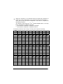
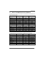
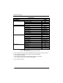
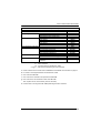
CODE IDENTIFIER TABLE
CODE
2/5 interleaved
2/5 industrial
2/5 normal 5 bars
2/5 matrix 3 bars
EAN 8
EAN 13
UPC A
UPC E
EAN 8 with 2 ADD ON
EAN 8 with 5 ADD ON
EAN 13 with 2 ADD ON
EAN 13 with 5 ADD ON
UPC A with 2 ADD ON
UPC A with 5 ADD ON
UPC E with 2 ADD ON
UPC E with 5 ADD ON
Code 39
Code 39 Full ASCII
CODABAR
ABC CODABAR
Code 128
EAN 128
ISBT 128
Code 93
CIP/39
CIP/HR
Code 32
MSI
Plessey Standard
Plessey Anker
Telepen
Delta IBM
Code 11
Code 16K
Code 49
RSS Expanded Linear and Stacked
RSS Limited
RSS 14 Linear and Stacked
AIM STANDARD
DATALOGIC STANDARD
]Iy
]Xy
]Sy
]Xy
]E4
]E0
]Xy
]Xy
]E5
]E6
]E1
]E2
]Xy
]Xy
]Xy
]Xy
]Ay
]Ay
]Fy
]Xy
]Cy
]Cy
] C4
]Gy
]Xy
]Xy
]Xy
]My
]P0
]P1
]X0
]X0
]Hy
]K0
]Ty
]e0
]e0
]e0
N
P
O
Q
A
B
C
D
J
K
L
M
F
G
H
I
V
W
R
S
T
k
f
U
Y
e
X
Z
a
o
d
c
b
p
q
t
v
u
Custom
51
DATA FORMAT
•
AIM standard identifiers are not defined for all codes: the X identifier is assigned to the
code for which the standard is not defined. The y value depends on the selected options
(check digit tested or not, check digit tx or not, etc.).
•
When customizing the Datalogic Standard code identifiers, 1 or 2 identifier characters can
be defined for each code type. If only 1 identifier character is required, the second
character must be selected as FF (disabled).
•
The code identifier can be singly disabled for any code by simply selecting FF as the first
identifier character.
•
Write in the Custom character identifiers in the table above for your records.
52
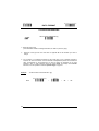
Enter Configuration
Ì$+;Î
Exit and Save Configuration
DATA FORMAT
Ì$-?Î
CODE IDENTIFIER
disable
ÌEB0SÎ
Datalogic standard
ÌEB1VÎ
AIM standard
ÌEB2YÎ
custom
ÌEB3\Î
53
Enter Configuration
Exit and Save Configuration
Ì$+;Î
Ì$-?Î
DATA FORMAT
CUSTOM CODE IDENTIFIER
define custom code identifier(s)
ÌEH/Î
Read the above code.
(Code Identifiers default to Datalogic standard, see table on previous page).
Select the code type from the code table in Appendix B for the identifier you want to
change.
You can define 1 or 2 identifier characters for each code type. If only 1 identifier character is
required, the second character must be selected as FF (disabled). Read the hexadecimal
value corresponding to the character(s) you want to define as identifiers for the code
selected in step : valid characters are in the range 00-FD. For Wedge and USB-KBD
interfaces, it is also possible to read the Special Key(s) on page 57.
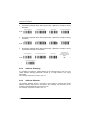
Example:
To define Code 39 Code Identifier = @
define custom code identifier(s)
Read
54
ÌEH/Î
Code 39
+
ÌVWÎ
+
40
+
FF
Enter Configuration
Ì$+;Î
Exit and Save Configuration
Ì$-?Î
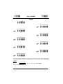
DATA FORMAT
HEADER
no header
ÌEA00*Î
one character header
ÌEA01.Î
two character header
ÌEA022Î
three character header
ÌEA036Î
four character header
ÌEA04:Î
five character header
ÌEA05>Î
six character header
ÌEA06BÎ
seven character header
ÌEA07FÎ
eight character header
ÌEA08JÎ
After selecting one of the desired Header codes, read the character(s) from the HEX table. Valid characters
are in the range 00-FE. For Wedge and USB-KBD interfaces, it is also possible to read the Special Key(s)
on page 57.
Example:
four character header
+ 41 + 42 + 43 + 44 = Header ABCD
For more details see par. 4.4.1.
55
Enter Configuration
Ì$+;Î
Exit and Save Configuration
Ì$-?Î
DATA FORMAT
TERMINATOR
no terminator
ÌEA10-Î
one character terminator
ÌEA111Î
two character terminator
ÌEA125Î
three character terminator
ÌEA139Î
four character terminator
ÌEA14=Î
five character terminator
ÌEA15AÎ
six character terminator
ÌEA16EÎ
seven character terminator
ÌEA17IÎ
eight character terminator
ÌEA18MÎ
After selecting one of the desired Header codes, read the character(s) from the HEX table. Valid characters
are in the range 00-FE. For Wedge and USB-KBD interfaces, it is also possible to read the Special Key(s)
on page 57.
Example:
two character terminator
+ 0D + 0A = Terminator CR LF
For more details see par. 4.4.1.
56
Enter Configuration
Ì$+;Î
Exit and Save Configuration
DATA FORMAT
Ì$-?Î
SPECIAL KEYS
Available only for Wedge IBM AT-PS/2 and USB-KBD Interfaces
It is necessary to define each Special Key by following the procedure given in
par. 4.4.2.
NOTE
Select one or more of the following Special Keys according to your needs.
Special Key 1
Ì9CÄÎ
Special Key 2
Ì9DÆÎ
Special Key 3
Ì9EÈÎ
Special Key 4
Ì9FÊÎ
Special Key 5
ÌA0bÎ
57
Enter Configuration
Ì$+;Î
Exit and Save Configuration
Ì$-?Î
DATA FORMAT
FIELD ADJUSTMENT
disable field adjustment
ÌEF0[Î
Field adjustment allows a number of characters n, to be added to or subtracted from the
barcode read. The adjustment can be different for each enabled code type. To define the field
adjustment:
Read the enable field adjustment code:
enable field adjustment
ÌEF+Î
Select the code type from the Code Identifier Table in Appendix B.
Select the type of adjustment to perform:
right addition
Ì01Î
left addition
Ì12Î
right deletion
Ì23Î
left deletion
Ì34Î
Read a number in the range 01 - 32 from the Hex/Numeric Table to define how many
characters to add or delete:
Conditions:
•
Adjustment is only performed on the barcode data; the Code Identifier and Code Length
Transmission fields are not modified by the field adjustment parameter.
•
If the field setting would subtract more characters than exist in the barcode, the subtraction
will take place only to code length 0.
•
You can set up to a maximum of 10 different field adjustments on the same barcode family
or on different barcode families.
Example: To add 4 characters to the right of Standard Code 39 Codes:
enable field adjustment
Read
58
ÌEF+Î
Code 39
+
ÌVWÎ
right addition
+
Ì01Î
+
04
Enter Configuration
Ì$+;Î
Exit and Save Configuration
DATA FORMAT
Ì$-?Î
FIELD ADJUSTMENT CHARACTER
Read the field adjustment character code:
field adjustment character
ÌEG-Î
Read the hexadecimal value corresponding to the character you want to use for field
adjustment. Valid characters are in the range 00-FE. For Wedge and USB-KBD interfaces, it
is also possible to read the Special Key(s) on page 57.
Example:
To define the field adjustment character = A:
field adjustment character
Read
+ 41
CODE LENGTH TX
code length not transmitted
ÌEE0YÎ
code length transmitted in variable-digit format
ÌEE1\Î
code length transmitted in fixed 4-digit format
ÌEE2_Î
The code length is transmitted in the message after the Headers and Code Identifier characters.
The code length is calculated after performing any field adjustment operations.
59
Enter Configuration
Ì$+;Î
Exit and Save Configuration
DATA FORMAT
Ì$-?Î
CHARACTER REPLACEMENT
disable character replacement
ÌEO0mÎ
This parameter allows up to three characters to be replaced from the barcode read. These
substitutions are stored in memory. To define each character replacement:
Read one of the following character replacement codes:
first character replacement
ÌEO1pÎ
second character replacement
ÌEO2sÎ
third character replacement
ÌEO3vÎ
From the Code Identifier Table in Appendix B, read the Code Identifier for the desired
code family.
0 = character replacement will be effective for all code families.
From the Hex/Numeric Table read two characters corresponding to the Hex value (00-FE)
which identifies the character to be replaced. For Wedge and USB-KBD interfaces, it is
also possible to read the Special Key(s) on page 57.
From the Hex/Numeric Table read two characters corresponding to the Hex value (00-FE)
which identifies the new character to replace. For Wedge and USB-KBD interfaces, it is
also possible to read the Special Key(s) on page 57.
FF = the character to be replaced will be substituted with no character, that is, it will be
removed from the code.
60
Enter Configuration
Exit and Save Configuration
Ì$+;Î
Ì$-?Î
DATA FORMAT
Example:
The following strings define:
1.
First Character Replacement: substitution in Code 39 barcodes of all occurrences of the
0 character with the 1 character.
2.
Second Character Replacement: substitution in Code 39 barcodes of all occurrences of
the A character with the B character.
first character replacement
Code 39
ÌEO1pÎ + ÌVWÎ +
ASCII characters corresponding
to the HEX value for character 0
30
ASCII characters corresponding
to the HEX value for character 1
+
31
For Code 39 codes containing the string "0123", the contents transmitted will be "1123".
second character
replacement
Code 39
ÌEO2sÎ + ÌVWÎ +
ASCII characters corresponding
to the HEX value for character A
41
ASCII characters corresponding
to the HEX value for character B
+
42
For Code 39 codes containing the string "ABCD", the contents transmitted will be "BBCD".
61
ADDRESS STAMPING
disable reader address stamping
ÌRU0ÊÎ
enable reader address stamping
ÌRU1"Î
See par. 4.4.3 for details.
ADDRESS DELIMITER
disable reader address delimiter
ÌRV0!Î
enable reader address delimiter and select characters
ÌRV1$Î
Read 2 HEX characters in the range 00-FE.
See par. 4.4.4 for details.
62
READING PARAMETERS
HAND-HELD OPERATION
STAND OPERATION
HARDWARE TRIGGER MODE
TRIGGER-OFF TIMEOUT
FLASH MODE
READS PER CYCLE
SAFETY TIME
BEEPER INTENSITY
BEEPER TONE
BEEPER TYPE
BEEPER LENGTH
STAND RECOGNITION BEEP
1.
Read the Enter Configuration code ONCE, available at the top of each page.
2.
Read configuration codes from the desired groups.
= Read the code and follow the procedure given
= Default value
3.
Read the Exit and Save Configuration code ONCE, available at the top of
each page.
63
Enter Configuration
Exit and Save Configuration
Ì$+;Î
READING PARAMETERS
Ì$-?Î
HAND-HELD OPERATION
hardware trigger
ÌBK1eÎ
software trigger
ÌBK0bÎ
* always on
ÌBK3kÎ
* not available for Mobile series readers
automatic
ÌBK2hÎ
hardware trigger ready
ÌBK4nÎ
STAND OPERATION
ONLY Devices with Stand Recognition Beep
hardware trigger
ÌBU3ÃÎ
software trigger
ÌBU1yÎ
* always on
ÌBU2|Î
* not available for Mobile series readers
automatic
ÌBU0vÎ
64
Enter Configuration
Ì$+;Î
Exit and Save Configuration
READING PARAMETERS
Ì$-?Î
HARDWARE TRIGGER MODE
trigger active level
ÌBA0NÎ
trigger active pulse
ÌBA1QÎ
See par. 4.5.1 for details
TRIGGER-OFF TIMEOUT
trigger-off timeout
ÌBD$Î
Read 2 numbers in the range 00-99:
00 = disables the trigger-off timeout
01-99 = corresponds to a max. 99-sec. delay after the trigger
press to allow the reader to turn off automatically.
trigger-off timeout disabled
See par. 4.5.2 for details.
65
Enter Configuration
Ì$+;Î
Exit and Save Configuration
READING PARAMETERS
FLASH MODE
"FLASH" ON duration
ÌBB0PÎ
"FLASH" OFF duration
ÌBB1SÎ
Read 2 numbers in the range 01-99:
01 to 99 = from .1 to 9.9 seconds.
Flash-ON = 1 sec. Flash-OFF = 0.6 sec
READS PER CYCLE
one read per cycle
ÌBC0RÎ
multiple reads per cycle
ÌBC1UÎ
See par. 4.5.3 for details.
66
Ì$-?Î
Enter Configuration
Ì$+;Î
Exit and Save Configuration
READING PARAMETERS
Ì$-?Î
SAFETY TIME
safety time
ÌBE&Î
Limits same code consecutive reading.
Read 2 numbers in the range 00-99:
00 = no same code consecutive reading until reader is
removed (no decoding) for at least 400 ms.
01-99 = timeout from .1 to 9.9 seconds before a consecutive read
on same code.
safety time = 0.5 sec
See par. 4.5.4 for details.
BEEPER INTENSITY
* very low intensity
ÌBG0ZÎ
low intensity
ÌBG1]Î
medium intensity
ÌBG2`Î
high intensity
ÌBG3cÎ
*
This sets the beeper OFF for data entry, while for all other beeper signals it has the
meaning “very low intensity”. The Beeper Intensity parameter is effective for all operating
conditions described in par. 5.2.
67
Enter Configuration
Ì$+;Î
Exit and Save Configuration
READING PARAMETERS
Ì$-?Î
BEEPER TONE
tone 1
ÌBH0\Î
tone 2
ÌBH1_Î
tone 3
ÌBH2bÎ
tone 4
ÌBH3eÎ
BEEPER TYPE
monotone
ÌBJ0`Î
bitonal
ÌBJ1cÎ
BEEPER LENGTH
long
ÌBI0^Î
short
ÌBI1aÎ
68
Enter Configuration
Ì$+;Î
Exit and Save Configuration
READING PARAMETERS
Ì$-?Î
STAND RECOGNITION BEEP
ONLY Devices with Stand Recognition
disable
ÌBV0xÎ
enable
ÌBV1{Î
69
DECODING PARAMETERS
INK SPREAD
OVERFLOW CONTROL
INTERDIGIT CONTROL
DECODING SAFETY
PUZZLE SOLVER™
Before changing these parameter values read the descriptions in
par. 4.6.
CAUTION
1.
2.
3.
70
Read the Enter Configuration code ONCE, available at the top of each page.
Read configuration codes from the desired groups.
= Default value
Read the Exit and Save Configuration code ONCE, available at the top of
each page.
Enter Configuration
Ì$+;Î
Exit and Save Configuration
DECODING PARAMETERS
Ì$-?Î
INK SPREAD
disable
ÌAX0{Î
enable
ÌAX1~Î
See par. 4.6.1 for details.
OVERFLOW CONTROL
disable
ÌAW1|Î
enable
ÌAW0yÎ
See par. 4.6.2 for details.
71
Enter Configuration
Exit and Save Configuration
Ì$+;Î
Ì$-?Î
DECODING PARAMETERS
INTERDIGIT CONTROL
disable
ÌAV0wÎ
enable
ÌAV1zÎ
See par. 4.6.3 for details.
DECODING SAFETY
one read
ÌED0WÎ
(decoding safety disabled)
two reads
ÌED1ZÎ
three reads
ÌED2]Î
four reads
ÌED3`Î
Required number of good reads before accepting code.
72
Enter Configuration
Exit and Save Configuration
Ì$+;Î
DECODING PARAMETERS
Ì$-?Î
PUZZLE SOLVER™
disable
ÌAU0uÎ
enable
ÌAU1xÎ
In the case of damaged or poorly printed codes, this parameter allows reading multiple parts of
the single code to reconstruct it.
To read codes using this technology, simply move the illuminated bar over the code so that
each line of the code is scanned. During this process a series of brief “ticks” indicates that
reading is proceeding correctly.
Conditions:
•
This parameter is only valid for the following codes:
EAN 8
without Add-on
EAN 13
without Add-on
Code 128
Code 39
•
For Code 39, Check digit control is forced.
•
PuzzleSolver™ is not valid for ISBT 128 code.
UPC A
without Add-on
73
CODE SELECTION
EAN/UPC FAMILY
2/5 FAMILY
CODE 39 FAMILY
CODE 128 FAMILY
CODABAR FAMILY
CODE 93
MSI
PLESSEY
TELEPEN
DELTA IBM
CODE 11
CODE 16K
CODE 49
GS1 DATABAR™
1.
Read the Enter Configuration code ONCE, available at the top of each page.
2.
Read configuration codes from the desired groups.
= Read the code and follow the procedure given
= Default value
3.
74
Read the Exit and Save Configuration code ONCE, available at the top of
each page.
Enter Configuration
Exit and Save Configuration
Ì$+;Î
CODE SELECTION
Ì$-?Î
DISABLE ALL CODE FAMILIES
ÌAZ0ÃÎ
The reader allows up to 5 code selections. This does not limit the
number of CODES enabled to 5, as it depends on the code family.
NOTE
SINGLE
SELECTIONS =
•
ONE combination code from the EAN family
•
ONE code from the 2/5 family
Example
5 code selections:
1. 2/5 Interleaved
2. 2/5 Industrial
3. Code 128 + EAN 128
4. Code 39 Full ASCII + Code 32
5. UPC A/UPC E
In this section all SINGLE code selections are underlined and in bold.
75
Enter Configuration
Ì$+;Î
Exit and Save Configuration
CODE SELECTION
Ì$-?Î
EAN/UPC FAMILY
disable the family
ÌAA0MÎ
Read the desired family code
Note:
Since the EAN/UPC without ADD ON code selection is enabled by default, to correctly enable
another selection, first disable the family.
WITHOUT ADD ON
EAN 8/EAN 13/UPC A/UPC E
ÌAA1PÎ
EAN 8/EAN 13
ÌAA3VÎ
UPC A/UPC E
ÌAA4YÎ
76
Enter Configuration
Exit and Save Configuration
Ì$+;Î
Ì$-?Î
CODE SELECTION
WITH ADD ON 2 AND 5
EAN 8/EAN 13/UPC A/UPC E
ÌAA5\Î
EAN 8/EAN 13
ÌAA6_Î
UPC A/UPC E
ÌAA7bÎ
WITH ADD ON 2 ONLY
EAN 8/EAN 13
ÌAAK7Î
UPC A/UPC E
ÌAAM=Î
WITH ADD ON 5 ONLY
EAN 8/EAN 13
ÌAAL:Î
UPC A/UPC E
ÌAAN@Î
77
Enter Configuration
Ì$+;Î
Exit and Save Configuration
CODE SELECTION
Ì$-?Î
WITH AND WITHOUT ADD ON
EAN/UPC with and without ADD ON no
Autodiscrimination
ÌAA8Ad03Î
EAN/UPC Autodiscrimination ADD ON by
Prefix
ÌAA8Ad19Î
By setting the EAN/UPC Autodiscrimination ADD ON by Prefix, the desired prefixes
must be selected by reading the corresponding codes given in the following section,
since no prefix is configured by default.
78
Enter Configuration
Exit and Save Configuration
Ì$+;Î
Ì$-?Î
CODE SELECTION
SELECT EAN/UPC PREFIXES
NOTE
When scanning the following codes, barcodes starting with the
selected prefixes will be read and transmitted only if the ADD ON is
present. If no ADD ON is found, the barcode will not be read.
Barcodes starting with different characters are read regardless of ADD
ON presence and transmitted always without ADD ON.
Cancel All Selections
ÌET0wÎ
OR
select one or more of the following prefixes:
378/379
ÌET1378ET2379PÎ
434/439
ÌET3434ET4439ÉÎ
414/419
ÌET5414ET6419}Î
977
ÌET7977QÎ
978
ÌET8978ZÎ
979
ÌET9979cÎ
The commands above are not mutually exclusive. They can be used to configure
more than one set of prefixes simultaneously.
79
Enter Configuration
Exit and Save Configuration
Ì$+;Î
CODE SELECTION
Ì$-?Î
Example:
The following string allows reading and transmitting with ADD ON all EAN/UPC starting with the
434/439, 977 and 978 prefixes:
1.
EAN/UPC Autodiscrimination ADD ON by Prefix.
2.
434/439: enables reading and transmission with ADD ON of all EAN/UPC barcodes
starting with 434/439 prefixes.
3.
977: enables reading and transmission with ADD ON of all EAN/UPC barcodes starting
with 977 prefix.
4.
978: enables reading and transmission with ADD ON of all EAN/UPC barcodes starting
with 978 prefix.
EAN/UPC Autodiscrimination ADD ON by
Prefix
ÌAA8Ad19Î
434/439
+
ÌET3434ET4439ÉÎ
977
+
ÌET7977QÎ
To clear the current prefix selections:
1.
Cancel all Selections
Cancel All Selections
ÌET0wÎ
80
978
+
ÌET8978ZÎ
+
Enter Configuration
Exit and Save Configuration
Ì$+;Î
Ì$-?Î
CODE SELECTION
EAN/UPC CHECK DIGIT TX SELECTIONS
For each code type in this family you can choose to transmit the check digit or not
CHECK DIGIT TRANSMISSION
NO CHECK DIGIT
TRANSMISSION
EAN 8
ÌAAG1oÎ
EAN 8
ÌAAG0kÎ
EAN 13
ÌAAH1rÎ
EAN 13
ÌAAH0nÎ
UPC A
ÌAAI1uÎ
UPC A
ÌAAI0qÎ
UPC E
ÌAAJ1xÎ
UPC E
ÌAAJ0tÎ
81
Enter Configuration
Ì$+;Î
Exit and Save Configuration
CODE SELECTION
CONVERSION OPTIONS
UPC E to UPC A conversion
ÌAAAÄÎ
UPC E to EAN 13 conversion
ÌAABÇÎ
UPC A to EAN 13 conversion
ÌAACÊÎ
EAN 8 to EAN 13 conversion
ÌAAD"Î
Enable only ISBN conversion
ÌAP1nÎ
Enable only ISSN conversion
ÌAP2qÎ
Enable both ISBN and ISSN conversion
ÌAP3tÎ
Disable both ISBN and ISSN conversion
ÌAP0kÎ
82
Ì$-?Î
Enter Configuration
Ì$+;Î
Exit and Save Configuration
CODE SELECTION
Ì$-?Î
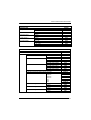
2/5 FAMILY
disable the family
ÌAC0QÎ
Read the desired family code
Read a check digit selection
Interleaved 2/5
ÌAC1TÎ
CHECK DIGIT TABLE
no check digit control
Ì12Î
Normal 2/5 (5 Bars)
ÌAC2WÎ
check digit control and transmission
Ì23Î
Industrial 2/5 (IATA)
ÌAC3ZÎ
check digit control without transmission
Ì34Î
Matrix 2/5 (3 Bars)
ÌAC4]Î
−
−
The pharmaceutical code below is part of
the 2/5 family but has no check digit or
code length selections.
Code CIP/HR
ÌAC5`Î
French pharmaceutical code
Read 4 numbers for the code length
where:
First 2 digits = minimum code
length.
Second 2 digits = maximum code
length.
The maximum code length is 99
characters.
The minimum code length must always
be less than or equal to the maximum.
Examples:
0199 = variable from 1 to 99 digits in
the code.
1010 = 10 digit code length only.
83
Enter Configuration
Ì$+;Î
Exit and Save Configuration
CODE SELECTION
Ì$-?Î
CODE 39 FAMILY
disables the family
ÌAB0OÎ
Read the desired family code
Read a check digit selection
CHECK DIGIT TABLE
Standard Code 39
no check digit control
ÌAB1RÎ
Ì12Î
Full ASCII Code 39
ÌAB2UÎ
check digit control
and transmission
Ì23Î
check digit control
without transmission
Ì34Î
84
Enter Configuration
Ì$+;Î
Exit and Save Configuration
CODE SELECTION
Ì$-?Î
The pharmaceutical codes below are part of the Code 39 family but have no check digit
selections.
Code CIP39
ÌAB3XÎ
French pharmaceutical code
Code 32
ÌAB4[Î
Italian pharmaceutical code
CODE LENGTH (optional)
The code length selection is valid for the entire Code 39 family
Read the code + 4 numbers for the code length where:
First 2 digits = minimum code length.
Second 2 digits = maximum code length.
set code length
ÌAB*=Î
The maximum code length is 99 characters.
The minimum code length must always be less than or equal to the maximum.
Examples: 0199 = variable from 1 to 99 digits in the code. 1010 = 10 digit code length only.
85
Enter Configuration
Ì$+;Î
Exit and Save Configuration
CODE SELECTION
Ì$-?Î
CODE 128 FAMILY
disables the family
ÌAI0]Î
Read the desired family code
Code 128
ÌAI11=Î
control without transmission
of check digit
EAN 128
ÌAI21@Î
control without transmission
of check digit
Transmit GS Before Code
Code EAN 128 uses the ASCII <GS> character to separate a variable length code field from the
next code field. This character can also be transmitted before the code.
disable
ÌEQ0qÎ
enable
ÌEQ1tÎ
If the <GS> character has been modified in the Character Replacement parameter, the new
character is affected by this command.
86
Enter Configuration
Ì$+;Î
Exit and Save Configuration
CODE SELECTION
Ì$-?Î
ISBT 128
ÌAI31CÎ
Enabling ISBT 128 automatically disables Puzzle Solver™.
CODE LENGTH (optional)
The code length selection is valid for the entire Code 128 family.
Read the code + 4 numbers for the code length where:
set code length
ÌAILJÎ
First 2 digits = minimum code length
Second 2 digits = maximum code length
The maximum code length is 99 characters. The minimum code length must always be less
than or equal to the maximum.
Examples:
0199 = variable from 1 to 99 digits in the code. 1010= 10 digit code length only.
The length is calculated on the output string.
CODE 93
disables the code
ÌAK0aÎ
Code 93
ÌAK1dÎ
control without transmission
of check digit
87
Enter Configuration
Exit and Save Configuration
Ì$+;Î
Ì$-?Î
CODE SELECTION
CODABAR FAMILY
disable the family
ÌAD0SÎ
Read the desired equality control code
Read a start/stop transmission
selection
START/STOP CHARACTER
TRANSMISSION
Standard Codabar
ÌAD113Î
no start/stop character equality control
no transmission
Ì12Î
Standard Codabar
ÌAD127Î
start/stop character equality control
transmission
Ì23Î
The Codabar ABC code below uses a fixed start/stop character transmission selection.
Codabar ABC
ÌAD212)Î
no start/stop character equality control but transmission.
88
Enter Configuration
Exit and Save Configuration
Ì$+;Î
Ì$-?Î
CODE SELECTION
Codabar ABC Forced Concatenation
enable Codabar ABC with forced concatenation
ÌAD2321Î
non start/stop character equality control but transmission
CODE LENGTH (optional)
The code length selection is valid for the entire Codabar family
set code length
Read the code + 4 numbers for the code length where:
First 2 digits = minimum code length.
Second 2 digits = maximum code length.
ÌAD*AÎ
The maximum code length is 99 characters.
The minimum code length must always be less than or equal to the maximum.
Examples: 0199 = variable from 1 to 99 digits in the code. 1010 = 10 digit code length only.
START/STOP CHARACTER CASE IN TRANSMISSION
The start/stop character case selections below are valid for the entire Codabar family:
transmit start/stop characters in lower case
ÌADA0_Î
transmit start/stop characters in upper case
ÌADA1cÎ
89
Enter Configuration
Ì$+;Î
Exit and Save Configuration
CODE SELECTION
Ì$-?Î
MSI
disable the family
ÌAE0UÎ
Enable the code by selecting one of the check digit selections.
no check digit control
ÌAE1XÎ
MOD10 check digit control
no check digit transmission
ÌAE2[Î
MOD10 check digit control
check digit transmission
ÌAE3^Î
MOD11 - MOD10 check digit control
no check digit transmission
ÌAE4aÎ
MOD11 - MOD10 check digit control
check digit transmission
ÌAE5dÎ
MOD10 - MOD10 check digit control
no check digit transmission
ÌAE6gÎ
MOD10 - MOD10 check digit control
check digit transmission
ÌAE7jÎ
90
Enter Configuration
Ì$+;Î
Exit and Save Configuration
CODE SELECTION
Ì$-?Î
PLESSEY
disable the family
ÌAF0WÎ
Enable the code by selecting one of the check digit selections.
Standard Plessey
no check digit control
ÌAF117Î
check digit control
check digit transmitted
ÌAF12;Î
check digit control
check digit not transmitted
ÌAF13?Î
Anker Plessey
no check digit control
ÌAF21:Î
check digit control
check digit transmitted
ÌAF22>Î
check digit control
check digit not transmitted
ÌAF23BÎ
91
Enter Configuration
Ì$+;Î
Exit and Save Configuration
CODE SELECTION
Ì$-?Î
TELEPEN
disable the family
ÌAL0cÎ
Enable the code by selecting one of the check digit selections.
Numeric Telepen
no check digit control
ÌAL11CÎ
check digit control
check digit transmitted
ÌAL12GÎ
check digit control
check digit not transmitted
ÌAL13KÎ
Alphanumeric Telepen
no check digit control
ÌAL21FÎ
check digit control
check digit transmitted
ÌAL22JÎ
check digit control
check digit not transmitted
ÌAL23NÎ
92
Enter Configuration
Ì$+;Î
Exit and Save Configuration
CODE SELECTION
Ì$-?Î
DELTA IBM
disable the family
ÌAH0[Î
Enable the code by selecting one of the check digit selections.
no check digit control
ÌAH1^Î
Type 1 check digit control
ÌAH2aÎ
Type 2 check digit control
ÌAH3dÎ
93
Enter Configuration
Ì$+;Î
Exit and Save Configuration
CODE SELECTION
Ì$-?Î
CODE 11
disable the family
ÌAG0YÎ
Enable the code by selecting one of the check digit selections.
no check digit control
ÌAG1\Î
Type C check digit control
check digit transmitted
ÌAG21<Î
Type C check digit control
check digit not transmitted
ÌAG22@Î
Type K check digit control
check digit transmitted
ÌAG31?Î
Type K check digit control
check digit not transmitted
ÌAG32CÎ
Type C and Type K
check digit control
check digits transmitted
ÌAG41BÎ
Type C and Type K
check digit control
check digits not transmitted
ÌAG42FÎ
94
Enter Configuration
Ì$+;Î
Exit and Save Configuration
CODE SELECTION
Ì$-?Î
CODE 16K
disable the code
ÌAJ0_Î
Code 16K
ÌAJ1bÎ
To read stacked codes, simply move the reader over the code so that each line of the code is
scanned. During this process a series of brief “ticks” indicates that reading is proceeding
correctly.
CODE 49
disable the code
ÌAM0eÎ
Code 49
ÌAM1hÎ
To read stacked codes, simply move the reader over the code so that each line of the code is
scanned. During this process a series of brief “ticks” indicates that reading is proceeding
correctly.
95
Enter Configuration
Ì$+;Î
Exit and Save Configuration
CODE SELECTION
Ì$-?Î
GS1 DATABAR™
disable the family
ÌAQ0mÎ
DISABLE CODE
ENABLE CODE
disable RSS Expanded Linear and Stacked
ÌAQ10IÎ
enable RSS Expanded Linear and Stacked
ÌAQ11MÎ
disable RSS Limited
ÌAQ20LÎ
enable RSS Limited
ÌAQ21PÎ
disable RSS 14 Linear and Stacked
ÌAQ30OÎ
enable RSS 14 Linear and Stacked
ÌAQ31SÎ
To read stacked codes, simply move the reader over the code so that each line of the code is
scanned. During this process a series of brief “ticks” indicates that reading is proceeding
correctly.
96
ADVANCED FORMATTING
NOT FOR PEN INTERFACES
CONCATENATION
ADVANCED FORMATTING
Please follow the setup procedure carefully for these parameters.
NOTE
The Advanced Formatting parameters may not be compatible with the
IBM USB POS interface selection.
NOTE
1.
2.
Read the Enter Configuration code ONCE, available at the top of page .
Read configuration codes precisely following the numbered procedure
given.
= Read the code and follow the procedure given
= Default value
3.
Read the Exit and Save Configuration code ONCE, available at the top of
page.
97
Enter Configuration
Ì$+;Î
Exit and Save Configuration
ADVANCED FORMATTING
Ì$-?Î
CONCATENATION
disable
ÌEI0aÎ
enable
ÌEI1dÎ
Permits the concatenation of two codes defined by code type and length. It is possible to set a
timeout for the second code reading and to define code transmission if the timeout expires.
The order of transmission is CODE 1-CODE 2.
Define Concatenation
1
Code 1
code ID
ÌEK0eÎ
Read the code type from the Code Identifier Table beginning in Appendix B.
code length
ÌEL0gÎ
Read a number in the range 01-99 from the Hex/Numeric Table.
98
Exit and Save Configuration
ADVANCED FORMATTING
2
Ì$-?Î
Code 2
code ID
ÌEK1hÎ
Read the code type from the Code Identifier Table beginning in Appendix B.
code length
ÌEL1jÎ
Read a number in the range 01-99 from the Hex/Numeric Table.
3
Concatenation Result Code ID
use code 1 ID
ÌEN0kÎ
use code 2 ID
ÌEN1nÎ
Since you can concatenate codes from different families, you must select the Code ID character
of the resulting code. The Code ID character will be sent in the output message only if it is
enabled according to the Code Identifier selection (Datalogic, AIM, or Custom).
4
Concatenation Timeout
timeout
ÌEJ3Î
Read two numbers in the range 00 to 99
00= no timeout
01-99 = timeout from 1 to 99 seconds
Define the timeout, which determines the valid waiting period between the two codes, in order to
accept concatenation. If the timeout expires, the resulting action will be based on the following
selection. (HHDII)
99
Exit and Save Configuration
ADVANCED FORMATTING
5
Transmission after Timeout
no code transmitted
after timeout
ÌEM0iÎ
only code 1 transmitted
(if read) after timeout
ÌEM1lÎ
only code 2 transmitted
(if read) after timeout
ÌEM2oÎ
either code 1 or code 2 transmitted
after timeout
ÌEM3rÎ
100
Ì$-?Î
ADVANCED FORMATTING
ADVANCED FORMATTING
Advanced formatting has been designed to offer you complete flexibility in changing the format
of barcode data before transmitting it to the host system. This formatting will be performed
when the barcode data meets certain criteria, which you will define in the following procedure.
Up to 4-advanced code management formats can be defined and saved in memory.
For each format you must complete the entire configuration procedure:
Read the Enter
Configuration Command
Step 1
Begin Format Definition
1, 2, 3, or 4
Steps 2 - 4
Define Match Code Conditions
Step 5
Divide Code into Fields
Step 6
Define Code Fields
Steps 7 - 8
Add up to 2 Additional Fields
Step 9
Define Field Transmission
Step 10
Apply or Not
Standard Message Formatting
Step 11
End Format Definition
1, 2, 3, or 4
YES
Define another?
NO
Enable Advanced Formats
1, 2, 3, 4
Define No Match Result
Read the Exit and Save
Configuration Command
101
Enter Configuration
Ì$+;Î
1
Exit and Save Configuration
ADVANCED FORMATTING
Ì$-?Î
Begin Format Definition
begin Format 1 definition
ÌHA0TÎ
begin Format 2 definition
ÌHA1WÎ
begin Format 3 definition
ÌHA2ZÎ
begin Format 4 definition
ÌHA3]Î
2
Match Code Type
match code type
ÌHB&Î
Read the above code + the code type to match from the Code Identifier Table in Appendix B.
OR
any code type
ÌHB0VÎ
3
Match Code Length
match code length
ÌHC(Î
Read the above code + two numbers in the range 01 to 99 for the exact code length.
OR
any code length
ÌHC001Î
102
Exit and Save Configuration
ADVANCED FORMATTING
Ì$-?Î
Match with Predefined Characters
4
no match
ÌHD0HE00ÄÎ
OR
match with 1 character
ÌHD1]Î
match with a 2-character string
ÌHD2`Î
match with a 3-character string
ÌHD3cÎ
match with a 4-character string
ÌHD4fÎ
After selecting the predefined match code, read the character(s) from the HEX table. Range
of characters = 01-FE.
Example:
Match code with the 2-character predefined string = "@@".
Match with a 2-character string
Read
AND
+ 40 + 40
position of first character in predefined string
ÌHE,Î
Read the above code + two numbers in the range 01 to 99 representing the character
position in the code where the first character of the predefined string must be found.
Read 00 if the match string can be found in any character position.
103
Exit and Save Configuration
ADVANCED FORMATTING
Ì$-?Î
Divide Code into Fields
5
divide code into fields
ÌHF.Î
Read one number in the range 1 to 5 to divide the code into fields.
6
Define Code Fields
define code fields
Each code field length can be set by either:
a) defining a field separator character to be found in the code itself. In this case you can
choose to discard the code separator character or include it as the last character of the
field.
OR BY
b) defining a match character to be found consecutively repeated in the code itself. In this
case the field ends with the first character that does not match.
OR BY
c) specifying a specific character length up to the maximum of 99 characters.
OR BY
d) selecting the last field as variable length (if any).
You must define the same number of fields as selected in step 5, including fields that will
not be transmitted.
104
Exit and Save Configuration
ADVANCED FORMATTING
Ì$-?Î
DEFINE FIELD 1 BY:
EITHER
field separator
ÌHG0`Î
a)
Read the field separator character from the HEX table. Range of characters = 01-FE.
discard separator
include separator
Ì01Î
Ì12Î
OR
match character
ÌHG3iÎ
b)
Read the match character from the HEX table. Range of characters = 01-FE.
OR
field length
ÌHG1cÎ
c)
Read two numbers in the range 01 to 99 to define the field length.
OR
this is the last field (variable length)
ÌHG2fÎ
d)
AND
Field 1 Terminators
no field terminators
ÌHH0bÎ
1 field terminator
2 field terminators
ÌHH1eÎ
ÌHH2hÎ
Read the field terminator character(s) from the HEX table. Valid range of characters for all
readers = 01-FE. For Wedge and USB-KBD interfaces, it is also possible to read the Special
Key(s) on page 57.
105
Exit and Save Configuration
ADVANCED FORMATTING
Ì$-?Î
DEFINE FIELD 2 BY:
EITHER
field separator
ÌHG0`Î
a)
Read the field separator character from the HEX table. Range of characters = 01-FE.
discard separator
include separator
Ì01Î
Ì12Î
OR
match character
ÌHG3iÎ
b)
Read the match character from the HEX table. Range of characters = 01-FE.
OR
field length
ÌHG1cÎ
c)
Read two numbers in the range 01 to 99 to define the field length.
OR
this is the last field (variable length)
ÌHG2fÎ
d)
AND
Field 2 Terminators
no field terminators
ÌHH0bÎ
1 field terminator
2 field terminators
ÌHH1eÎ
ÌHH2hÎ
Read the field terminator character(s) from the HEX table. Valid range of characters for all
readers = 01-FE. For Wedge and USB-KBD interfaces, it is also possible to read the Special
Key(s) on page 57.
106
Exit and Save Configuration
ADVANCED FORMATTING
Ì$-?Î
DEFINE FIELD 3 BY:
EITHER
field separator
ÌHG0`Î
a)
Read the field separator character from the HEX table. Range of characters = 01-FE.
discard separator
include separator
Ì01Î
Ì12Î
OR
match character
ÌHG3iÎ
b)
Read the match character from the HEX table. Range of characters = 01-FE.
OR
field length
ÌHG1cÎ
c)
Read two numbers in the range 01 to 99 to define the field length.
OR
this is the last field (variable length)
ÌHG2fÎ
d)
AND
Field 3 Terminators
no field terminators
ÌHH0bÎ
1 field terminator
2 field terminators
ÌHH1eÎ
ÌHH2hÎ
Read the field terminator character(s) from the HEX table. Valid range of characters for all
readers = 01-FE. For Wedge and USB-KBD interfaces, it is also possible to read the Special
Key(s) on page 57.
107
Exit and Save Configuration
ADVANCED FORMATTING
Ì$-?Î
DEFINE FIELD 4 BY:
EITHER
field separator
ÌHG0`Î
a)
Read the field separator character from the HEX table. Range of characters = 01-FE.
discard separator
include separator
Ì01Î
Ì12Î
OR
match character
ÌHG3iÎ
b)
Read the match character from the HEX table. Range of characters = 01-FE.
OR
field length
ÌHG1cÎ
c)
Read two numbers in the range 01 to 99 to define the field length.
OR
this is the last field (variable length)
ÌHG2fÎ
d)
AND
Field 4 Terminators
no field terminators
ÌHH0bÎ
1 field terminator
2 field terminators
ÌHH1eÎ
ÌHH2hÎ
Read the field terminator character(s) from the HEX table. Valid range of characters for all
readers = 01-FE. For Wedge and USB-KBD interfaces, it is also possible to read the Special
Key(s) on page 57.
108
Exit and Save Configuration
ADVANCED FORMATTING
Ì$-?Î
DEFINE FIELD 5 BY:
EITHER
field separator
ÌHG0`Î
a)
Read the field separator character from the HEX table. Range of characters = 01-FE.
discard separator
include separator
Ì01Î
Ì12Î
OR
match character
ÌHG3iÎ
b)
Read the match character from the HEX table. Range of characters = 01-FE.
OR
field length
ÌHG1cÎ
c)
Read two numbers in the range 01 to 99 to define the field length.
OR
this is the last field (variable length)
ÌHG2fÎ
d)
AND
Field 5 Terminators
no field terminators
ÌHH0bÎ
1 field terminator
2 field terminators
ÌHH1eÎ
ÌHH2hÎ
Read the field terminator character(s) from the HEX table. Valid range of characters for all
readers = 01-FE. For Wedge and USB-KBD interfaces, it is also possible to read the Special
Key(s) on page 57.
109
Exit and Save Configuration
ADVANCED FORMATTING
7
Ì$-?Î
First Additional Fixed Field
no fixed field
ÌHI0dÎ
1 character fixed field
ÌHI1gÎ
2 character fixed field
ÌHI2jÎ
3 character fixed field
ÌHI3mÎ
4 character fixed field
ÌHI4pÎ
5 character fixed field
ÌHI5sÎ
6 character fixed field
ÌHI6vÎ
After selecting one of the Additional Fixed Field codes, read the corresponding character(s)
from the HEX table. Range of characters = 01-FE. For Wedge and USB-KBD interfaces, it is
also possible to read the Special Key(s) on page 57.
Example:
4 Character Fixed Field
+ 4D + 41 + 49 + 4E =
110
MAIN
Exit and Save Configuration
ADVANCED FORMATTING
8
Ì$-?Î
Second Additional Fixed Field
no fixed field
ÌHJ0fÎ
1 character fixed field
ÌHJ1iÎ
2 character fixed field
ÌHJ2lÎ
3 character fixed field
ÌHJ3oÎ
4 character fixed field
ÌHJ4rÎ
5 character fixed field
ÌHJ5uÎ
6 character fixed field
ÌHJ6xÎ
After selecting one of the Additional Fixed Field codes, read the corresponding character(s)
from the HEX table. Range of characters = 01-FE. For Wedge and USB-KBD interfaces, it is
also possible to read the Special Key(s) on page 57.
Example:
3 Character Fixed Field
+ 53 + 45 + 54 =
SET
111
Exit and Save Configuration
ADVANCED FORMATTING
Ì$-?Î
Field Transmission
9
number of fields to transmit
ÌHK8Î
Read one number in the range 1 to 7 for the number of fields to transmit. Include only fields to
be transmitted.
Field Order Transmission
Read the codes corresponding to the fields to transmit in the order in which they are to be
transmitted. A field can be transmitted more than once. See example.
field 1
Ì12Î
field 2
Ì23Î
field 3
Ì34Î
field 4
Ì45Î
field 5
Ì56Î
additional field 1
Ì67Î
additional field 2
Ì78Î
Example:
The barcode is divided into 3 defined fields plus 1 additional fixed field.
Transmit in the order: Field 2, Additional Field 1, Field 1, Field 2.
Number of Fields
to Transmit
Field 2
+4+
112
Additional Field 1
+
Field 1
+
Field 2
+
Exit and Save Configuration
ADVANCED FORMATTING
10
Ì$-?Î
Standard Formatting
do not apply standard formatting
ÌHL0jÎ
apply standard formatting
ÌHL1mÎ
After performing Advanced Formatting on the barcode read, Standard Formatting (Headers,
Code Length, Code ID, Terminators) can be applied to the message to be transmitted.
11
End Format Definition
end Format 1 definition
ÌHM0lÎ
end Format 2 definition
ÌHM1oÎ
end Format 3 definition
ÌHM2rÎ
end Format 4 definition
ÌHM3uÎ
113
Enter Configuration
Ì$+;Î
Exit and Save Configuration
ADVANCED FORMATTING
Ì$-?Î
Enable Advanced Format
no Advanced Formats enabled
ÌHN0nÎ
Advanced Format 1
enable
ÌHN11NÎ
disable
ÌHN10JÎ
Advanced Format 2
enable
ÌHN21QÎ
disable
ÌHN20MÎ
Advanced Format 3
enable
ÌHN31TÎ
disable
ÌHN30PÎ
Advanced Format 4
enable
ÌHN41WÎ
disable
ÌHN40SÎ
114
Enter Configuration
Ì$+;Î
Exit and Save Configuration
ADVANCED FORMATTING
Ì$-?Î
No Match Result
clear data - no transmission
ÌHO0pÎ
transmit data using standard format
ÌHO1sÎ
This selection determines the action to be taken when codes read do not conform to the
advanced format requisites (no match).
•
Codes not matching can be ignored, cleared from memory and not transmitted.
•
Codes not matching can be transmitted using the Standard formatting (Headers, Code
Length, Code ID, Terminators).
115
RADIO PARAMETERS
RADIO PROTOCOL TIMEOUT
POWER-OFF TIMEOUT
BEEPER CONTROL FOR RADIO RESPONSE
SINGLE STORE
BATCH MODE
1.
Read the Enter Configuration code ONCE, available at the top of each page.
2.
Read configuration codes from the desired groups.
= Read the code and follow the procedure given
3.
116
Read the Exit and Save Configuration code ONCE, available at the top of
each page.
Enter Configuration
Exit and Save Configuration
Ì$+;Î
RADIO PARAMETERS
Ì$-?Î
RADIO PROTOCOL TIMEOUT
radio protocol timeout
ÌRH<Î
Read a number from the table where:
02-19 =
timeout from 2 to 19 seconds
2 seconds
See par. 4.7.1 for details.
POWER-OFF TIMEOUT
power-off timeout
ÌRPLÎ
Read 2 numbers in the range 00-99:
00 =
01-99 =
Power-off disabled; reader always ready
corresponds to a max. 99 hour delay before power-off.
power-off after 4 hours.
See par. 4.7.2 for details.
117
Enter Configuration
Exit and Save Configuration
Ì$+;Î
Ì$-?Î
RADIO PARAMETERS
BEEPER CONTROL FOR RADIO RESPONSE
normal
ÌBF0XÎ
only good decode
ÌBF1[Î
only good reception
ÌBF2^Î
off
ÌBF3aÎ
See par. 4.7.3 for details.
118
Enter Configuration
Ì$+;Î
Exit and Save Configuration
RADIO PARAMETERS
Ì$-?Î
SINGLE STORE
disable
ÌRO0zÎ
one attempt
ÌRO1}Î
two attempts
ÌRO2ÄÎ
three attempts
ÌRO3ÇÎ
four attempts
ÌRO4ÊÎ
five attempts
ÌRO5"Î
six attempts
ÌRO6%Î
seven attempts
ÌRO7(Î
eight attempts
ÌRO8+Î
nine attempts
ÌRO9.Î
See par. 4.7.4 for details
119
Enter Configuration
Ì$+;Î
Exit and Save Configuration
RADIO PARAMETERS
Ì$-?Î
BATCH MODE
disable batch
ÌBZ0ÄÎ
enable normal batch
ÌBZ1ÇÎ
enable automatic batch
ÌBZ2ÊÎ
See par. 4.7.5 for details.
The following batch management parameters are complete commands and do not
require reading the Enter and Exit configuration codes.
start normal batch transmission
Ì#+BFlush]Î
delete batch data
Ì#+BReset\Î
120
REFERENCES
4
REFERENCES
4.1
4.1.1
RS-232 PARAMETERS
Handshaking
Hardware handshaking: (RTS/CTS)
The RTS line is activated by the decoder before transmitting a character.
Transmission is possible only if the CTS line (controlled by the Host) is active.
Signals at
EIA levels
RTS
TX
Transmitted data
Transmitted data
Host busy
CTS
RTS/CTS handshaking
Software handshaking: (XON/XOFF)
During transmission, if the Host sends the XOFF character (13 Hex), the decoder
interrupts the transmission with a maximum delay of one character and only resumes
when the XON character (11 Hex) is received.
Transmitted data
Transmitted data
TX
RX
XOFF
Host busy
XON
Host ready
XON/XOFF handshaking
121
®
QUICKSCAN MOBILE
4.1.2
ACK/NACK Protocol
This parameter sets a transmission protocol in which the Host responds to the reader
after every code transmitted. The Host sends an ACK character (06 HEX) in the case
of good reception or the NACK character (15 HEX) requesting re-transmission, in the
case of bad reception.
data
®
QuickScan Mobile
cable
Host
ACK or NACK
ACK/NACK enabled
If the reader does not receive an ACK or NACK, transmission is ended after the RX
Timeout (see par. 4.1.4).
When ACK/NACK protocol is enabled, FIFO must be disabled manually, see par.
4.1.3.
The transmission protocol takes place between reader, cradle and Host. The reader
passes its data (code read) to the cradle, which sends it to the Host.
In the following descriptions the completed transmission is indicated by the Beeper
Control for Radio Response parameter with its default setting to Normal, see par.
4.7.3.
When ACK/NACK is disabled, there is no control from cradle to Host transmission,
the reader responds with the good reception tone.
data
data
®
QuickScan Mobile
CRADLE
cable
Host
good RX
beep
ACK/NACK disabled
data
data
cable
®
QuickScan Mobile
good RX
beep
CRADLE
NACK
data
ACK
ACK/NACK enabled
122
Host
REFERENCES
When ACK/NACK is enabled, the Host sends an ACK character (06 HEX) in the case
of good reception or the NACK character (15 HEX) requesting re-transmission, in the
case of bad reception. Only after the ACK character is received by the cradle does
the reader respond with the good reception tone.
If the reader does not receive an ACK or NACK, transmission is ended after the RX
Timeout (see par. 4.1.4).
When ACK/NACK protocol is enabled, FIFO must be disabled manually, see par.
4.1.3.
4.1.3
FIFO
This parameter determines whether data (barcodes) are buffered on a First In First
Out basis allowing faster data collection in certain cases for example when using slow
baud rates and/or hardware handshaking.
If the FIFO buffering is enabled, codes are collected and sent out on the serial line in
the order of acquisition. About 800 characters can be collected (buffer full), after
which the reader signals an error and discards any further codes until the
transmission is restored.
If the FIFO buffering is disabled, each code must be transmitted before another one
can be read.
If enabled, the cradle collects all messages sent by QuickScan® Mobile and sends
them in order of acquisition to the connected Host.
If disabled, QuickScan® Mobile blocks message transmission until the cradle has
completed transmission towards the Host.
123
®
QUICKSCAN MOBILE
4.1.4
RX Timeout
When the RS-232 interface is selected, the Host can be used to configure the device
by sending it command strings (see appendix A).
This parameter can be used to automatically end data reception from the Host after
the specified period of time.
If no character is received from the Host, after the timeout expires, any incomplete
string (any string not terminated by <CR>) is flushed from the device buffer.
4.2
4.2.1
PEN PARAMETERS
Minimum Output Pulse
This parameter sets the duration of the output pulse corresponding to the narrowest
element in the barcode. In this way the code resolution is controlled by the signal sent
to the decoder, independently of the physical resolution of the code read.
The shortest pulse (200 µs) corresponds to a high resolution code emulation and
therefore a shorter transfer speed to the decoder (for decoders able to work on high
resolution codes). Likewise, longer pulses correspond to low resolution code
emulation and therefore a longer transfer time to the decoder.
4.2.2
Conversion to Code 39 and Code 128
When using these readers it is possible to choose between converting the decoded
codes into either Code 39 format or Code 128 format. It is not possible to disable
conversion.
124
REFERENCES
4.2.3
Overflow
This parameter generates a white space before the first bar and after the last bar of
the code. The selections are as follows:
narrow
medium
wide
= space 10 times the minimum output pulse.
= space 20 times the minimum output pulse.
= space 30 times the minimum output pulse.
4.2.4
Output and Idle Levels
The following state diagrams describe the different output and idle level combinations
for Pen emulation:
idle
bar
OUTPUT: Normal
space
IDLE: Normal
black
white
barcode output
bar
OUTPUT: Normal
idle
IDLE: Inverted
space
black
white
barcode output
space
OUTPUT: Inverted
white
idle
bar
IDLE: Normal
black
barcode output
OUTPUT: Inverted
idle
white
space
bar
IDLE: Inverted
black
barcode output
Output and Idle Levels
125
®
QUICKSCAN MOBILE
4.2.5
Inter-Block Delay
For the PEN Emulation interface, data are sent to the Host in fixed size blocks of 20
characters each. The inter-block delay parameter allows setting a delay between
each block sent to the Host.
4.3
4.3.1
IBM 46XX
IBM Data Formatting (Transmission Format)
The IBM 46xx Series cash register recognizes the following codes:
•
EAN 8 / EAN13 / UPC A / UPC E with and without Add On
•
Interleaved 2/5
•
Code 39
•
Codabar
•
Code 128
•
Code 93
•
Normal 2/5
The transmission format of codes belonging to this set is specified by the protocol. As
the reader allows a wider set of codes to be selected, the following formats are
defined to offer the user all the reading possibilities of the Datalogic product.
Conversion to Code 39 Format
Data from any code selected may be transmitted. Each code is transmitted to the
Host as Code 39. Any character not included in the standard Code 39 set will be
replaced with a “Space” (20 Hex).
IBM Standard Format
Only codes belonging to the above mentioned set may be transmitted. Each code
transmitted to the Host is recognized by the identifier requested by the protocol. If the
selected code does not belong to this set, it wiII not be transmitted.
Mixed IBM Standard + Code 39 Format
Data from any code selected may be transmitted. For codes belonging to the above
mentioned set, the “IBM Standard Format” is applied. The “Code 39’ Format applies
to codes not belonging to this set.
126
REFERENCES
4.4
DATA FORMAT
The system always provides reader to host data communication using the following
message formatting:
Output Message from QuickScan® Dx30 or QuickScan® Mobile Stand Alone Towards
Host
[Header] [Gun_Addr] [Gun_Addr_delimiter] ] [Code ID] [Code Length] CODE
[Terminator]
[Items in square brackets are optional.]
®
Output Message from QuickScan Mobile STAR-System™ Towards Host
[Header] [Code ID] [Code Length]
CODE [Terminator]
[Items in square brackets are optional.]
4.4.1
Header/Terminator Selection
The header/terminator selection is not effected by the reading of the restore default
code. In fact, header and terminator default values depend on the interface selection:
RS-232:
no header, terminator CR-LF
WEDGE:
no header, terminator ENTER
These default values are always restored through the reading of RS-232 or WEDGE
interface selection code, see chapter 2.
127
®
QUICKSCAN MOBILE
For the WEDGE interface, the following extended keyboard values can also be
configured:
EXTENDED KEYBOARD TO HEX CONVERSION TABLE
IBM AT
IBM 3153
APPLE ADB
IBM XT
IBM 31xx, 32xx,
34xx, 37xx
Wyse
Digital
HEX
KEY
KEY
KEY
KEY
83
84
85
86
87
88
89
8A
8B
8C
8D
8E
8F
90
91
92
93
94
95
96
97
98
99
9A
9B
ENTER
TAB
F1
F2
F3
F4
F5
F6
F7
F8
F9
F10
F11
F12
HOME
END
PG UP
PG DOWN
↑
↓
←
→
ESC
CTRL (Right)
Euro
ENTER
TAB
F1
F2
F3
F4
F5
F6
F7
F8
F9
F10
ESC
BACKSPACE
HOME
END
PG UP
PG DOWN
↑
↓
←
→
ESC
CTRL (Right)
Space
FIELD EXIT
TAB
F1
F2
F3
F4
F5
F6
F7
F8
F9
F10
F11
F12
ENTER
RESET
INSERT
DELETE
FIELD FIELD +
ENTER (Paddle)
PRINT
RETURN
TAB
F1
F2
F3
F4
F5
F6
F7
F8
F9
F10
F11
F12
F13
F14
F15
F16
UP
DOWN
LEFT
RIGHT
ESC
CTRL (Right)
Space
Space
For all devices using IBM AT (compatible) Wedge or USB-KBD interfaces, all values from 9C to
FE send the relative simulated keypress when available or else the relative ALT-Mode
sequence. See the Hex to Character Conversion Table in Appendix C.
For all devices using other Wedge interfaces, all values from 9C to FE send the Space
character.
128
Enter Configuration
Exit and Save Configuration
Ì$+;Î
4.4.2
Ì$-?Î
Define Special Key Sequence
The Special Key(s) for Wedge IBM AT-PS/2 and USB-KBD interface users can be
associated with a sequence of keyboard keys that otherwise could not be selected,
i.e. ALT + F6, SHIFT + F1. These Special Keys can be used for:
Headers/Terminators
Character Replacement
Field Adjustment
Custom Code ID
Advanced Formatting – Define Field
Advanced Formatting – Additional Fixed Field
Follow the procedure to define the desired Special Key sequence:
1.
Read the Enter Configuration code above and select the Special Key to define
(one at a time):
Define Special Key 1
ÌFQ9C2>Î
Define Special Key 2
ÌFQ9D2BÎ
Define Special Key 3
ÌFQ9E2FÎ
Define Special Key 4
ÌFQ9F2JÎ
Define Special Key 5
ÌFQA02qÎ
129
Exit and Save Configuration
Ì$-?Î
2.
Read only one code to be associated with the special key sequence:
SHIFT
Ì12Î
OR
CTRL
Ì23Î
OR
ALT
Ì45Î
OR
CTRL + SHIFT
Ì34Î
OR
ALT + SHIFT
Ì56Î
OR
CTRL + ALT
Ì67Î
130
3.
Select the character to be associated with the Special Key sequence by
reading the codes corresponding to the 3 character values from Appendix C.
Then, read the Exit and Save Configuration code above to complete the
Special Key sequence.
The character values having the S and A symbols require SHIFT or ALT keys
or key combinations in step 2, in particular:
S
= the character is obtained in combination with SHIFT
A
= the character is obtained in combination with ALT
The following character values change according to the keyboard nationality.
KEYB
CHAR
!
"
#
$
%
&
'
(
)
*
+
,
.
/
0
1
2
3
4
5
6
7
8
9
ITA
USA
S
016
052 S
026 S
025 S
02E S
03D S
052
046 S
045 S
03E S
055 S
041
04E
049
04A
045
016
01E
026
025
02E
036
03D
03E
046
016
S
01E
A
052
S
025
S
02E
S
036
04E
S
03E
S
046
S
05B
05B
041
04A
049
S
03D
045
016
01E
026
025
02E
036
03D
03E
046
S
FR
BE
DE
04A
026
026 A
05B
052 S
016
025
02E
04E
05D
055 S
03A
036
041 S
S
049
045 S
016 S
01E S
026 S
025 S
02E S
036 S
03D S
03E S
046 S
03E
026
026 A
05B
052 S
016
025
02E
04E
05B S
04A S
03A
055
041 S
S
049
045 S
016 S
01E S
026 S
025 S
02E S
036 S
03D S
03E S
046 S
016
01E S
05D
025 S
02E S
036 S
05D S
03E S
046 S
05B
05B
041
04A
049
S
03D
045
016
01E
026
025
02E
036
03D
03E
046
S
UK
S
016
01E S
05D
025 S
02E S
03D S
052
046 S
045 S
03E S
055 S
041
04E
049
04A
045
016
01E
026
025
02E
036
03D
03E
046
ES
S
016
01E S
026 A
025 S
02E S
036 S
04E
03E S
046 S
05B S
05B
041
04A
049
S
03D
045
016
01E
026
025
02E
036
03D
03E
046
SW
S
016
01E S
026 S
025 A
02E S
036 S
05D
03E S
046 S
05D S
04E
041
04A
049
S
03D
045
016
01E
026
025
02E
036
03D
03E
046
JP
S
016
01E S
026 S
025 S
02E S
036 S
03D S
03E S
046 S
052 S
04C S
041
04E
049
04A
045
016
01E
026
025
02E
036
03D
03E
046
131
®
QUICKSCAN MOBILE
KEYB
CHAR
:
;
<
=
>
?
@
[
\
]
^
_
’ (accent)
a
b
c
d
e
f
g
h
i
j
k
l
m
n
o
p
q
r
s
t
u
v
132
ITA
USA
FR
BE
DE
UK
ES
SW
JP
S
04C S
04C
041 S
055
049 S
04A S
01E S
054
05D
05B
036 S
04E S
00E
01C
032
021
023
024
02B
034
033
043
03B
042
04B
03A
031
044
04D
015
02D
01B
02C
03C
02A
049
041
061
055
061 S
03A S
045 A
02E A
03E A
04E A
046 A
03E
03D A
015
032
021
023
024
02B
034
033
043
03B
042
04B
04C
031
044
04D
01C
02D
01B
02C
03C
02A
049
041
061
04A
061 S
03A S
01E A
054 A
061 A
05B A
054
055
05D A
015
032
021
023
024
02B
034
033
043
03B
042
04B
04C
031
044
04D
01C
02D
01B
02C
03C
02A
049 S
041 S
061
045 S
061 S
04E S
015 A
052 S
04C S
054 S
00E
04A S
055 S
01C
032
021
023
024
02B
034
033
043
03B
042
04B
03A
031
044
04D
015
02D
01B
02C
03C
02A
04C S
04C
041 S
055
049 S
04A S
052 S
054
061
05B
036 S
04E S
00E
01C
032
021
023
024
02B
034
033
043
03B
042
04B
03A
031
044
04D
015
02D
01B
02C
03C
02A
049 S
041 S
061
045 S
061 S
04E S
01E A
054 A
00E A
05B A
054 S
04A S
054
01C
032
021
023
024
02B
034
033
043
03B
042
04B
03A
031
044
04D
015
02D
01B
02C
03C
02A
049 S
041 S
061
045 S
061 S
04E S
01E A
03E A
04E A
046 A
05B S
04A S
055 S
01C
032
021
023
024
02B
034
033
043
03B
042
04B
03A
031
044
04D
015
02D
01B
02C
03C
02A
052
04C
041 S
04E S
049 S
04A S
054
05B
051
05D
055
051 S
054 S
01C
032
021
023
024
02B
034
033
043
03B
042
04B
03A
031
044
04D
015
02D
01B
02C
03C
02A
049
S
041
061
S
045
S
061
04E
A
04C
A
054
00E
A
05B
S
055
S
04A
01C
032
021
023
024
02B
034
033
043
03B
042
04B
03A
031
044
04D
015
02D
01B
02C
03C
02A
REFERENCES
KEYB
CHAR
w
x
y
z
{
|
}
~
ITA
USA
FR
BE
01D
022
035
01A
S
00E
-
01D
022
035
01A
054 S
05D S
05B S
00E S
01A
022
035
01D
025 A
036 A
055 A
01E A
01A
022
035
01D
046 A
016 A
045 A
04A A
DE
01D
022
01A
035
052
04C
054
04E
UK
ES
SW
JP
01D
022
035
01A
054 S
061 S
05B S
05D S
01D
022
035
01A
052 A
016 A
05D A
-
01D
022
035
01A
03D A
061 A
045 A
05B A
01D
022
035
01A
05B S
06A S
05D S
055 S
To use upper case letters, it is necessary to read one of the
SHIFT commands from step 2 before the value corresponding to
the lower case letters.
NOTE
The following key values are common to all the keyboard nationalities.
KEYB
KEY
ENTER
TAB
F1
F2
F3
F4
F5
F6
F7
F8
F9
F10
F11
F12
Home
End
PG UP
PG down
ITA
05A
00D
005
006
004
00C
003
00B
083
00A
001
009
078
007
26C
269
27D
27A
USA
05A
00D
005
006
004
00C
003
00B
083
00A
001
009
078
007
26C
269
27D
27A
FR
05A
00D
005
006
004
00C
003
00B
083
00A
001
009
078
007
26C
269
27D
27A
BE
05A
00D
005
006
004
00C
003
00B
083
00A
001
009
078
007
26C
269
27D
27A
DE
05A
00D
005
006
004
00C
003
00B
083
00A
001
009
078
007
26C
269
27D
27A
UK
05A
00D
005
006
004
00C
003
00B
083
00A
001
009
078
007
26C
269
27D
27A
ES
05A
00D
005
006
004
00C
003
00B
083
00A
001
009
078
007
26C
269
27D
27A
SW
05A
00D
005
006
004
00C
003
00B
083
00A
001
009
078
007
26C
269
27D
27A
JP
05A
00D
005
006
004
00C
003
00B
083
00A
001
009
078
007
26C
269
27D
27A
133
®
QUICKSCAN MOBILE
KEYB
CHAR
ITA
Up arrow
Down
arrow
Left
arrow
Right
arrow
Esc
Ctrl
right
€
SPACE
USA
FR
BE
DE
UK
ES
SW
JP
275
275
275
275
275
275
275
275
275
272
272
272
272
272
272
272
272
272
26B
26B
26B
26B
26B
26B
26B
26B
26B
274
076
274
076
274
076
274
076
274
076
274
076
274
076
274
076
274
076
214
A
02E
029
214
02E A
029
214
024 A
029
214
024 A
029
214
024 A
214
025 A
214
02E A
029
214
02E A
214
029
If Caps Lock Auto-Recognition is disabled, it is necessary to verify
that the keyboard caps lock status matches the reader one.
NOTE
EXAMPLES
- Defining Special Key Sequences 1.
the following example allows defining Special Key 1 as SHIFT + F5:
enter configuration
Read
Ì$+;Î
define Special Key 1
+
ÌFQ9C2>Î
codes from Appendix C corresponding
to the character value for F5
+
134
003
exit & save configuration
+
Ì$-?Î
SHIFT
+
Ì12Î
+
REFERENCES
2.
the following example allows defining Special Key 2 as CTRL + S (upper case):
enter configuration
Read
define Special Key 2
Ì$+;Î
+
ÌFQ9D2BÎ
codes from Appendix C corresponding to
the character value for s (lower case)
+
3.
CTRL + SHIFT
Ì34Î
+
exit & save configuration
Ì$-?Î
+
01B
+
the following example allows defining Special Key 3 as Alt + F6:
enter configuration
Read
define Special Key 3
Ì$+;Î
+
ÌFQ9E2FÎ
codes from Appendix C corresponding
to the character value for F6
+
4.
ALT
Ì45Î
+
exit & save configuration
Ì$-?Î
+
00B
+
the following example allows defining Special Key 4 as Alt + Shift + F1:
enter configuration
Read
define Special Key 4
Ì$+;Î
+
ÌFQ9F2JÎ
codes from Appendix C corresponding
to the character value for F1
+
+
Ì56Î
+
exit & save configuration
+
005
ALT + SHIFT
Ì$-?Î
- Integrating Special Keys in Headers/Terminators 1.
the following example allows setting Special Key 1 (defined in example 1 above)
as terminator:
enter configuration
Read
Ì$+;Î
one character terminator
+
ÌEA111Î
special key 1
+
Ì9CÄÎ
exit & save configuration
+
Ì$-?Î
135
®
QUICKSCAN MOBILE
2.
the following example allows setting Special Key 2 (defined in example 2 above)
as header:
enter configuration
Read
3.
Ì$+;Î
one character header
+
ÌEA01.Î
special key 2
+
Ì9DÆÎ
exit & save configuration
+
Ì$-?Î
the following example allows setting Special Key 3 (defined in example 3 above)
as header:
enter configuration
Read
4.
Ì$+;Î
one character header
+
ÌEA01.Î
special key 3
+
Ì9EÈÎ
exit & save configuration
+
Ì$-?Î
the following example allows setting Special Key 4 (defined in example 4 above)
and ENTER character as terminators:
enter configuration
Read
two character terminator
special key 4
Ì$+;Î + ÌEA125Î + Ì9FÊÎ +
ASCII characters
corresponding to the
HEX value for character
ENTER
83
+
exit & save configuration
+
4.4.3
Ì$-?Î
Address Stamping
It is possible to include the reader address in the message sent to the host. The
reader Address Stamping parameter consists of a 4-digit number in the range
0000-1999.
For message output format, refer to par. 4.4.
4.4.4
Address Delimiter
The Address Delimiter allows a character to be included to separate the reader
Address stamping field from the next field in the message. Any character can be
included in the hexadecimal range from 00 to FE.
For message output format, refer to par. 4.4.
136
REFERENCES
4.4.5
Enter Sleep Timeout
For readers that have the Sleep state enabled, this timeout determines when the
reader will enter this state.
4.4.6
Standby
If this command is enabled, part of the CCD circuitry shuts down (Standby), in order
to optimize low power consumption when not reading. When the trigger is pressed
this circuitry powers up. This mode causes a minor delay of about 100 ms before the
reader is ready.
Standby is always enabled and is not configurable. To exit Standby press the trigger.
4.5
READING PARAMETERS
4.5.1
Hardware Trigger Mode
This mode determines how the reading phase is controlled when the hardware trigger
operating mode is selected:
•
trigger active level: the reader goes ON when the trigger is pressed and goes
OFF when it is released
•
trigger active pulse: the reader goes ON at the first trigger press and goes OFF
only at a second press
4.5.2
Trigger-Off Timeout
When this timeout is selected, the reader turns OFF automatically after the desired
period of time.
4.5.3
Reads per Cycle
In general, a reading cycle corresponds to the ON + OFF times of a device.
The resulting effects of this parameter on code reading depend on other related
configuration conditions. Here are the definitions of ON and OFF times.
•
For readers using the software trigger parameter (FLASH MODE), a reading
cycle corresponds to the flash on + flash off times. Code reading takes place
during the flash on time.
137
®
QUICKSCAN MOBILE
•
For readers using the hardware trigger parameter, a reading cycle corresponds
to a trigger press (ON) + one of the following OFF events:
trigger release (for trigger active level)
a second trigger press (for trigger active pulse)
trigger-off timeout (see par. 4.5.2).
When one read per cycle is selected, the device decodes only one code during the
ON period and immediately turns the reader OFF. It is only possible to read another
code when the next ON time occurs.
In multiple reads per cycle, the ON period is extended so that the device can
continue decoding codes until an OFF event occurs. For software trigger mode, the
flash on period is immediately reset after each read and therefore extended. If
another code is decoded before the reset flash on period expires, it is again reset and
the effect is that the device remains ON, decoding codes until the flash on or timeout
period expires.
The Safety Time parameter should be used in this case to avoid unwanted multiple
reading of the same code, see par. 4.5.4.
4.5.4
Safety Time
Safety time prevents the device from immediately decoding the same code more than
once. Same code consecutive reading can be disabled requiring the reader to be
removed from the code (no decoding) for at least 400 ms, or a timeout can be set up
to 9.9 seconds before the decoder will accept the same code. Reading is immediate if
the code changes.
The safety time parameter is not applicable when reading stacked codes or when
setting one read per cycle in hardware trigger operating mode, since these settings
require voluntary action by the user.
4.6
DECODING PARAMETERS
CAUTION
4.6.1
These parameters are intended to enhance the decoding capability
of the reader for particular applications. Used incorrectly, they can
degrade the reading performance or increase the possibility of a
decoding error.
Ink-Spread
The ink-spread parameter allows the decoding of codes, which are not perfectly
printed because the page texture tends to absorb the ink.
138
REFERENCES
4.6.2
Overflow Control
The overflow control parameter can be disabled when decoding codes printed on
small surfaces, which do not allow the use of an overflow space.
This command does not affect code families 2/5, Code 128 and Code 93.
4.6.3
Interdigit Control
The interdigit control parameter verifies the interdigit spacing for code families Code
39 and Codabar.
4.7
4.7.1
RADIO PARAMETERS
Radio Protocol Timeout
This parameter sets the valid time to wait before transmission between the reader
and the cradle is considered failed.
This parameter should be set taking into consideration the radio traffic (number of
readers in the same area).
If the RS-232 interface is used with ACK/NACK enabled, this parameter should be at
least equal to the RX Timeout parameter for low traffic environments. It should be
increased if there are many readers in the same area.
It can be set between 2 and 19 seconds.
4.7.2
Power-Off Timeout
If this command is enabled, after the desired timeout in hours, the batteries are
disconnected and all power consumption ceases. To restore power, press the trigger
once. The reader will now be ready to read codes.
Power-off does not affect configuration parameters.
4.7.3
Beeper Control for Radio Response
The data entry good read tone normally results in two beeps; the first indicates that
the reader has decoded the code; the second indicates whether cradle has received
the data.
This can be changed according to the following selections:
♦ Normal: both good decode and good reception are signaled (two beeps).
139
®
QUICKSCAN MOBILE
♦ Only Good Decode: only the first beep indicating a good read is signaled.
♦ Only Good Reception: only the second beep indicating a good reception is
signaled.
♦ Off: Neither good read nor good reception beeps are signaled.
For all configurations, any transmission errors will always be signaled.
4.7.4
Single Store
When single store mode is enabled, if the QuickScan® Mobile fails to transmit a code
to the cradle, it enters a special operating mode that prevents the user from reading
barcodes. When such operating mode is entered, the trigger no longer enables
barcode reading but is used to retry transmission itself for the number of attempts
selected in configuration. Once the transmission is successful the reader returns to
the standard mode. If transmission is not successful after the number of configured
attempts, the code is discarded.
Single store may be useful if you often read codes at the limit of the coverage area
and there is a chance that code transmission can fail. In such case single store
allows you to move to a more favorable position or location (i.e. closer to the cradle)
and retry transmission without the necessity of re-reading the code since it is already
stored in the reader.
Conversely, if single store is disabled, and the user wants to retry transmission, the
code must be read again, and therefore the attempt must be made from basically the
same location. If the user gives up, he does not know if the transaction was
successful. (Actually the transmission could have been successful but the cradle may
have been unable to acknowledge the message). There are applications in which
there is no risk of transmission failure. In such cases it may be better to disable single
store so that the user perceives a more consistent behavior of the trigger in that it
always corresponds to code reading.
4.7.5
Batch Mode
This Operating Mode allows storing read codes in the internal reader RAM memory.
The stored codes are transmitted to the base station at a later time according to the
type of batch mode selected.
Batch mode can be enabled either manually (normal batch mode) or automatically.
Normal batch mode temporarily suspends radio communication between reader and
base station allowing codes to be stored in the reader on a FIFO basis. This can be
useful for example, if codes must be read from a location where there is no radio
network. Upon returning to the system working area, this mode requires reading the
Start Normal Batch Transmission barcode to successively transmit the list of
140
REFERENCES
stored codes to the base station. The FIFO management assures that the first code
read will be the first code to be transmitted to the base station.
The Delete Batch Data barcode allows canceling all barcode data stored in the
reader.
Automatic batch mode allows codes to be stored in the reader on a FIFO basis
whenever the reader is out of radio range. In this case radio communication is not
suspended and transmission is attempted after each code read. If transmission
cannot be successfully completed, then the code is added to the list. When the
reader returns in range, transmission of the codes to the base station resumes
automatically, according to the selected communication protocol, upon simply
pressing and releasing the trigger or by successfully reading a new code.
Each code is listed on the reader display together with its identifying position number
and its total number of characters. The three keys under the display have the
following function in batch mode:
▲
ENTER
▼
Key
Function
(left) Key
Scroll up in list
(center) Key
Delete highlighted code
(right) Key
Scroll down in list
In batch mode, the selected Transmission Mode determines the behavior of the
reader at the time the list of codes is transmitted. If One-way mode is enabled, the
codes are transmitted one after the other without interruption. In Two-way mode, after
transmitting each code, the reader waits for the Host answer message to be shown
on the display. Therefore, in Two-way transmission mode and normal batch mode,
the Start Normal Batch Transmission barcode must be read after each code to
continue, whereas with automatic batch mode just pull and release the trigger after
each code.
The code, which has a transmission pending, is shown on the display in reverse
video indicating that it cannot be deleted.
141
®
QUICKSCAN MOBILE
4.8
CONFIGURATION EDITING COMMANDS
The following commands carry out their specific function and then exit the
configuration environment.
Command
Ì$+$*oÎ
Restore the reader default configuration (see the
relative Quick Reference Manual for default
settings)
Ì$+$!KÎ
Transmit the reader Software release
Ì$+$&_Î
Transmit the reader configuration in ASCII
format.
This command is not effective with Pen
emulation interface or with the reader model.
Ì$+RX0$-qÎ
Restore the cradle default configuration (see the
relative Quick Reference Manual for default
settings)
Ì$+RX1$-vÎ
Ì$+RX2$-{Î
142
Description
Transmit the cradle Software release.
Transmit the cradle configuration in ASCII
format.
This command is not effective with Pen
emulation interface.
REFERENCES
4.9
DEFAULT PARAMETERS FOR POS TERMINALS
The default values of the RS-232 and Data Format parameters for POS terminals are
listed in the following table:
NIXDORF Mode A
FUJITSU
ICL Mode
9600
Odd
8
1
Hardware (RTS/CTS)
Disabled
Disabled
Disabled
9.9 sec
Disabled
9600
None
8
1
None
Disabled
Enabled
Disabled
2 sec
Disabled
9600
Even
8
1
RTS always ON
Disabled
Enabled
Disabled
9.9 sec
Disabled
Custom
No Header
CR
Disabled
Not Transmitted
Disabled
Disabled
Disabled
Custom
No Header
CR
Disabled
Not Transmitted
Disabled
Disabled
Disabled
Custom
No Header
CR
Disabled
Not Transmitted
Disabled
Disabled
Disabled
RS-232 Group
Baud Rate
Parity
Data Bits
Stop Bits
Handshaking
ACK/NACK Protocol
FIFO
Inter-Character Delay
RX Timeout
Serial Trigger Lock
Data Format Group
Code Identifier
Header
Terminator
Field Adjustment
Code Length TX
Character Replacement
Address Stamping
Address Delimiter
The table below lists all the Code Identifiers available for the POS terminals:
CODE
UPC-A
UPC-E
EAN-8
EAN-13
Code 39
Codabar
Code 128
Interleaved 2 of 5
Code 93
Industrial 2 of 5
UCC/EAN 128
MSI/Plessey
RSS
Other
NIXDORF Mode A
FUJITSU
ICL Mode
A0
C0
B
A
M
N
K
I
L
H
P
O
E
None
A
E
FF
F
None
None
None
None
None
None
None
None
None
None
A
E
FF
F
C [code length]
N [code length]
L [code length]
I [code length]
None
H [code length]
L [code length]
None
None
None
143
®
QUICKSCAN MOBILE
5
TECHNICAL FEATURES
QuickScan® Mobile Reader and Cradle
Electrical Features - READER
Battery Type
Time of recharge Lithium
Operating autonomy
Indicators
Max scan rate
1 Lithium battery 700 mAh
max 6 hours with USB cable
typical 20000 reads
LED, Beeper
235 scans/sec
Electrical Features - CRADLE
Supply voltage
Power consumption
LED Indicators
5 VDC ± 5%
max. 4 W (charging)
Battery charging red
Charge completed green
Power / Data yellow
Optical Features
Sensor
Illuminator
Wavelength
Max. LED Output Power
LED safety class
Reading field
Max. resolution
PCS minimum
CCD solid state (2088 pixels)
LED array
630 ~ 670 nm
0.33 mW
Class 1 EN 60825-1
see reading diagram
0.10 mm, 4 mils
20% (Datalogic Test Chart)
Environmental Features – READER
Working Temperature
Storage Temperature
(without battery)
Humidity
Drop resistance
Protection class
0°to + 40 °C (32° to 104 °F)
-20° to 70 °C (-4° to 158 °F)
90% non condensing
IEC 68-2-32 Test ED 1.5 m (4 ft 9 in)
IP30
Environmental Features - CRADLE
Working temperature
Storage temperature
Humidity
Protection class
144
0° to 40 °C (32° to 104 °F)
-20° to 70 °C (-4° to 158 °F)
90 % non condensing
IP30
TECHNICAL FEATURES
Mechanical Features – READER
Weight (without batteries)
Dimensions
Material
about 189 g (6.66 oz)
171 x 90 x 68 mm (6.72 x 3.54 x 2.80 in)
Cycoloy C 2800 with desmopan 3855
Mechanical Features – CRADLE
Weight
Dimensions
Material
181 gr (6.38 oz)
80 x 130 x 90 mm (3.15 x 5.11 x 3.54 in)
Cycoloy C 2800 with desmopan 3855
QuickScan® Mobile Radio Features
Radio Features
Radio Frequency
Bit rate
Effective Radiated Power
Range (in open air)
RF Modulation
European Models
USA Models
433.92 MHz
19200 baud
<10 mW
12 m
910 MHz
36800 baud
<1 mW
12 m
FSK
145
®
QUICKSCAN MOBILE
5.1
SYSTEM AND RADIO FEATURES
Radio Features
Radio Frequency
433.92 MHz
Bit Rate
19200
Range (in open air)
30 m
RF Modulation
FSK
System Configurations
CRADLE
STARGATE™
16
255
Maximum number of devices per
base stations
Maximum number of devices in the
same reading area
Maximum number of base stations
in network
5.2
2000
-
16
STATUS INDICATORS
The reader has a LED indicator and a Beeper. The cradle has three LEDs.
They signal several operating conditions, which are described in the tables below.
H = high tone
L = low tone
READER START-UP
Beeper¹
LLLL
H H H H
long tones
HLHL
Meaning
Parameters loaded correctly
Parameter loading error, reading or writing error in the non volatile
memory
Hardware error in EEPROM
READER CONFIGURATION
Beeper¹
Meaning
HHHH
Correct entry or exit from Configuration mode
L
LLL
146
Good read of a command
Command read error
TECHNICAL FEATURES
READER DATA ENTRY
Beeper¹
LED
Meaning
one beep²
ON
Correct read of a code in normal mode
H L long
TX buffer full (when FIFO is enabled) or TX error
®
Mobile
and
between
QuickScan
the cradle
H long
ON
HHH
Successful advanced format concatenation
Timeout expired – operation not completed
H H long
Error in advanced data formatting
OFF
Ready to read a code
Beeper
LED
Meaning
10 short H
10 short blinks
READER POWER
Low Battery
READER BIND AND JOIN
Beeper¹
LED
Blinking
L
H L long
tones
Meaning
Command accepted; reader ready to be inserted into
the cradle
Success
Failure
¹ Only the Beeper Intensity command can modify these signals.
² The data entry good read tone is user-configurable with all the Beeper commands
in the Reading Parameters section.
Normally this results in two beeps; the first indicates that the reader has decoded
the code, the second indicates whether the cradle has received the data. See also
par. 4.7.3.
147
®
QUICKSCAN MOBILE
CRADLE CHARGE STATUS, POWER/COMMUNICATION
Red
LED
Green
LED
Yellow
LED
BEEPER
ON
Charging
ON
Blinking
End of charge
Blinking
Repetitive beep
ON
Charging out of temperature range, overcurrent or over-voltage conditions
Power applied
Blinking
5.3
Meaning
Receiving data and commands from the
Host or the reader
READING DIAGRAMS
QUICKSCAN® MOBILE
Reading diagram at 25 °C and 300 lux ambient lighting
Reading Zones (10° skew angle)
(cm)
-15
CODE39
0.50 mm
(20 mils)
10
5
EAN13 M=1
0.33 mm
(13 mils)
0.13 mm
(5 mils)
0
-5
-10
-15
0
148
5
10
15
20
25
30
HOST CONFIGURATION STRINGS
A
HOST CONFIGURATION STRINGS
In this section we provide a description of how to modify the device configuration
using serial strings sent from the Host.
This method requires either the RS-232 or USB-COM interface.
The device configuration can be changed by receiving commands from the Host
through the serial interface. When this method is used, the programming sequence
format is the following:
$+
Command
$-
CR
Carriage return character (0D Hex.)
Exit and Save configuration
Character sequence in following tables
Enter configuration environment
Example:
Multiple command programming sequence:
$+
BG1 BH0
AC410132
$-
CR
Carriage return character (0D Hex.)
Exit and save new configuration
Matrix 2/5 3 bars: no check digit,
variable length code from 1 to 32 characters
Beeper tone 1
Beeper low intensity
Enter configuration environment
Each configuration parameter setting removes the condition previously active for that
parameter.
NOTE
The device buffer can contain about 400 characters. If your
programming string goes over this value, you must split it into separate
groups and send each group after a delay of at least 3 seconds to give
the reader time to empty the buffer and interpret the commands.
149
®
QUICKSCAN MOBILE
SERIAL CONFIGURATION STRINGS
ENTER/EXIT CONFIGURATION COMMANDS
DESCRIPTION
Enter Configuration
Exit and Save Configuration
Restore Default
Transmit Software Release (not for PEN emulation)
Transmit Device Configuration in ASCII (not for PEN emulation)
STRING
$+
$$*
$!
$&
These commands do not require $-.
INTERFACE SELECTION
DESCRIPTION
RS-232
Standard
ICL Mode
Fujitsu
Nixdorf Mode A
WEDGE for IBM AT
for IBM Terminals: 31xx, 32xx, 34xx, 37xx; make-break keyboard
for IBM Terminals: 31xx, 32xx, 34xx, 37xx; make-only keyboard
Keyboard Type for IBM Terminals 31xx, typewriter
32xx, 34xx, 37xx
advanced
for IBM XT
for IBM Terminal 3153
for IBM PC Notebook
for IBM SURE1
for IBM AT - ALT mode
for IBM PC Notebook - ALT mode
for Wyse Terminal - ANSI Keyboard
for Wyse Terminal - PC Keyboard
for Wyse Terminal - ASCII Keyboard
for Wyse Terminal - VT220 style Keyboard
for Digital Terminals VT2xx/3xx/4xx
for Apple ADB Bus
PEN EMULATION
USB
USB-KBD
USB-KBD-ALT-MODE
USB-KBD-APPLE
USB-COM
USB-IBM-Table Top
USB-IBM-Hand Held
150
STRING
CP0
CM0
CM1
CM2EC0
CP500
CP501
CP502
FK0
FK1
CP503
CP504
CP505
CP506
CP507
CP508
CP509
CP510
CP511
CP514
CP512
CP513
CP6
UA03
UA04
UA05
UA02
UA00
UA01
HOST CONFIGURATION STRINGS
RS-232
DESCRIPTION
Baud rate
300
600
1200
2400
4800
9600
19200
38400
Parity
none
even
odd
Data bits
7
8
9
Stop bits
1
2
Handshaking
disable
RTS/CTS
XON/XOFF
RTS always On
ACK/NACK Protocol
disable
enable
FIFO
disable
enable
Inter-character delay (ms)
RX Timeout (100 ms)
Serial Trigger Lock
disable
enable and select characters
STRING
CD1
CD2
CD3
CD4
CD5
CD6
CD7
CD8
CC0
CC1
CC2
CA0
CA1
CA2
CB0
CB1
CE0
CE1
CE2
CE3
ER0
ER1
EC0
EC1
CK00 - CK99
CL00 - CL99
CR0
CR1ab
a = Hex values representing an ASCII character from 00 to FE enabling the device trigger.
b = HEX values representing an ASCII character from 00 to FE inhibiting the device trigger.
151
®
QUICKSCAN MOBILE
USB
DESCRIPTION
USB-COM
Handshaking
ACK/NACK Protocol
FIFO
Inter-character delay (ms)
RX Timeout (100 ms)
Serial Trigger Lock
USB-KBD
Keyboard nationality
(not for USB-KBD-ALT-MODE)
FIFO
Delays
Control Character Emulation
USB Keyboard Speed
STRING
disable
RTS/CTS
XON/XOFF
RTS always ON
disable
enable
disable
enable
disable
enable
CE0
CE1
CE2
CE3
ER0
ER1
EC0
EC1
CK00 - CK99
CL00 - CL99
CR0
CR1ab
Belgian
English
French
German
Italian
Japanese
Spanish
Swedish
USA
disable
enable
Inter-Character (ms)
Inter-Code (s)
CTRL + Shift + Key
CTRL + Key
Normal
Fast
FJ7
FJ4
FJ2
FJ3
FJ1
FJ8
FJ6
FJ5
FJ0
EC0
EC1
CK00 - CK99
FG00 - FG99
FO0
FO1
UT10
UT01
a = Hex values representing an ASCII character from 00 to FE enabling the device trigger.
b = HEX values representing an ASCII character from 00 to FE inhibiting the device trigger.
152
HOST CONFIGURATION STRINGS
WEDGE
DESCRIPTION
Keyboard nationality
Caps Lock
Caps Lock Auto-Recognition
(IBM AT compatible only)
Num Lock
Delays
Control Character Emulation
Belgian
English
French
German
Italian
Spanish
Swedish
USA
Japanese (IBM AT compatible only)
caps Lock ON
caps Lock OFF
disable
enable
Toggle Num Lock
Num Lock Unchanged
Inter-Character (ms)
Inter-Code (s)
CTRL + Shift + Key
CTRL + Key
STRING
FJ7
FJ4
FJ2
FJ3
FJ1
FJ6
FJ5
FJ0
FJ8
FE1
FE0
FP0
FP1
FL1
FL0
CK00 - CK99
FG00 - FG99
FO0
FO1
PEN
DESCRIPTION
Operating mode
interpret (does not require $+ or $-)
transparent (does not require $+ or $-)
Minimum output pulse
200µs
400µs
600µs
800µs
1 ms
1.2 ms
Conversion to Code 39 and enable conversion to Code 39
Code 128
enable conversion to Code 128
(M series only)
Output level
normal
inverted
Idle level
normal
inverted
Overflow
narrow overflow
medium overflow
wide overflow
Inter-Block delay (100 ms)
STRING
$]
$[
DG0
DG1
DG2
DG3
DG4
DG5
DA1
DA2
DD0
DD1
DE0
DE1
DH0
DH1
DH2
CK00-CK99
153
®
QUICKSCAN MOBILE
DATA FORMAT
NOT FOR PEN EMULATION INTERFACES
DESCRIPTION
Code Identifier
disable
Datalogic standard
AIM standard
Custom
Custom Code Identifier
Headers
Terminators
Special Keys
no header
one character
two characters
three characters
four characters
five characters
six characters
seven characters
eight characters
no terminator
one character
two characters
three characters
four characters
five characters
six characters
seven characters
eight characters
special key 1
special key 2
special key 3
special key 4
special key 5
STRING
EB0
EB1
EB2
EB3
EHabc
EA00
EA01x
EA02xx
EA03xxx
EA04xxxx
EA05xxxxx
EA06xxxxxx
EA07xxxxxxx
EA08xxxxxxxx
EA10
EA11x
EA12xx
EA13xxx
EA14xxxx
EA15xxxxx
EA16xxxxxx
EA17xxxxxxx
EA18xxxxxxxx
9C
9D
9E
9F
A0
a = ASCII character.
b, c, x = HEX values representing an ASCII character.
a = ASCII character of the DATALOGIC STANDARD Code Identifier from the table on page 51.
b = Hex value of the first Custom Code Identifier character from 00 to FD;
FF = disable Code Identifier
c = Hex value of the second Custom Code Identifier character from 00 to FD;
FF = disable second character of Custom Code Identifier
x = Hex value from 00 to FE
154
HOST CONFIGURATION STRINGS
DATA FORMAT (continued)
NOT FOR PEN EMULATION INTERFACES
DESCRIPTION
Code Length Tx
Field Adjustment
Field Adjustment Character
Character Replacement
Address Stamping
Address Delimiter
not transmitted
transmitted in variable-digit format
transmitted in fixed 4-digit format
disable
right addition
left addition
right deletion
left deletion
disable character replacement
first character replacement
second character replacement
third character replacement
disable reader address stamping
enable reader address stamping
disable reader address delimiter
enable reader address delimiter and select
character
STRING
EE0
EE1
EE2
EF0
EFa0d
EFa1d
EFa2d
EFa3d
EGe
EO0
EO1afg
EO2afg
EO3afg
RU0
RU1
RV0
RV1h
a = ASCII character.
d = a number from the Hex/Numeric Table
e, f, g, h = HEX values representing an ASCII character
a = ASCII character of the DATALOGIC STANDARD Code Identifier from the table on page 51.
d = a number in the range 01-32 from the Hex/Numeric Table
e = Hex value from 00 to FE
f = Hex value of the character to be replaced from 00 to FE
g = Hex value of the new character to insert from 00 to FE
FF = replace with no new character (remove character)
h = a HEX value in the range from 00 - FE representing the ASCII character.
155
®
QUICKSCAN MOBILE
READING PARAMETERS
DESCRIPTION
Hand-Held Operation
Stand Operation
Hardware Trigger Mode
Trigger-off Timeout (s)
FLASH ON (100 ms)
FLASH OFF (100 ms)
Reads per Cycle
Safety Time (100 ms)
Beeper Intensity
Beeper Tone
Beeper Type
Beeper Length
Stand Recognition Beep
156
software trigger
hardware trigger
automatic
always on
hardware trigger ready
software trigger
hardware trigger
automatic
always on
trigger active level
trigger active pulse
one read
multiple reads
very low intensity
low intensity
medium intensity
high intensity
tone 1
tone 2
tone 3
tone 4
monotone
bitonal
long
short
disable
enable
STRING
BK0
BK1
BK2
BK3
BK4
BU1
BU3
BU0
BU2
BA0
BA1
BD00 - BD99
BB001 - BB099
BB101 - BB199
BC0
BC1
BE00 - BE99
BG0
BG1
BG2
BG3
BH0
BH1
BH2
BH3
BJ0
BJ1
BI0
BI1
Ba0
Ba1
HOST CONFIGURATION STRINGS
DECODING PARAMETERS
DESCRIPTION
Ink-spread
Overflow control
Interdigit control
Puzzle Solver
TM
Decoding Safety
disable
enable
disable
enable
disable
enable
disable
enable
one read
two reads
three reads
four reads
CODE SELECTION
DESCRIPTION
DISABLE ALL FAMILY CODES
EAN/UPC disable EAN/UPC family
EAN 8/EAN 13/UPC A/UPC E
without ADD ON
with ADD ON
EAN 8/EAN 13
without ADD ON
with ADD ON 2 ONLY
with ADD ON 5 ONLY
with ADD ON 2 AND 5
UPC A/UPC E
without ADD ON
with ADD ON 2 ONLY
with ADD ON 5 ONLY
with ADD ON 2 AND 5
EAN/UPC with and without Add On no Autodiscrimination
EAN/UPC Autodiscrimination Add On by Prefix
Select Prefixes
cancel all selections
378/379
434/439
414/419
977
978
979
EAN 8 check digit transmission
Disable
Enable
EAN 13 check digit transmission
disable
enable
UPC A check digit transmission
disable
enable
STRING
AX0
AX1
AW1
AW0
AV0
AV1
AU0
AU1
ED0
ED1
ED2
ED3
STRING
AZ0
AA0
AA1
AA5
AA3
AAK
AAL
AA6
AA4
AAM
AAN
AA7
AA8Ad0
AA8Ad1
ET0
ET1378ET2379
ET3434ET4439
ET5414ET6419
ET7977
ET8978
ET9979
AAG0
AAG1
AAH0
AAH1
AAI0
AAI1
157
®
QUICKSCAN MOBILE
CODE SELECTION (continued)
DESCRIPTION
EAN/UPC UPC E check digit transmission
disable
enable
conversions
UPC E to UPC A
UPC E to EAN 13
UPC A to EAN 13
EAN 8 to EAN 13
ISBN Conversion codes
enable ISBN
enable ISSN
enable ISBN and ISSN
disable ISBN and ISSN
Code 39
disable Code 39 family
Standard
no check digit control
check digit control and transmission
check digit control without transmission
Full ASCII
no check digit control
check digit control and transmission
check digit control without transmission
CIP 39
Code 32
code length
2/5
disable Code 2/5 family
Interleaved 2/5
no check digit control
check digit control and transmission
check digit control without transmission
Normal 2/5 5 bars
no check digit control
check digit control and transmission
check digit control without transmission
Industrial 2/5 (IATA)
no check digit control
check digit control and transmission
check digit control without transmission
Matrix 2/5 3 bars
no check digit control
check digit control and transmission
check digit control without transmission
CIP/HR
xxxx = ASCII numbers that define the code length where:
•
•
First 2 digits = minimum acceptable code length.
Second 2 digits = maximum acceptable code length.
The minimum code length must always be less than or equal to the maximum.
The maximum code length for all codes is 99 characters:
Examples:
0132 = variable length from 1 to 32 digits in the code.
1010 = 10 digit code length only.
158
STRING
AAJ0
AAJ1
AAA
AAB
AAC
AAD
AP1
AP2
AP3
AP0
AB0
AB11
AB12
AB13
AB21
AB22
AB23
AB3
AB4
AB*xxxx
AC0
AC11xxxx
AC12xxxx
AC13xxxx
AC21xxxx
AC22xxxx
AC23xxxx
AC31xxxx
AC32xxxx
AC33xxxx
AC41xxxx
AC42xxxx
AC43xxxx
AC5
HOST CONFIGURATION STRINGS
CODE SELECTION (continued)
DESCRIPTION
Codabar
disable Codabar family
Standard
no start/stop character equality control
nor transmission
no start/stop character equality control
but transmission
start/stop character equality control
but no transmission
start/stop character equality control
and transmission
ABC Codabar
no start/stop character equality control
but transmission
Codabar ABC forced concatenation
code length
start/stop character case in transmission lower case
upper case
Code 128
disable Code 128 family
enable Code 128 - control without transmission of check digit
enable EAN 128 - control without transmission of check digit
disable
Transmit GS before
Code
enable
ISBT 128
enable ISBT 128
code length
Code 93
disable Code 93 family
enable Code 93 - control without transmission of check digit
MSI
disable the family
no check
MOD10 no tx
MOD10 with tx
MOD11-MOD10 no tx
MOD11-MOD10 with tx
MOD10-MOD10 no tx
MOD10-MOD10 with tx
STRING
AD0
AD111
AD112
AD121
AD122
AD212
AD232
AD*xxxx
ADA0
ADA1
AI0
AI11
AI21
EQ0
EQ1
AI31
AILxxxx
AK0
AK1
AE0
AE1
AE2
AE3
AE4
AE5
AE6
AE7
xxxx = ASCII numbers that define the code length where:
•
•
First 2 digits = minimum acceptable code length.
Second 2 digits = maximum acceptable code length.
The minimum code length must always be less than or equal to the maximum.
The maximum code length for all codes is 99 characters:
EXAMPLES:
0132 = variable length from 1 to 32 digits in the code.
1010 = 10 digit code length only.
159
®
QUICKSCAN MOBILE
CODE SELECTION (continued)
DESCRIPTION
STRING
Plessey
disable the family
Standard no check
Standard check - with tx
Standard check - no tx
Anker no check
Anker check - with tx
Anker check - no tx
AF0
AF11
AF12
AF13
AF21
AF22
AF23
Telepen
disable the family
Numeric no check
Numeric check - with tx
Numeric check - no tx
Alpha no check
Alpha check - with tx
Alpha check - no tx
disable the family
no check
Type 1 check
Type 2 check
disable the family
no check
Type C with tx
Type C no tx
Type K with tx
Type K no tx
Type C and K with tx
Type C and K no tx
disable
enable
disable
enable
disable the family
disable RSS Expanded Linear and Stacked
enable RSS Expanded Linear and Stacked
disable RSS Limited
enable RSS Limited
disable RSS 14 Linear and Stacked
enable RSS 14 Linear and Stacked
AL0
AL11
AL12
AL13
AL21
AL22
AL23
AH0
AH1
AH2
AH3
AG0
AG1
AG21
AG22
AG31
AG32
AG41
AG42
AJ0
AJ1
AM0
AM1
AQ0
AQ10
AQ11
AQ20
AQ21
AQ30
AQ31
Delta IBM
Code 11
Code 16K
Code 49
GS1 DataBar™
160
HOST CONFIGURATION STRINGS
RADIO PARAMETERS
DESCRIPTION
Radio Protocol Timeout
enable (seconds)
Power-Off Timeout
Beeper Control For Radio Response normal
only good decode
only good reception
off
Single Store
disable
one attempt
two attempts
three attempts
four attempts
five attempts
six attempts
seven attempts
eight attempts
nine attempts
Batch Mode
disable
normal
automatic
STRING
RH02-RH19
RP00-RP99
BF0
BF1
BF2
BF3
RO0
RO1
RO2
RO3
RO4
RO5
RO6
RO7
RO8
RO9
BZ0
BZ1
BZ2
161
®
QUICKSCAN MOBILE
B
CODE IDENTIFIER TABLE
2/5 Interleaved
ÌNOÎ
2/5 Industrial
ÌPQÎ
2/5 normal 5 bars
ÌOPÎ
2/5 matrix 3 bars
ÌQRÎ
EAN 8
ÌABÎ
EAN 13
ÌBCÎ
UPC A
ÌCDÎ
UPC E
ÌDEÎ
EAN 8 with 2 ADD ON
ÌJKÎ
EAN 8 with 5 ADD ON
ÌKLÎ
EAN 13 with 2 ADD ON
ÌLMÎ
EAN 13 with 5 ADD ON
ÌMNÎ
UPC A with 2 ADD ON
ÌFGÎ
162
CODE IDENTIFIER TABLE
UPC A with 5 ADD ON
ÌGHÎ
UPC E with 2 ADD ON
ÌHIÎ
UPC E with 5 ADD ON
ÌIJÎ
Code 39
ÌVWÎ
Code 39 Full ASCII
ÌWXÎ
CODABAR
ÌRSÎ
ABC CODABAR
ÌSTÎ
Code 128
ÌTUÎ
EAN 128
ÌklÎ
Code 93
ÌUVÎ
CIP/39
ÌYZÎ
CIP/HR
ÌefÎ
Code 32
ÌXYÎ
ISBT 128
ÌfgÎ
163
®
QUICKSCAN MOBILE
MSI
ÌZ[Î
Plessey Anker
ÌopÎ
Plessey Standard
ÌabÎ
Delta IBM
ÌcdÎ
Telepen
ÌdeÎ
Code 16K
ÌpqÎ
Code 11
ÌbcÎ
Code 49
ÌqrÎ
RSS Expanded Linear and Stacked
ÌtuÎ
RSS Limited
ÌvwÎ
RSS 14 Linear and Stacked
ÌuvÎ
164
HEX AND NUMERIC TABLE
C
HEX AND NUMERIC TABLE
CHARACTER TO HEX CONVERSION TABLE
char
hex
char
hex
char
hex
NUL
SOH
STX
ETX
EOT
ENQ
ACK
BEL
BS
HT
LF
VT
FF
CR
SO
SI
DLE
DC1
DC2
DC3
DC4
NAK
SYN
ETB
CAN
EM
SUB
ESC
FS
GS
RS
US
SPACE
!
"
#
$
%
&
'
(
)
00
01
02
03
04
05
06
07
08
09
0A
0B
0C
0D
0E
0F
10
11
12
13
14
15
16
17
18
19
1A
1B
1C
1D
1E
1F
20
21
22
23
24
25
26
27
28
29
*
+
,
.
/
0
1
2
3
4
5
6
7
8
9
:
;
<
=
>
?
@
A
B
C
D
E
F
G
H
I
J
K
L
M
N
O
P
Q
R
S
T
2A
2B
2C
2D
2E
2F
30
31
32
33
34
35
36
37
38
39
3A
3B
3C
3D
3E
3F
40
41
42
43
44
45
46
47
48
49
4A
4B
4C
4D
4E
4F
50
51
52
53
54
U
V
W
X
Y
Z
[
\
]
^
_
`
a
b
c
d
e
f
g
h
i
j
k
l
m
n
o
p
q
r
s
t
u
v
w
x
y
z
{
|
}
~
DEL
55
56
57
58
59
5A
5B
5C
5D
5E
5F
60
61
62
63
64
65
66
67
68
69
6A
6B
6C
6D
6E
6F
70
71
72
73
74
75
76
77
78
79
7A
7B
7C
7D
7E
7F
165
HEX AND NUMERIC TABLE
OPEN THIS PAGE TO READ THE DESIRED
HEX AND NUMERIC SELECTIONS
185
HEX AND NUMERIC TABLE
HEX / NUMERIC TABLE
CHARACTER TO HEX CONVERSION TABLE
char
hex
char
hex
char
hex
€
80
81
82
83
84
85
86
87
88
89
8A
8B
8C
8D
8E
8F
90
91
92
93
94
95
96
97
98
99
9A
9B
9C
9D
9E
9F
A0
A1
A2
A3
A4
A5
A6
A7
A8
A9
ª
«
¬
®
¯
°
±
²
³
´
µ
¶
·
¸
¹
º
»
¼
½
¾
¿
À
Á
Â
Ã
Ä
Å
Æ
Ç
È
É
Ê
Ë
Ì
Í
Î
Ï
Ð
Ñ
Ò
Ó
Ô
AA
AB
AC
AD
AE
AF
B0
B1
B2
B3
B4
B5
B6
B7
B8
B9
BA
BB
BC
BD
BE
BF
C0
C1
C2
C3
C4
C5
C6
C7
C8
C9
CA
CB
CC
CD
CE
CF
D0
D1
D2
D3
D4
Õ
Ö
×
Ø
Ù
Ú
Û
Ü
Ý
Þ
ß
à
á
â
ã
ä
å
æ
ç
è
é
ê
ë
ì
í
î
ï
ð
ñ
ò
ó
ô
õ
ö
÷
ø
ù
ú
û
ü
ý
Reserved
Reserved
D5
D6
D7
D8
D9
DA
DB
DC
DD
DE
DF
E0
E1
E2
E3
E4
E5
E6
E7
E8
E9
EA
EB
EC
ED
EE
EF
F0
F1
F2
F3
F4
F5
F6
F7
F8
F9
FA
FB
FC
FD
FE
FF
‚
ENTER
TAB
F1
F2
F3
F4
F5
F6
F7
F8
F9
F10
F11
F12
HOME
END
Pg UP
Pg Down
Ç
È
Å
Æ
ESC
CTRL(Right)
€
œ
ž
Ÿ
NBSP
¡
¢
£
¤
¥
¦
§
¨
©
Ì01Î
0
Ì12Î
1
Ì23Î
2
Ì34Î
3
Ì45Î
4
Ì56Î
5
Ì67Î
6
Ì78Î
7
Ì89Î
8
Ì9:Î
9
ÌABÎ
A
ÌBCÎ
B
ÌCDÎ
C
ÌDEÎ
D
ÌEFÎ
E
ÌFGÎ
F
Backspace
Ì$%/Î
Cancels an incomplete configuration sequence
Australia
Japan
Datalogic Scanning Pty Ltd
North Ryde, Australia
Telephone: [61] (2) 9870 3200
Fax: [61] (2) 9878 8688
Datalogic Scanning KK
Shinagawa, Tokyo, Japan
Telephone: 81 (0)3 3491 6761
Fax: 81 (0)3 3491 6656
France and Benelux
Latin America
Datalogic Scanning Sarl
LES ULIS Cedex, France
Telephone: [33].01.64.86.71.00
Fax: [33].01.64 46.72.44
Datalogic Scanning, Inc
Miami, Florida, USA
Telephone: (305) 591-3222
Fax: (305) 591-3007
Germany
Spain and Portugal
Datalogic Scanning GmbH
Darmstadt, Germany
Telephone: 49 (0) 61 51/93 58-0
Fax: 49 (0) 61 51/93 58 58
Datalogic Scanning Sarl
Sucursal en España
Madrid, Spain
Telephone: 34 91 746 28 60
Fax: 34 91 742 35 33
QuickScan™ Mobile
Italy
Datalogic Scanning SpA
Vimercate (MI), Italy
Telephone: [39] (0) 39/62903.1
Fax: [39] (0) 39/6859496
United Kingdom
Datalogic Scanning LTD
Watford, England
Telephone: 44 (0) 1923 809500
Fax: 44 (0) 1923 809 505
www.scanning.datalogic.com
Datalogic Scanning, Inc.
959 Terry Street
Eugene, OR 97402
USA
Telephone: (541) 683-5700
Fax: (541) 345-7140
Reference Manual
©2008 Datalogic Scanning, Inc.
820001970 (Rev. A)
01/08