1
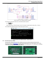
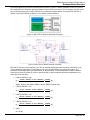
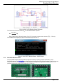
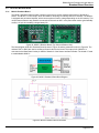
ROHM
Sensor
Evaluation
Kit
USER MANUAL
ROHM Sensor Evaluation Kit User Manual Rev0.0
Contents
Contents
1. General Information and Introduction .......................................................................................................................... 6
1.1. Introduction ............................................................................................................................................................. 6
1.2. Quick Start Guide.................................................................................................................................................... 6
1.3. Supported Sensor Products .................................................................................................................................... 7
2. Base Board Overview ..................................................................................................................................................... 8
2.1. Hardware ................................................................................................................................................................ 8
2.2. Software ................................................................................................................................................................ 12
3. Breakout Boards Overview.......................................................................................................................................... 13
3.1. Hall Sensor Breakout Boards ............................................................................................................................... 13
3.1.1. BU52004GUL Breakout Board.................................................................................................................... 13
3.1.2. BU52011HFV Breakout Board .................................................................................................................... 14
3.2. Ambient Light Sensor Breakout Boards................................................................................................................ 15
3.2.1. BH1620FVC Breakout Board ...................................................................................................................... 15
3.2.2. BH1710FVC Breakout Board ...................................................................................................................... 17
3.2.3. BH1730FVC Breakout Board ...................................................................................................................... 18
3.2.4. BH1721FVC Breakout Board ...................................................................................................................... 20
3.2.5. BH1780GLI Breakout Board ....................................................................................................................... 21
3.3. UV Sensor Breakout Board .................................................................................................................................. 23
3.3.1. ML8511 Breakout Board ............................................................................................................................. 23
3.4. MEM Sensor Breakout Boards ............................................................................................................................. 24
3.4.1. KX022 Breakout Board ............................................................................................................................... 24
3.4.2. KMX61 Breakout Board .............................................................................................................................. 26
3.5. Temperature Sensor Breakout Boards ................................................................................................................. 28
3.5.1. BD1020HFV Breakout Board ...................................................................................................................... 28
3.5.2. BDJ0601HFV Breakout Board .................................................................................................................... 29
3.5.3. BDE0600G Breakout Board ........................................................................................................................ 31
3.5.4. BDJ0550HFV Breakout Board .................................................................................................................... 32
Appendix A: Programming the Base Board Instruction ................................................................................................. 35
Page 2 of 37
ROHM Sensor Evaluation Kit User Manual
List of Figures
List of Figures
Figure 1: Sensor Evaluation Kit............................................................................................................................................... 6
Figure 2: Base Board and Breakout Board Connection .......................................................................................................... 6
Figure 3: PuTTy Configuration ................................................................................................................................................ 7
Figure 4: Base Board Sample Output without Breakout Board .............................................................................................. 7
Figure 5: Base Board Hardware Block Diagram ..................................................................................................................... 8
Figure 6: Base Board (Top View) ............................................................................................................................................ 8
Figure 7: Base Board - Q112 MCU Schematic ....................................................................................................................... 9
Figure 8: Base Board - Power Supply Schematic ................................................................................................................... 9
Figure 9: Base Board - Reset and Debugger Schematic ...................................................................................................... 10
Figure 10: Base Board - Sensor Interface Schematic .......................................................................................................... 10
Figure 11: Base Board - Feedback LEDs Schematic ........................................................................................................... 10
Figure 12: Base Board - USB to UART Schematic ............................................................................................................... 11
Figure 13: Base Board - Software Flow Diagram ................................................................................................................. 12
Figure 14: BU52004GUL Breakout Board (Top View and Bottom View) ............................................................................. 13
Figure 15: BU52004GUL Breakout Board Block Diagram .................................................................................................... 13
Figure 16: BU52004GUL Breakout Board Schematic .......................................................................................................... 13
Figure 17: BU52004GUL Breakout Board – Sample Output ................................................................................................ 14
Figure 18: BU52011HFV Breakout Board (Top View and Bottom View) .............................................................................. 14
Figure 19: BU52011HFV Breakout Board Block Diagram .................................................................................................... 14
Figure 20: BU52011HFV Breakout Board Schematic ........................................................................................................... 15
Figure 21: BU52011HFV Breakout Board – Sample Output ................................................................................................ 15
Figure 22: BH1620FVC Breakout Board (Top View and Bottom View) ................................................................................ 15
Figure 23: BH1620FVC Breakout Board Block Diagram ...................................................................................................... 16
Figure 24: BH1620FVC Breakout Board Schematic ............................................................................................................. 16
Figure 25: BH1620FVC Breakout Board – Sample Output .................................................................................................. 17
Figure 26: BH1710FVC Breakout Board (Top View and Bottom View) ................................................................................ 17
Figure 27: BH1710FVC Breakout Board Block Diagram ...................................................................................................... 17
Figure 28: BH1710FVC Breakout Board Schematic ............................................................................................................. 18
Figure 29: BH1710FVC Breakout Board – Sample Output .................................................................................................. 18
Figure 30: BH1730FVC Breakout Board (Top View and Bottom View) ................................................................................ 18
Figure 31: BH1730FVC Breakout Board Block Diagram ...................................................................................................... 19
Figure 32: BH1730FVC Breakout Board Schematic ............................................................................................................. 19
Figure 33: BH1730FVC Breakout Board – Sample Output .................................................................................................. 20
Figure 34: BH1721FVC Breakout Board (Top View and Bottom View) ................................................................................ 20
Figure 35: BH1721FVC Breakout Board Block Diagram ...................................................................................................... 20
Figure 36: BH1721FVC Breakout Board Schematic ............................................................................................................. 21
Figure 37: BH1721FVC Breakout Board – Sample Output .................................................................................................. 21
Figure 38: BH1780GLI Breakout Board (Top View and Bottom View) ................................................................................. 21
Figure 39: BH1780GLI Breakout Board Block Diagram ....................................................................................................... 22
Figure 40: BH1780GLI Breakout Board Schematic .............................................................................................................. 22
Figure 41: BH1780GLI Breakout Board – Sample Output .................................................................................................... 22
Figure 42: ML8511 Breakout Board (Top View and Bottom View) ....................................................................................... 23
Figure 43: ML8511 Breakout Board Block Diagram ............................................................................................................. 23
Figure 44: ML8511 Breakout Board Schematic .................................................................................................................... 23
Figure 45: ML8511 Breakout Board – Sample Output .......................................................................................................... 24
Figure 46: KX022 Breakout Board (Top View and Bottom View) ......................................................................................... 24
Figure 47: KX022 Breakout Board Block Diagram................................................................................................................ 25
Figure 48: KX022 Breakout Board Schematic ...................................................................................................................... 25
Figure 49: KX022 Breakout Board – Sample Output ............................................................................................................ 26
Figure 50: KMX61 Breakout Board (Top View and Bottom View) ........................................................................................ 26
Figure 51: KMX61 Breakout Board Block Diagram............................................................................................................... 26
Figure 52: KMX61 Breakout Board Schematic ..................................................................................................................... 27
Figure 53: KMX61 Breakout Board – Sample Output ........................................................................................................... 28
Figure 54: BD1020HFV Breakout Board (Top View and Bottom View) ................................................................................ 28
Figure 55: BD1020HFV Breakout Board Block Diagram ...................................................................................................... 28
Figure 56: BD1020HFV Breakout Board Schematic ............................................................................................................. 29
Figure 57: BD1020HFV Breakout Board – Sample Output .................................................................................................. 29
Figure 58: BDJ0601HFV Breakout Board (Top View and Bottom View) .............................................................................. 30
Page 3 of 37
ROHM Sensor Evaluation Kit User Manual
List of Figures
Figure 59: BDJ0601HFV Breakout Board Block Diagram .................................................................................................... 30
Figure 60: BDJ0601HFV Breakout Board Schematic ........................................................................................................... 30
Figure 61: BDJ0601HFV Breakout Board – Sample Output................................................................................................. 31
Figure 62: BDE0600G Breakout Board (Top View and Bottom View) .................................................................................. 31
Figure 63: BDE0600G Breakout Board Block Diagram ........................................................................................................ 31
Figure 64: BDE0600G Breakout Board Schematic ............................................................................................................... 32
Figure 65: BDE0600G Breakout Board – Sample Output .................................................................................................... 32
Figure 66: BDJ0550HFV Breakout Board (Top View and Bottom View) .............................................................................. 33
Figure 67: BDJ0550HFV Breakout Board Block Diagram .................................................................................................... 33
Figure 68: BDJ0550HFV Breakout Board Schematic ........................................................................................................... 33
Figure 69: BDJ0550HFV Breakout Board – Sample Output................................................................................................. 34
Figure 70: nanoEASE - Base Board Connection Diagram ................................................................................................... 35
Figure 71: nanoEASE - Base Board Connection .................................................................................................................. 35
Figure 72: DTU8 Debugger Settings ..................................................................................................................................... 36
Figure 73: DTU8 Debugger - Load software file into the Base Board .................................................................................. 36
Page 4 of 37
ROHM Sensor Evaluation Kit User Manual
List of Tables
List of Tables
Table 1: Supported Sensor Products ...................................................................................................................................... 7
Table 2: Base Board - Jumper/Switch Configurations ............................................................................................................ 8
Table 3: BH1620FVC Breakout Board - Gain Mode Configuration ...................................................................................... 16
Table 4: ML8511 Breakout Board – Jumper Positions ......................................................................................................... 24
Table 5: KX022 Breakout Board – Acceleration Sensitivity .................................................................................................. 25
Table 6: KMX61 Breakout Board – Acceleration Sensitivity ................................................................................................. 27
Table 7: BDE0600G Breakout Board – Jumper Positions .................................................................................................... 32
Page 5 of 37
ROHM Sensor Evaluation Kit User Manual
Introduction
1. General Information and Introduction
1.1.
Introduction
The Sensor Evaluation Kit is designed to test the functional operation of various sensor types. It includes one Base
board and several Breakout boards. The Base board is controller board with LAPIS MCU. The Breakout board is
sensor board which contains different kind of sensor IC.
The guide will help you understand how to connect Breakout board to Base board. It also shows how Base board
get data from sensor, then convert and display the result to computer screen.
Figure 1: Sensor Evaluation Kit
1.2.
Quick Start Guide
-
Step 1: Check and make sure your computer is installed driver to communicate with the Base board (LAPIS
MCU) via the USB interface. If not, please follow http://www.ftdichip.com/Support/Documents/InstallGuides.htm
to install driver.
-
Step 2: Check and set jumper default setting as following:
•
Power Selection Switch (J1) is in VBUS position (position 3).
•
Reset Selection Header (J2) is in USR_RST position (connect pin 1 and 2).
-
Step 3: Plug the Sensor Breakout board into the Base Board.
-
Step 4: Connect the Base board + Breakout board to computer via USB cable.
Figure 2: Base Board and Breakout Board Connection
-
Step 5: Run Serial Terminal tool (PuTTy), configure PuTTy run at Serial type with data rate is 9600bps .The
output data will be displayed on terminal screen. If there’s no output on terminal screen, please go to Appendix
A: Programming the Base Board Instruction to program/re-program the Base Board.
Page 6 of 37
ROHM Sensor Evaluation Kit User Manual
Introduction
Figure 3: PuTTy Configuration
Figure 4: Base Board Sample Output without Breakout Board
1.3.
Supported Sensor Products
No
Part Number
1
2
3
4
5
6
7
8
9
10
11
12
13
14
BU52004GUL
BU52011HFV
BH1620FVC
BH1710FVC
BH1730FVC
BH1721FVC
BH1780GLI
ML8511
KX022
KMX061
BD1020HFV
BDJ0601HFV
BDE0600G
BDJ0550HFV
Type
Hall Sensor
Ambient Light Sensor
UV Sensor
MEM Sensor
Temperature Sensor
Sensor Control Code
1
2
5
6
7
8
9
10
15
16
20
21
22
23
Table 1: Supported Sensor Products
Page 7 of 37
ROHM Sensor Evaluation Kit User Manual
Base Board Overview
2. Base Board Overview
2.1.
Hardware
The block diagram of the Base Board is show as Figure 5. The LAPIS MCU - ML610Q112 is used to interface with
the Breakout Board via Sensor Interface Headers and interface with PC via UART to USB IC – FT230XS-R.
Figure 5: Base Board Hardware Block Diagram
Figure 6: Base Board (Top View)
Designator
J1
J2
Position
Description
1 (EXT_PWR)
External Power Source selected
2 (OPEN)
No Power Source selected
3 (VBUS)
VBUS Source selected
2-1 (USR_RST)
User Reset selected
2-3 (nE_RST)
nanoEASE Reset selected
Table 2: Base Board - Jumper/Switch Configurations
Page 8 of 37
ROHM Sensor Evaluation Kit User Manual
Base Board Overview
The ML610Q112 is a high-performance 8-bit CMOS microcontroller into which rich peripheral circuits, such as
timers, PWM, UART, I2C bus interface (master/slave), synchronous serial port, voltage level supervisor analog
comparators and 10-bit successive approximation type A/D converter, are incorporated around 8-bit CPU nXU8/100. The CPU nX-U8/100 is capable of efficient instruction execution in 1-intruction 1-clock mode by pipe line
architecture parallel processing. The Flash ROM that is installed as program memory, and the on-chip debug
function that is installed, enable program debugging and programming on customer’s board.
Figure 7: Base Board - Q112 MCU Schematic
The Base Board is powered by VBUS of USB connector or External Power Source that connected via header J3.
The switch J1 is used to select power source of the board.
Figure 8: Base Board - Power Supply Schematic
Page 9 of 37
ROHM Sensor Evaluation Kit User Manual
Base Board Overview
The debugger functionality of ML610Q112 is very useful. You will be able to single-step through your code to
quickly find problems and solutions. You can set breakpoints and create and save watch lists of variables to help
you better understand what is going on inside your code. To manually reset the micro using the button S1, move J2
to the USR_RST position.
Figure 9: Base Board - Reset and Debugger Schematic
The Sensor Interface Headers
Figure 10: Base Board - Sensor Interface Schematic
The feedback LEDs
Figure 11: Base Board - Feedback LEDs Schematic
Page 10 of 37
ROHM Sensor Evaluation Kit User Manual
Base Board Overview
The UART to USB block
Figure 12: Base Board - USB to UART Schematic
Page 11 of 37
ROHM Sensor Evaluation Kit User Manual
Base Board Overview
2.2.
Software
The source code of the Base Board software can download from
https://github.com/ROHMUSDC/ROHMSensorPlatformEVK/
The flow diagram of the Base Board software is show in Figure 13. The “Sensor Control” value is input data of port
PD of ML610Q112. This value used to detect kind of Breakout Board that connected to the Base Board and defined
as Table 1.
Figure 13: Base Board - Software Flow Diagram
Page 12 of 37
ROHM Sensor Evaluation Kit User Manual
Breakout Board Overview
3. Breakout Boards Overview
3.1.
3.1.1.
Hall Sensor Breakout Boards
BU52004GUL Breakout Board
The BU52004GUL Breakout Board provides a simple environment to quickly evaluate performance of the
BU52004GUL sensor. The BU52004GUL is bipolar Hall IC incorporating a polarity determination circuit that
enables operation (output) on both the S- and N-poles, with the polarity judgment based on the output processing
configuration.
Figure 14: BU52004GUL Breakout Board (Top View and Bottom View)
The block diagram of BU52004GUL Breakout Board is show in Figure 15 and the schematic is show in Figure 16.
The resistors R155 to R160 are used to set Sensor Control value for the board. The output pins B1 and B2 of
BU52004GUL are connected to the Base Board via pins GPIO0 and GPIO1 of Header 1 of the Sensor Interface
Headers.
Figure 15: BU52004GUL Breakout Board Block Diagram
Figure 16: BU52004GUL Breakout Board Schematic
Page 13 of 37
ROHM Sensor Evaluation Kit User Manual
Breakout Board Overview
When BU52004GUL Breakout Board is connected to the running Base Board,
•
If no magnetic field present, all LEDs will be turn off and output text which is sent to PC via UART is “Hall
– No Mag Fields Detected.”.
•
If South-Pole magnetic field present, LED 0 will be turn on and output text is “Hall – South Mag Field
Detected.”.
•
If North-Pole magnetic field present, LED 7 will be turn on and output text is “Hall – North Mag Field
Detected.”.
Figure 17: BU52004GUL Breakout Board – Sample Output
3.1.2.
BU52011HFV Breakout Board
The BU52011HFV Breakout Board provides a simple environment to quickly evaluate performance of the
BU52011HFV sensor. The BU52011HFV is magnetic switches that can operate both S-and N-pole, upon which
the output goes from Hi to Low.
Figure 18: BU52011HFV Breakout Board (Top View and Bottom View)
The block diagram of BU52011HFV Breakout Board is show in Figure 19 and the schematic is show in Figure 20.
The resistors R161 to R166 are used to set Sensor Control value for the board. The output pin 5 of BU52011HFV
is connected to the Base Board via pin GPIO0 of Header 1 of the Sensor Interface Headers.
Figure 19: BU52011HFV Breakout Board Block Diagram
Page 14 of 37
ROHM Sensor Evaluation Kit User Manual
Breakout Board Overview
Figure 20: BU52011HFV Breakout Board Schematic
When BU52011HFV Breakout Board is connected to the running Base Board,
•
If no magnetic field present, all LEDs will be turn off and output text which is sent to PC via UART is “Hall
– No Mag Fields Detected.”.
•
If magnetic field present, LED 0 will be turn on and output text is “Hall – Mag Field Detected.”.
Figure 21: BU52011HFV Breakout Board – Sample Output
3.2.
3.2.1.
Ambient Light Sensor Breakout Boards
BH1620FVC Breakout Board
The BH1620FVC Breakout Board provides a simple environment to quickly evaluate performance of the
BH1620FVC sensor. The BH1620FVC is an analog current output ambient light sensor. This IC is the most
suitable to obtain the ambient light data for adjusting LCD and Keypad backlight of Mobile phone for power saving
and better visibility.
Figure 22: BH1620FVC Breakout Board (Top View and Bottom View)
Page 15 of 37
ROHM Sensor Evaluation Kit User Manual
Breakout Board Overview
The block diagram of BH1620FVC Breakout Board is show in Figure 23 and the schematic is show in Figure 24.
The resistors R167 to R172 are used to set Sensor Control value for the board. The Gain Mode can be set by
stuffing resistors R128 to R131 follow Table 3. The output pin 5 of BH1620FVC is connected to the Base Board
via pin ADC0 of Header 2 of the Sensor Interface Headers. The Base Board detects Gain Mode configuration by
reading the pins GPIO0 and GPIO1 of Header 1 of the Sensor Interface Headers.
Figure 23: BH1620FVC Breakout Board Block Diagram
Figure 24: BH1620FVC Breakout Board Schematic
Mode
Install
Not Install
GC1
GC2
Shutdown
H-Gain (default)
M-Gain
L-Gain
R128,R130
R129,R130
R128,R131
R129,R131
R129,R131
R128,R131
R129,R130
R128,R130
0
0
1
1
0
1
0
1
Illuminance
Detection Range
~1,000
~10,000
~100,000
Table 3: BH1620FVC Breakout Board - Gain Mode Configuration
Based on the Gain Mode that read from pins GPIO0 and GPIO1 of Header 1 and 10bit ADC value that converted
on pin ADC0 of Header 2 of the Sensor Interface Headers, the illuminance of the ALS surface (EV) is calculated
as bellow equation:
•
H-Gain Mode
𝐄𝐕 =
𝐕
[𝐥𝐱]
𝟎. 𝟓𝟕 × 𝟏𝟎−𝟔 × 𝐑 𝟏𝟑𝟐
Where: V is output voltage of output pin of BH1620FVC. R132 = 5.6kΩ
•
M-Gain Mode
•
𝐄𝐕 =
𝐕
[𝐥𝐱]
𝟎. 𝟎𝟓𝟕 × 𝟏𝟎−𝟔 × 𝐑 𝟏𝟑𝟐
𝐄𝐕 =
𝐕
[𝐥𝐱]
𝟎. 𝟎𝟎𝟓𝟕 × 𝟏𝟎−𝟔 × 𝐑 𝟏𝟑𝟐
L-Gain Mode
Page 16 of 37
ROHM Sensor Evaluation Kit User Manual
Breakout Board Overview
The feedback LEDs display 8bit ADC value that scaled from 10bit ADC of output pin of BH1620FVC by right shift
2bit.
Figure 25: BH1620FVC Breakout Board – Sample Output
3.2.2.
BH1710FVC Breakout Board
The BH1710FVC Breakout Board provides a simple environment to quickly evaluate performance of the
BH1710FVC sensor. The BH1710FVC is a digital Ambient Light Sensor IC for I2C bus interface. This IC is the
most suitable to obtain the ambient light data for adjusting LCD and Keypad backlight power of Mobile phone. It is
possible to detect wide range at High resolution (1-65535 lx).
Figure 26: BH1710FVC Breakout Board (Top View and Bottom View)
The block diagram of BH1620FVC Breakout Board is show in Figure 27 and the schematic is show in Figure 28.
The resistors R173 to R178 are used to set Sensor Control value for the board. The I2C interface pins of
BH1620FVC (pin 4 and pin 6) are connected to the Base Board via the pins SDA and SCL of Header 2 of the
Sensor Interface Headers.
Figure 27: BH1710FVC Breakout Board Block Diagram
Page 17 of 37
ROHM Sensor Evaluation Kit User Manual
Breakout Board Overview
Figure 28: BH1710FVC Breakout Board Schematic
The illuminance of the ALS surface (EV) is calculated as bellow equation:
𝐄𝐕 =
𝐑𝐚𝐰 𝐃𝐚𝐭𝐚
[𝐥𝐱]
𝐀𝐜𝐜𝐮𝐫𝐚𝐜𝐲
Where: Raw Data is 16bit serial output of the ALS. Accuracy is measurement accuracy (Typ. 1.2 times)
The feedback LEDs display high byte of 16bit serial output of the ALS.
Figure 29: BH1710FVC Breakout Board – Sample Output
3.2.3.
BH1730FVC Breakout Board
The BH1730FVC Breakout Board provides a simple environment to quickly evaluate performance of the
BH1730FVC sensor. The BH1730FVC is a digital Ambient Light Sensor IC for I2C bus interface. This IC is the
most suitable to obtain the ambient light data for adjusting LCD backlight power of TV, mobile phone. It is possible
to detect very wide range light intensity (0.008-65535 lx).
Figure 30: BH1730FVC Breakout Board (Top View and Bottom View)
Page 18 of 37
ROHM Sensor Evaluation Kit User Manual
Breakout Board Overview
The block diagram of BH1730FVC Breakout Board is show in Figure 31 and the schematic is show in Figure 32.
The resistors R179 to R184 are used to set Sensor Control value for the board. The I2C interface pins (pin 4 and
pin 6) and interrupt pin (pin 2) of BH1730FVC are connected to the Base Board via the pins SDA and SCL of
Header 2 and the pin GPIO0 of Header 1 of the Sensor Interface Headers.
Figure 31: BH1730FVC Breakout Board Block Diagram
Figure 32: BH1730FVC Breakout Board Schematic
BH1730FVC has two outputs, DATA0 (14h, 15h) for detecting visible light and infrared light, and DATA1 (16h,
17h) for detecting infrared light. The illuminance value can be calculated by using these two outputs. The
calculation formula depends on the characteristic of optical window. The bellow equation is used to calculate
illuminance of the ALS surface (EV) with no optical window or optical window that has flat transmittance from
visible light to infrared light.
•
If DATA1/DATA0 < 0.26
𝐄𝐕 =
(𝟏. 𝟐𝟗𝟎 × 𝐃𝐀𝐓𝐀𝟎 − 𝟐. 𝟕𝟑𝟑 × 𝐃𝐀𝐓𝐀𝟏) 𝟏𝟎𝟎𝐦𝐬
×
[𝐥𝐱]
𝐆𝐀𝐈𝐍
𝐈𝐓𝐈𝐌𝐄
Where: GAIN is Gain Mode. ITIME is value of TIMING register (01h)
•
If DATA1/DATA0 < 0.55
•
𝐄𝐕 =
If DATA1/DATA0 < 1.09
•
𝐄𝐕 =
If DATA1/DATA0 < 2.13
•
𝐄𝐕 =
(𝟎. 𝟕𝟗𝟓 × 𝐃𝐀𝐓𝐀𝟎 − 𝟎. 𝟖𝟓𝟗 × 𝐃𝐀𝐓𝐀𝟏) 𝟏𝟎𝟎𝐦𝐬
×
[𝐥𝐱]
𝐆𝐀𝐈𝐍
𝐈𝐓𝐈𝐌𝐄
(𝟎. 𝟓𝟏𝟎 × 𝐃𝐀𝐓𝐀𝟎 − 𝟎. 𝟑𝟒𝟓 × 𝐃𝐀𝐓𝐀𝟏) 𝟏𝟎𝟎𝐦𝐬
×
[𝐥𝐱]
𝐆𝐀𝐈𝐍
𝐈𝐓𝐈𝐌𝐄
(𝟎. 𝟐𝟕𝟔 × 𝐃𝐀𝐓𝐀𝟎 − 𝟎. 𝟏𝟑𝟎 × 𝐃𝐀𝐓𝐀𝟏) 𝟏𝟎𝟎𝐦𝐬
×
[𝐥𝐱]
𝐆𝐀𝐈𝐍
𝐈𝐓𝐈𝐌𝐄
Other
𝐄𝐕 = 𝟎 [𝐥𝐱]
Page 19 of 37
ROHM Sensor Evaluation Kit User Manual
Breakout Board Overview
The feedback LEDs display high byte of output DATA0.
Figure 33: BH1730FVC Breakout Board – Sample Output
3.2.4.
BH1721FVC Breakout Board
The BH1721FVC Breakout Board provides a simple environment to quickly evaluate performance of the
BH1721FVC sensor. The BH1721FVC is a digital Ambient Light Sensor IC for I2C bus interface. This IC is the
most suitable to obtain the ambient light data for adjusting LCD and Keypad backlight power of Mobile phone. It is
possible to detect wide range at High resolution (1-65528 lx).
Figure 34: BH1721FVC Breakout Board (Top View and Bottom View)
The block diagram of BH1721FVC Breakout Board is show in Figure 35 and the schematic is show in Figure 36.
The resistors R185 to R190 are used to set Sensor Control value for the board. The I2C interface pins of
BH1721FVC (pin 3 and pin 5) are connected to the Base Board via the pins SDA and SCL of Header 2 of the
Sensor Interface Headers.
Figure 35: BH1721FVC Breakout Board Block Diagram
Page 20 of 37
ROHM Sensor Evaluation Kit User Manual
Breakout Board Overview
Figure 36: BH1721FVC Breakout Board Schematic
The illuminance of the ALS surface (EV) is calculated as bellow equation:
𝐄𝐕 =
𝐑𝐚𝐰 𝐃𝐚𝐭𝐚
[𝐥𝐱]
𝐀𝐜𝐜𝐮𝐫𝐚𝐜𝐲
Where: Raw Data is 16bit serial output of the ALS. Accuracy is measurement accuracy (Typ. 1.2 times)
The feedback LEDs display high byte of 16bit serial output of the ALS.
Figure 37: BH1721FVC Breakout Board – Sample Output
3.2.5.
BH1780GLI Breakout Board
The BH1780GLI Breakout Board provides a simple environment to quickly evaluate performance of the
BH1780GLI sensor. The BH1780GLI is a digital Ambient Light Sensor IC for I2C bus interface. This IC is the most
suitable to obtain the ambient light data for adjusting LCD and Keypad backlight power of Mobile phone. It is
possible to detect wide range at High resolution (1-65535 lx).
Figure 38: BH1780GLI Breakout Board (Top View and Bottom View)
Page 21 of 37
ROHM Sensor Evaluation Kit User Manual
Breakout Board Overview
The block diagram of BH1780GLI Breakout Board is show in Figure 39 and the schematic is show in Figure 40.
The resistors R191 to R196 are used to set Sensor Control value for the board. The I2C interface pins of
BH1780GLI (pin 3 and pin 4) are connected to the Base Board via the pins SDA and SCL of Header 2 of the
Sensor Interface Headers.
Figure 39: BH1780GLI Breakout Board Block Diagram
Figure 40: BH1780GLI Breakout Board Schematic
The illuminance of the ALS surface (EV) is calculated as bellow equation:
𝐄𝐕 =
𝐑𝐚𝐰 𝐃𝐚𝐭𝐚
[𝐥𝐱]
𝐀𝐜𝐜𝐮𝐫𝐚𝐜𝐲
Where: Raw Data is 16bit serial output of the ALS. Accuracy is measurement accuracy (Typ. 1.0 times)
The feedback LEDs display high byte of 16bit serial output of the ALS.
Figure 41: BH1780GLI Breakout Board – Sample Output
Page 22 of 37
ROHM Sensor Evaluation Kit User Manual
Breakout Board Overview
3.3.
3.3.1.
UV Sensor Breakout Board
ML8511 Breakout Board
The ML8511 Breakout Board provides a simple environment to quickly evaluate performance of the ML8511
sensor. The ML8511 is a UV sensor, which is suitable for acquiring UV intensity indoors or outdoors. The ML8511
is equipped with an internal amplifier, which converts photo-current to voltage depending on the UV intensity. This
unique feature offers an easy interface to external circuits such as ADC. In the power down mode, typical standby
current is 0.1µA, thus enabling a longer battery life.
Figure 42: ML8511 Breakout Board (Top View and Bottom View)
The block diagram of ML8511 Breakout Board is show in Figure 43 and the schematic is show in Figure 44. The
resistors R197 to R202 are used to set Sensor Control value for the board. The output pin 8 of ML8511 is
connected to the Base Board via the pin ADC0 of Header 2 of the Sensor Interface Headers. The header J7 used
to enable/disable ML8511.
Figure 43: ML8511 Breakout Board Block Diagram
Figure 44: ML8511 Breakout Board Schematic
Page 23 of 37
ROHM Sensor Evaluation Kit User Manual
Breakout Board Overview
Designator
Position
Description
J7
2-1
2-3
Enable ML8511 (U59)
Disable ML8511 (U59)
Table 4: ML8511 Breakout Board – Jumper Positions
The UV Intensity of UV sensor surface (UVI) is calculated as bellow equation:
𝐔𝐕𝐈 =
𝐕 − 𝟐. 𝟐
+ 𝟏𝟎 [𝐦𝐖/𝐜𝐦𝟐 ]
𝟎. 𝟏𝟐𝟗
Where: V is output voltage of output pin of ML8511.
The feedback LEDs display 8bit ADC value that scaled from 10bit ADC of output pin of ML8511 by right shift 2bit.
Figure 45: ML8511 Breakout Board – Sample Output
3.4.
3.4.1.
MEM Sensor Breakout Boards
KX022 Breakout Board
The KX022 Breakout Board provides a simple environment to quickly evaluate performance of the KX022 sensor.
The KX022 is a robust, low-power, I2C/SPI, 3-axis accelerometer with integrated FIFO/FILO buffer that features a
wide range of embedded functionality, including tap detection, orientation, activity, and wake-up algorithms.
Kionix’s XAC sensor provides outstanding stability with a market-leading combination of improved shock, reflow,
and thermal performance. The KX022 also offers accelerometer outputs with up to 16-bit resolution for greater
precision. User-selectable parameters include ± 2g, 4g or 8g ranges and Output Data Rates (ODR) with
programmable high-pass and low-pass filters. It is packaged in an ultra-small, 12-pin, 2x2x0.9mm LGA plastic
package.
Figure 46: KX022 Breakout Board (Top View and Bottom View)
The block diagram of KX022 Breakout Board is show in Figure 47 and the schematic is show in Figure 48. The
resistors R203 to R208 are used to set Sensor Control value for the board. The I2C interface pins (pin 2 and pin
12) and interrupt pins (pin 5 and pin 6) of KX022 are connected to the Base Board via the pins SDA and SCL of
Header 2 and pins GPIO0 and GPIO1 of Header 1 of the Sensor Interface Headers.
Page 24 of 37
ROHM Sensor Evaluation Kit User Manual
Breakout Board Overview
Figure 47: KX022 Breakout Board Block Diagram
Figure 48: KX022 Breakout Board Schematic
The accelerations (X, Y and Z) of the KX022 are calculated as bellow equation:
𝐗=
𝐗𝐎𝐔𝐓
[𝐠]
𝐒𝐞𝐧𝐬𝐢𝐭𝐢𝐯𝐢𝐭𝐲
𝐙=
𝐙𝐎𝐔𝐓
[𝐠]
𝐒𝐞𝐧𝐬𝐢𝐭𝐢𝐯𝐢𝐭𝐲
𝐘=
𝐘𝐎𝐔𝐓
[𝐠]
𝐒𝐞𝐧𝐬𝐢𝐭𝐢𝐯𝐢𝐭𝐲
Where: XOUT is X-axis accelerometer output XOUT_L (06h) and XOUT_H (07h).
YOUT is Y-axis accelerometer output YOUT_L (08h) and YOUT_H (09h).
ZOUT is Z-axis accelerometer output ZOUT_L (0Ah) and ZOUT_H (0Bh).
Resolution
[bits]
16
8
Range
± 2g
± 4g
± 8g
± 2g
± 4g
± 8g
Sensitivity (Typ.)
[counts/g]
16384
8192
4096
64
32
16
Table 5: KX022 Breakout Board – Acceleration Sensitivity
Page 25 of 37
ROHM Sensor Evaluation Kit User Manual
Breakout Board Overview
In default software, the KX022 is configured to operate at 16bit resolution and ± 2g.
The feedback LEDs displays tilt position of the KX022 surface:
•
If tilt position is Face-Up State, LED 3 will be turn on.
•
If tilt position is Face-Down State, LED 4 will be turn on.
•
If tilt position is Left State, LED 7 will be turn on.
•
If tilt position is Right State, LED 0 will be turn on.
•
If tilt position is Up State, LED 5 will be turn on.
•
If tilt position is Down State, LED 2 will be turn on.
Figure 49: KX022 Breakout Board – Sample Output
3.4.2.
KMX61 Breakout Board
The KMX61 Breakout Board provides a simple environment to quickly evaluate performance of the KMX61
sensor. The KMX61 is a 6-axis E-compass device with auto-calibration software. The KMX61 delivers high
sensitivity (0.05 µT/count) with stability over temperature (± 0.05 %/ºC) and is well-suited for a range of
smartphone, tablet and health and fitness applications.
Figure 50: KMX61 Breakout Board (Top View and Bottom View)
The block diagram of KMX61 Breakout Board is show in Figure 51 and the schematic is show in Figure 52. The
resistors R209 to R214 are used to set Sensor Control value for the board. The I2C interface pins (pin 6 and pin
4) and interrupt pins (pin 11 and pin 9) of KMX61 are connected to the Base Board via the pins SDA and SCL of
Header 2 and pins GPIO0 and GPIO1 of Header 1 of the Sensor Interface Headers.
Figure 51: KMX61 Breakout Board Block Diagram
Page 26 of 37
ROHM Sensor Evaluation Kit User Manual
Breakout Board Overview
Figure 52: KMX61 Breakout Board Schematic
The accelerations (X, Y and Z) of the KMX61 are calculated as bellow equation:
𝐀𝐂𝐂𝐄𝐋𝐗 =
𝐀𝐂𝐂𝐄𝐋_𝐗𝐎𝐔𝐓
[𝐠]
𝐒𝐞𝐧𝐬𝐢𝐭𝐢𝐯𝐢𝐭𝐲
𝐀𝐂𝐂𝐄𝐋𝐙 =
𝐀𝐂𝐂𝐄𝐋_𝐙𝐎𝐔𝐓
[𝐠]
𝐒𝐞𝐧𝐬𝐢𝐭𝐢𝐯𝐢𝐭𝐲
𝐀𝐂𝐂𝐄𝐋𝐘 =
𝐀𝐂𝐂𝐄𝐋_𝐘𝐎𝐔𝐓
[𝐠]
𝐒𝐞𝐧𝐬𝐢𝐭𝐢𝐯𝐢𝐭𝐲
Where: ACCEL_XOUT is X-axis accelerometer output ACCEL_XOUT_L (0Ah) and ACCEL_XOUT_H (0Bh).
ACCEL_YOUT is Y-axis accelerometer output ACCEL_YOUT_L (0Ch) and ACCEL_YOUT_H (0Dh).
ACCEL_ZOUT is Z-axis accelerometer output ACCEL_ZOUT_L (0Eh) and ACCEL_ZOUT_H (0Fh).
Resolution
[bits]
14
12
Range
± 8g
± 2g
± 4g
± 8g
Sensitivity (Typ.)
[counts/g]
1024
1024
512
256
Table 6: KMX61 Breakout Board – Acceleration Sensitivity
In default software, the KMX61 is configured to operate at 14bit resolution and ± 2g.
The magnetics (X, Y and Z) of the KMX61 are calculated as bellow equation:
𝐌𝐀𝐆𝐗 = 𝐌𝐀𝐆_𝐗𝐎𝐔𝐓 × 𝐒𝐞𝐧𝐬𝐢𝐭𝐢𝐯𝐢𝐭𝐲 [𝛍𝐓]
𝐌𝐀𝐆𝐘 = 𝐌𝐀𝐆_𝐘𝐎𝐔𝐓 × 𝐒𝐞𝐧𝐬𝐢𝐭𝐢𝐯𝐢𝐭𝐲 [𝛍𝐓]
𝐌𝐀𝐆𝐙 = 𝐌𝐀𝐆_𝐙𝐎𝐔𝐓 × 𝐒𝐞𝐧𝐬𝐢𝐭𝐢𝐯𝐢𝐭𝐲 [𝛍𝐓]
Where: MAG_XOUT is X-axis magnetometer output MAG _XOUT_L (12h) and MAG _XOUT_H (13h).
MAG _YOUT is Y-axis magnetometer output MAG _YOUT_L (14h) and MAG _YOUT_H (15h).
MAG _ZOUT is Z-axis magnetometer output MAG _ZOUT_L (16h) and MAG _ZOUT_H (16h).
Sensitivity is Magnetic Sensitivity (Typ. 0.146 µT/count)
Page 27 of 37
ROHM Sensor Evaluation Kit User Manual
Breakout Board Overview
The feedback LEDs displays tilt position of the KX022 surface:
•
If tilt position is Face-Up State, LED 3 will be turn on.
•
If tilt position is Face-Down State, LED 4 will be turn on.
•
If tilt position is Left State, LED 7 will be turn on.
•
If tilt position is Right State, LED 0 will be turn on.
•
If tilt position is Up State, LED 5 will be turn on.
•
If tilt position is Down State, LED 2 will be turn on.
Figure 53: KMX61 Breakout Board – Sample Output
3.5.
3.5.1.
Temperature Sensor Breakout Boards
BD1020HFV Breakout Board
The BD1020HFV Breakout Board provides a simple environment to quickly evaluate performance of the
BD1020HFV sensor. The BD1020HFV is a low quiescent current (4μA) and high accuracy temperature sensor,
detecting temperature by itself, output voltage appears linearly along the temperature.
Figure 54: BD1020HFV Breakout Board (Top View and Bottom View)
The block diagram of BD1020HFV Breakout Board is show in Figure 55 and the schematic is show in Figure 56.
The resistors R215 to R220 are used to set Sensor Control value for the board. The output pin VOUT (pin 3) of
BD1020HFV is connected to the Base Board via the pin ADC0 of Header 2 of the Sensor Interface Headers.
Figure 55: BD1020HFV Breakout Board Block Diagram
Page 28 of 37
ROHM Sensor Evaluation Kit User Manual
Breakout Board Overview
Figure 56: BD1020HFV Breakout Board Schematic
The temperature of BD1020HFV sensor is calculated as bellow equation:
𝐓𝐞𝐦𝐩 =
𝐕 − 𝑽𝟎
+ 𝐓𝐞𝐦𝐩𝟎 [℃]
𝐒𝐞𝐧𝐬𝐢𝐭𝐢𝐯𝐢𝐭𝐲
Where: V is output voltage of output pin of BD1020HFV. V0 is output voltage of output pin of BD1020HFV at
Temp0 (1.3V@30°C). Sensitivity is temperature sensitivity (Typ. -8.2 mV/°C).
The feedback LEDs display 8bit ADC value that scaled from 10bit ADC of output pin of BD1020HFV by right shift
2bit.
Figure 57: BD1020HFV Breakout Board – Sample Output
3.5.2.
BDJ0601HFV Breakout Board
The BDJ0601HFV Breakout Board provides a simple environment to quickly evaluate performance of the
BDJ0601HFV sensor. The BDJ0601HFV is thermostat output temperature sensor IC with built-in temperature
detection element, constant current circuit and high-accuracy reference voltage source in one chip. Temperature
detection can be realized at ±2.5℃accuracy without complicated design. It is the best temperature sensor IC for a
portable equipment of micro and low current, the power down function, and the battery drive. It is possible to use
it for a wide usage such as the heat detection and temperature monitors because it provides with the analog
output in addition to the thermostat power output.
Page 29 of 37
ROHM Sensor Evaluation Kit User Manual
Breakout Board Overview
Figure 58: BDJ0601HFV Breakout Board (Top View and Bottom View)
The block diagram of BDJ0601HFV Breakout Board is show in Figure 59 and the schematic is show in Figure 60.
The resistors R221 to R226 are used to set Sensor Control value for the board. The output pin VTEMP (pin 1)
and digital thermostat output pin OS (pin 4) of BDJ0601HFV are connected to the Base Board via the pin ADC0 of
Header 2 and pin GPIO0 of Header 1 of the Sensor Interface Headers.
Figure 59: BDJ0601HFV Breakout Board Block Diagram
Figure 60: BDJ0601HFV Breakout Board Schematic
The temperature of BDJ0601HFV sensor is calculated as bellow equation:
𝐓𝐞𝐦𝐩 =
𝐕 − 𝑽𝟎
+ 𝐓𝐞𝐦𝐩𝟎 [℃]
𝐒𝐞𝐧𝐬𝐢𝐭𝐢𝐯𝐢𝐭𝐲
Where: V is output voltage of output pin of BDJ0601HFV. V0 is output voltage of output pin of BDJ0601HFV at
Temp0 (1.3V@30°C). Sensitivity is temperature sensitivity (Typ. -8.2 mV/°C).
The feedback LEDs display 8bit ADC value that scaled from 10bit ADC of output pin of BDJ0601HFV by right shift
2bit.
Page 30 of 37
ROHM Sensor Evaluation Kit User Manual
Breakout Board Overview
Figure 61: BDJ0601HFV Breakout Board – Sample Output
3.5.3.
BDE0600G Breakout Board
The BDE0600G Breakout Board provides a simple environment to quickly evaluate performance of the
BDE0600G sensor. The BDE0600G is a low quiescent current (16μA), high accuracy thermostat (temperature
switch) IC. The BDE0600G built in temperature sensor, reference voltage regulator, D/A converter, and
comparator. Detecting temperature by itself, OS terminal state is changed at logically. Open Drain Output (Active
L) is available in BDE0600G.
Figure 62: BDE0600G Breakout Board (Top View and Bottom View)
The block diagram of BDE0600G Breakout Board is show in Figure 63 and the schematic is show in Figure 64.
The resistors R233 to R238 are used to set Sensor Control value for the board. The output pin VTEMP (pin 3)
and digital thermostat output pin OS (pin 5) of BDE0600G are connected to the Base Board via the pin ADC0 of
Header 2 and pin GPIO0 of Header 1 of the Sensor Interface Headers. The header J6 is used to set detection
temperature.
Figure 63: BDE0600G Breakout Board Block Diagram
Page 31 of 37
ROHM Sensor Evaluation Kit User Manual
Breakout Board Overview
Figure 64: BDE0600G Breakout Board Schematic
Designator
J6
Position
Detection Temperature (°C)
Open
2-1
2-3
65
60
55
Table 7: BDE0600G Breakout Board – Jumper Positions
The temperature of BDE0600G sensor is calculated as bellow equation:
𝐓𝐞𝐦𝐩 =
𝐕 − 𝑽𝟎
+ 𝐓𝐞𝐦𝐩𝟎 [℃]
𝐒𝐞𝐧𝐬𝐢𝐭𝐢𝐯𝐢𝐭𝐲
Where: V is output voltage of output pin of BDE0600G. V0 is output voltage of output pin of BDE0600G at
Temp0 (1.753 V@30°C). Sensitivity is temperature sensitivity (Typ. -10.68 mV/°C).
The feedback LEDs display 8bit ADC value that scaled from 10bit ADC of output pin of BDE0600G by right shift
2bit.
Figure 65: BDE0600G Breakout Board – Sample Output
3.5.4.
BDJ0550HFV Breakout Board
The BDJ0550HFV Breakout Board provides a simple environment to quickly evaluate performance of the
BDJ0550HFV sensor. The BDJ0550HFV is thermostat output temperature sensor IC with built-in temperature
detection element, constant current circuit, and high-accuracy reference voltage source in one chip. Temperature
detection can be realized at ±2.5℃ accuracy without complicated design. It is the best temperature sensor IC for a
portable equipment of micro and low current, the power down function, and the battery drive. It is possible to use
it for a wide usage such as the heat detection and temperature monitors because it provides with the analog
output in addition to the thermostat power output.
Page 32 of 37
ROHM Sensor Evaluation Kit User Manual
Breakout Board Overview
Figure 66: BDJ0550HFV Breakout Board (Top View and Bottom View)
The block diagram of BDJ0550HFV Breakout Board is show in Figure 67 and the schematic is show in Figure 68.
The resistors R227 to R232 are used to set Sensor Control value for the board. The output pin VTEMP (pin 1)
and digital thermostat output pin OS (pin 5) of BDJ0550HFV are connected to the Base Board via the pin ADC0 of
Header 2 and pin GPIO0 of Header 1 of the Sensor Interface Headers.
Figure 67: BDJ0550HFV Breakout Board Block Diagram
Figure 68: BDJ0550HFV Breakout Board Schematic
The temperature of BDJ0550HFV sensor is calculated as bellow equation:
𝐓𝐞𝐦𝐩 =
𝐕 − 𝑽𝟎
+ 𝐓𝐞𝐦𝐩𝟎 [℃]
𝐒𝐞𝐧𝐬𝐢𝐭𝐢𝐯𝐢𝐭𝐲
Where: V is output voltage of output pin of BDJ0550HFV. V0 is output voltage of output pin of BDJ0601HFV at
Temp0 (1.3V@30°C). Sensitivity is temperature sensitivity (Typ. -8.2 mV/°C).
The feedback LEDs display 8bit ADC value that scaled from 10bit ADC of output pin of BDJ0550HFV by right shift
2bit.
Page 33 of 37
ROHM Sensor Evaluation Kit User Manual
Breakout Board Overview
Figure 69: BDJ0550HFV Breakout Board – Sample Output
Page 34 of 37
ROHM Sensor Evaluation Kit User Manual
Appendix A: Programming the Base Board Instruction
Appendix A: Programming the Base Board Instruction
This appendix explain how to program default software into Base Board using DTU8 Debugger.
-
Step 1: If the U8 Code Development tools are not installed on your PC, please install the U8 Code Development
tools from the CD included with the nanoEASE. (The U8Dev Suite includes 18 manuals to help you become
familiar with LAPIS’ micros, the development tools, the nanoEASE debugger, and more). Follow the instructions
in the ReleaseNote_e.pdf while installing the tools.
The tools provided with this kit may not be the most up to date. To get the latest LAPIS U8 Dev. Suite go to this
website and register and download the latest version of the tools: https://www.lapissemi.com/customer/lpmcu/login.html.
-
Step 2: Download the source code from https://github.com/ROHMUSDC/ROHMSensorPlatformEVK/. The default
software is stored in directory “Q112 Firmware - Sensor Platform EVK\_output\_hex\Q112SENSORPLATFORMEVK.HEX”.
-
Step 3: Connect the nanoEASE to the board as bellow diagram. Change Reset Selection Header (J2) to nE_RST
position (connect pin 2 and 3).
Figure 70: nanoEASE - Base Board Connection Diagram
Figure 71: nanoEASE - Base Board Connection
-
Step 4: Start the DTU8 Debugger by click on icon that placed at Start → All Programs → U8 Tools → nX-U8 →
DTU8 Debugger.
-
Step 5: In Target Settings window, select ML610112 in the Target chip field and nanoEASE in the Target ICE
Page 35 of 37
ROHM Sensor Evaluation Kit User Manual
Appendix A: Programming the Base Board Instruction
field.
Figure 72: DTU8 Debugger Settings
-
Step 6: Load default software into the Base Board by click on Load Program File button and select default
software file.
Figure 73: DTU8 Debugger - Load software file into the Base Board
Page 36 of 37
ROHM Sensor Evaluation Kit User Manual
Notes
Notes
No copying or reproduction of this document, in part or in whole, is permitted without the consent of
ROHM Co.,Ltd.
The content specified herein is subject to change for improvement without notice.
The content specified herein is for the purpose of introducing ROHM's products (hereinafter
"Products"). If you wish to use any such Product, please be sure to refer to the specifications, which
can be obtained from ROHM upon request.
Examples of application circuits, circuit constants and any other information contained herein
illustrate the standard usage and operations of the Products. The peripheral conditions must be
taken into account when designing circuits for mass production.
Great care was taken in ensuring the accuracy of the information specified in this document.
However, should you incur any damage arising from any inaccuracy or misprint of such information,
ROHM shall bear no responsibility for such damage.
The technical information specified herein is intended only to show the typical functions of and
examples of application circuits for the Products. ROHM does not grant you, explicitly or implicitly,
any license to use or exercise intellectual property or other rights held by ROHM and other parties.
ROHM shall bear no responsibility whatsoever for any dispute arising from the use of such technical
information.
The Products specified in this document are intended to be used with general-use electronic
equipment or devices (such as audio visual equipment, office-automation equipment,
communication devices, electronic appliances and amusement devices).
The Products specified in this document are not designed to be radiation tolerant.
While ROHM always makes efforts to enhance the quality and reliability of its Products, a Product
may fail or malfunction for a variety of reasons.
Please be sure to implement in your equipment using the Products safety measures to guard
against the possibility of physical injury, fire or any other damage caused in the event of the failure
of any Product, such as derating, redundancy, fire control and fail-safe designs. ROHM shall bear
no responsibility whatsoever for your use of any Product outside of the prescribed scope or not in
accordance with the instruction manual.
The Products are not designed or manufactured to be used with any equipment, device or system
which requires an extremely high level of reliability the failure or malfunction of which may result in a
direct threat to human life or create a risk of human injury (such as a medical instrument,
transportation equipment, aerospace machinery, nuclear-reactor controller, fuel-controller or other
safety device). ROHM shall bear no responsibility in any way for use of any of the Products for the
above special purposes. If a Product is intended to be used for any such special purpose, please
contact a ROHM sales representative before purchasing.
If you intend to export or ship overseas any Product or technology specified herein that may be
controlled under the Foreign Exchange and the Foreign Trade Law, you will be required to obtain a
license or permit under the Law.
Thank you for your accessing to ROHM product information.
More detail product information and catalogs are available, please contact us.
ROHM Customer Support System
http://www.rohm.com/contact/
Page 37 of 37