1
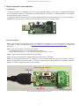
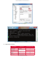
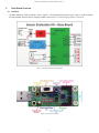
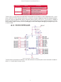
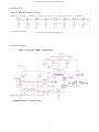
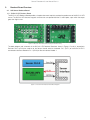
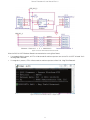
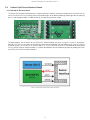
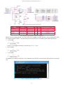
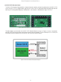
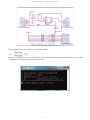
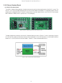
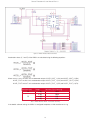
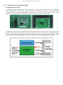
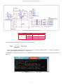
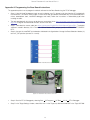
Sensor
Evaluation Kit
USER MANUAL
Sensor Evaluation Kit User Manual Rev1.0
Contents
1. General Information and Introduction ........................................................................................ 3
1.1 Introduction .......................................................................................................................... 3
1.2 Quick Start Guide ................................................................................................................. 3
1.3. Supported Sensor Products .............................................................................................. 4
2. Base Board Overview ................................................................................................................. 5
2.1. Hardware ............................................................................................................................. 5
2.2. Software .............................................................................................................................. 9
3. Breakout Board Overview .......................................................................................................... 10
3.1. Hall Sensor Breakout Board.............................................................................................. 10
3.2. Ambient Light Sensor Breakout Boards ........................................................................... 12
3.2.1.
BH1620FVC Breakout Board ................................................................................12
3.2.2.
BH1721FVC Breakout Board ............................................................................... 14
3.3 UV Sensor Breakout Board .................................................................................................. 16
3.3.1.
ML8511 Breakout Board ...................................................................................... 16
3.4. MEMS Sensor Breakout Board ......................................................................................... 18
3.4.1.
KMX61 Breakout Board ....................................................................................... 18
3.5. Temperature Sensor Breakout Board ................................................................................ 21
3.5.1.
BDE0600G Breakout Board ................................................................................. 21
Appendix A: Programming the Base Board Instructions ........................................................... 23
2
Sensor Evaluation Kit User Manual Rev1.0
1. General Information and Introduction
1.1 Introduction
The Sensor Evaluation Kit is designed to test the functional operation of various sensor types. It includes one Base Board
and several Breakout Boards. The Base Board is controller board with a LAPIS MCU. The Breakout board is sensor boards
containing different types of sensor ICs.
This guide will help you understand how to connect Breakout Boards to the Base Board. It will also show how the Base
Board obtains data from sensors, and converts and displays the results on a computer screen.
Figure 1: Sensor Evaluation Kit
1.2 Quick Start Guide
Step 1: Check to make sure the latest drivers are installed on your computer for communicating with the Base Board
(LAPIS MCU) via USB. If not, please go to http://www.ftdichip.com/Support/Documents/InstallGuides.htm to access the
driver files.
Step 2: Verify that the jumper settings are set as follows:
• Power Selection Switch (J1) is in the VBUS position (position 3).
• Reset Selection Header (J2) is in the USR_RST position (connect pins 1 and 2).
Step 3: Plug the Sensor Breakout Board into the Base Board.
Step 4: Connect the Base Board + Breakout Board to the computer via USB cable.
Step 5: Run the Serial Terminal tool (PuTTy), configure PuTTy to run in Serial mode with a data rate of 9600bps .The output
data will be displayed on the terminal screen. If no output is displayed, please go to Appendix A: Programming the Base
Board Instructions to program/re-program the Base Board.
Figure 2: Base Board and Breakout Board Connection
3
Sensor Evaluation Kit User Manual Rev1.0
Figure 3: Pu TTy Configuration
Figure 4: Base Board Sample Output (without Breakout Board)
1.3. Supported Sensor Products
Part Number
Sensor Type
Sensor Control Code
BU52011HFV
Hall Sensor
2
BH1620FVC
Ambient Light Sensor
5
BH1721FVC
8
ML8511
UV Sensor
10
KMX61
MEMs
16
BDE0600G
Temperature Sensor
22
Table 1: Supported Sensor Products
4
Sensor Evaluation Kit User Manual Rev1.0
2.
Base Board Overview
2.1.Hardware
The block diagram of the Base Board is show in Figure 5. LAPIS Semiconductor's ML610Q112 MCU is used to interface
with the Breakout Board via Sensor Interface Headers and with the PC via the UART-to-USB IC FT230XS-R.
Figure 5: Base Board Hardware Block Diagram
Figure 6: Base Board (Top View)
5
Sensor Evaluation Kit User Manual Rev1.0
Designator
J1
J2
Position
Description
1 (EXT_PWR)
External Power Source selected
2 (OPEN)
No Power Source selected
3 (VBUS)
VBUS Source selected
2-1 (USR_RST)
User Reset selected
2-3 (nE_RST)
nanoEASE Reset selected
Table 2: Base Board - Jumper/Switch Configurations
The ML610Q112 is a high-performance 8bit CMOS microcontroller that incorporates a variety of peripheral circuits, such as
timers, PWM/UART/I2C bus interface (master/slave), synchronous serial port, voltage level supervisor, analog comparators,
and 10-bit successive approximation type A/D converter, around an 8bit nX-U8/100 CPU. The nX-U8/100 is capable of
efficient instruction execution at 1 instruction per clock cycle via parallel processing and a pipeline architecture. The Flash
ROM installed as program memory and on-chip debugging function enable program debugging and programming on the
customer’s board.
Figure 7: Base Board - Q112 MCU Schematic
The Base Board is powered by the VBUS pin in the USB connector or an external power source connected via Header J3.
Switch J1 is used to select the power source.
6
Sensor Evaluation Kit User Manual Rev1.0
Figure 8: Base Board - Power Supply Schematic
The debugging functionality of ML610Q112 is extremely useful. You will be able to single-step through your code to quickly
find problems and solutions as well as set breakpoints and create and save watch lists of variables to help you better
understand what is going on inside your code. To manually reset the micro using Button S1, move J2 to the USR_RST
position.
Figure 9: Base Board - Reset and Debugger Schematic
The Sensor Interface Headers
Figure 10: Base Board - Sensor Interface Schematic
7
Sensor Evaluation Kit User Manual Rev1.0
The feedback LEDs
Figure 11: Base Board - Feedback LED Schematic
The UART to USB Block
Figure 12: Base Board - USB to UART Schematic
8
Sensor Evaluation Kit User Manual Rev1.0
2.2.Software
The source code of the Base Board software can be downloaded from https://github.com/ROHMUSDC/ROHMSensorPlatformEVK
The flow diagram of the Base Board software is shown in Figure 13. The “Sensor Control” value is the input data from the
PD port of ML610Q112. This value is used to detect the type of Breakout Board connected to the Base Board (refer to
Table 1).
Figure 13: Base Board - Software Flow Diagram
9
Sensor Evaluation Kit User Manual Rev1.0
3.
Breakout Board Overview
3.1. Hall Sensor Breakout Board
3.1.1. BU52011HFV Breakout Board
The BU52011HFV Breakout Board provides a simple environment to quickly evaluate the performance of the BU52011HFV
sensor. The BU52011HFV features magnetic switches that can operate both the S- and N-poles, upon which the output
goes from High to Low.
Figure 14: BU52011HFV Breakout Board (Top and Bottom Views)
The block diagram and schematic of the BU52011HFV Breakout Board are shown in Figures 15 and 16, respectively.
Resistors R161 to R166 are used to set the Sensor Control value for the board. Pin 5 (OUT1) of the BU52011HFV is
connected to the Base Board via Pin 1 (GPIO0) of Sensor Interface Header 1.
Figure 15: BU52011HFV Breakout Board Block Diagram
10
Sensor Evaluation Kit User Manual Rev1.0
Figure 16: BU52011HFV Breakout Board Schematic
When the BU52011HFV Breakout Board is connected to the running Base Board,
•
If no magnetic field is present, all LEDs will be turned off and the output text sent to the PC via UART will read: 'Hall –
No Mag Fields Detected'.
•
If a magnetic is present, LED 0 will be turned on and the output text will be 'Hall - Mag Field Detected'.
Figure 17: BU52011HFV Breakout Board – Sample Output
11
Sensor Evaluation Kit User Manual Rev1.0
3.2.
Ambient Light Sensor Breakout Boards
3.2.1.BH1620FVC Breakout Board
The BH1620FVC Breakout Board provides a simple environment to quickly evaluate the performance of the BH1620FVC
sensor. The BH1620FVC is an analog current output ambient light sensor ideal for obtaining ambient light data for adjusting
the LCD and keypad backlight in mobile phones to save power and improve visibility.
Figure 18: BH1620FVC Breakout Board (Top View and Bottom Views)
The block diagram and schematic of the BU1620FVC Breakout Board are shown in Figures 19 and 20, respectively.
Resistors R167 to R172 are used to set the Sensor Control value for the board. The Gain Mode can be set by Pin 3 (ADC0)
of Sensor resistors R128 and R131 as listed in Table 3. Pin 5 (IOUT) of the BH1620FVC is connected to the Base Board
via Pin 3 (ADC0) of Sensor Interface Header 2. The Base Board detects the Gain Mode configuration by reading the GPIO0
and GPIO1 pins of Sensor Interface Header 1.
Figure 19: BH1620FVC Breakout Board Block Diagram
12
Sensor Evaluation Kit User Manual Rev1.0
Figure 20: BH1620FVC Breakout Board Schematic
Mode
Install
Do Not Install
GC1
GC2
Illuminance Detection Range
Shutdown
H-Gain (default)
M-Gain
L-Gain
R128, R130
R129, R130
R128, R131
R128, R131
R129, R131
R128, R131
R129, R130
R128, R130
0
0
1
1
0
1
0
1
~1,000
~10,000
~100,00
Table 3: BH1620FVC Breakout Board - Gain Mode Configuration
Based on the Gain Mode read from Pins GPIO0 and GPIO1 in Header 1 and the 10bit ADC value converted at the ADC0
pin of Sensor Interface Header 2, the illuminance at the ALS surface (EV) is calculated using the following equations:
• H-Gain Mode
Where V is the voltage at the output pin of BH1620FVC. R132 = 5.6kΩ
•
M-Gain Mode
•
L-Gain Mode
The feedback LEDs display the 8bit ADC value scaled from the 10bit ADC at the output pin of BH1620FVC (via 2bit right
shift).
Figure 21: BH1620FVC Breakout Board – Sample Output
13
Sensor Evaluation Kit User Manual Rev1.0
3.2.2.BH1721FVC Breakout Board
The BH1721FVC Breakout Board provides a simple environment to quickly evaluate the performance of the BH1721FVC
sensor. The BH1721FVC is a digital Ambient Light Sensor IC fwith I2C bus I/F optimized for obtaining ambient light data for
adjusting LCD and keypad backlighting in mobile phones. It also features a wide detection range (1-65528 lx).
Figure 22: BH1721FVC Breakout Board (Top View and Bottom Views)
The block diagram and schematic of the BH1721FVC Breakout Board are shown in Figures 23 and 24, respectively.
Resistors R185 to R190 are used to set the Sensor Control value for the board. The I2C interface pins (Pins 3 and 5) are
connected to the Base Board via the SDA and SCL pins of Sensor Interface Header 2.
Figure 23: BH1721FVC Breakout Board (Block Diagram)
14
Sensor Evaluation Kit User Manual Rev1.0
Figure 24: BH1721FVC Breakout Board Schematic
The illuminance of the ALS surface (EV) is calculated as follows:
Where Raw Data refers to the 16bit serial output of the ALS. Accuracy denotes measurement accuracy (Typ. 1.2 times)
The feedback LEDs display 16bit serial output of the ALS.
Figure 25: BH1721FVC Breakout Board – Sample Output
15
Sensor Evaluation Kit User Manual Rev1.0
3.3 UV Sensor Breakout Board
3.3.1.ML8511 Breakout Board
The ML8511 Breakout Board provides a simple environment to quickly evaluate performance of the ML8511 sensor. The
ML8511 is a UV sensor capable of detecting the UV intensity both indoors and outdoors. An integrated amplifier converts
photocurrent to voltage based on UV intensity, making it easy to connect external circuits such as an ADC. And in power
down mode the standby current is typically only 0.1uA, prolonging.
Figure 26: ML8511 Breakout Board (Top View and Bottom View)
The block diagramand schematic of the ML8511 Breakout Board are shown in Figures 27 and 28, respectively. Resistors
R197 to R202 are used to set the Sensor Control value for the board. Pin 9 (OUT) of the ML8511 is connected to the Base
Board via Pin 3 (ADC0) of Sensor Interface Header 2. Header J7 used to enable/disable ML8511.
Figure 27: ML8511 Breakout Board Block Diagram
16
Sensor Evaluation Kit User Manual Rev1.0
Figure 28: ML8511 Breakout Board Schematic
Designator
J7
Position
Description
2-1
Enable ML8511 (U59)
2-3
Disable ML8511 (U59)
Table 4: ML8511 Breakout Board – Jumper Positions
The UV intensity of UV sensor surface (UVI) is calculated as follows:
Where V is the voltage at the output pin of ML8511.
The feedback LEDs display the 8bit ADC value scaled down from the 10bit ADC at the output pin of ML8511 (via 2bit right
shift).
Figure 29: ML8511 Breakout Board – Sample Output
17
Sensor Evaluation Kit User Manual Rev1.0
3.4.
MEMS Sensor Breakout Board
3.4.1.KMX61 Breakout Board
The KMX61 Breakout Board provides a simple environment to quickly evaluate the performance of the KMX61 sensor. The
KMX61 is a 6-axis e-compass device with auto-calibration software. It delivers high sensitivity (0.05 µT/count) with stability
over temperature (± 0.05 %/ºC) and is well-suited for a range of smartphone, tablet and health & fitness applications.
Figure 30: KMX61 Breakout Board (Top View and Bottom View)
The block diagram and schematic of the KMX61 Breakout Board are shown in Figures 31 and 32, respectively. Resistors
R209 to R214 are used to set the Sensor Control value for the board. The I2C I/F pins (Pins 4 and 6) and interrupt pins (pins
9 and 11) are connected to the Base Board via the SDA and SCL pins in Sensor Interface Header 2 and GPIO0 and GPIO1
pins of Sensor Interface Header 1, respectively.
Figure 31: KMX61 Breakout Board Block Diagram
18
Sensor Evaluation Kit User Manual Rev1.0
Figure 32: KMX61 Breakout Board Schematic
Acceleration values (X, Y and Z) of the KMX61 are calculated using the following equations:
Where: ACCEL_XOUT are the X-axis accelerometer outputs ACCEL_XOUT_L (0Ah) and ACCEL_XOUT_H (0Bh).
ACCEL_YOUT are the Y-axis accelerometer outputs ACCEL_YOUT_L (0Ch) and ACCEL_YOUT_H (0Dh).
ACCEL_ZOUT are the Z-axis accelerometer outputs ACCEL_ZOUT_L (0Eh) and ACCEL_ZOUT_H (0Fh).
Resolution [bits]
14
12
Range
Sensitivity (Typ.) [counts/g]
± 8g
± 2g
± 4g
± 8g
1024
1024
512
256
Table 5: KMX61 Breakout Board – Acceleration Sensitivity
In the default software setting, the KMX61 is configured to operate at 14bit resolution and ± 2g.
19
Sensor Evaluation Kit User Manual Rev1.0
The magnetic values (X, Y and Z) of the KMX61 are calculated using the following equations:
MAGX=MAG_XOUT×Sensitivity [μT]
MAGY=MAG_YOUT×Sensitivity [μT]
MAGZ=MAG_ZOUT×Sensitivity [μT]
Where: MAG_XOUT are the X-axis magnetometer outputs MAG _XOUT_L (12h) and MAG _XOUT_H (13h).
MAG _YOUT are the Y-axis magnetometer outputs MAG _YOUT_L (14h) and MAG _YOUT_H (15h).
MAG _ZOUT are the Z-axis magnetometer outputs MAG _ZOUT_L (16h) and MAG _ZOUT_H (16h).
Sensitivity refers to the Magnetic Sensitivity (Typ. 0.146 µT/count)
The feedback LEDs indicate the tilt position of the KX022 surface:
•
If the tilt position is Face-Up, LED 3 will be turned on.
•
If the tilt position is Face-Down, LED 4 will be turned on.
•
If the tilt position is Left, LED 7 will be turned on.
•
If the tilt position is Right, LED 0 will be turned on.
•
If the tilt position is Up, LED 5 will be turned on.
•
If the tilt position is Down, LED 2 will be turned on.
Figure 33: KMX61 Breakout Board – Sample Output
20
Sensor Evaluation Kit User Manual Rev1.0
3.5.
Temperature Sensor Breakout Board
3.5.1.BDE0600G Breakout Board
The BDE0600G Breakout Board provides a simple environment to quickly evaluate the performance of the BDE0600G
sensor. The BDE0600G is a low quiescent current (16μA), high accuracy thermostat (temperature switch) IC that integrates
a temperature sensor, reference voltage regulator, D/A converter, and comparator. The OS terminal state is changed
logically when detecting temperature independently. Open Drain Output (Active L) is enabled as well.
Figure 34: BDE0600G Breakout Board (Top View and Bottom Views)
The block diagram and schematic of the BDE0600G Breakout Board are shown in Figures 35 and 36, respectively. Resistors
R233 to R238 are used to set the Sensor Control value for the board. The output pin VTEMP (Pin 3) and digital thermostat
output pin OS (Pin 5) of the BDE0600G are connected to the Base Board via the ADC0 pin of Sensor Interface Header 2
and GPIO0 pin of Sensor Interface Header 1, respectively. Header J6 is used to set the detection temperature.
Figure 35: BDE0600G Breakout Board Block Diagram
21
Sensor Evaluation Kit User Manual Rev1.0
Figure 36: BDE0600G Breakout Board Schematic
Designator
J6
Postion
Detection Temperature (ºC)
Open
65
2-1
60
2-3
55
Table 6: BDE0600G Breakout Board – Jumper Positions
The temperature of the BDE0600G sensor is calculated as follows:
Where V is the voltage at the output pin of BDE0600G and Vo is the output voltage at Tempo. (1.753 V@30°C). Sensitivity
refers to the temperature sensitivity (Typ. -10.68 mV/°C).
The feedback LEDs display the 8bit ADC value scaled down from the 10bit ADC at the output pin of BDE0600G (via 2bit
right shift).
Figure 37: BDE0600G Breakout Board – Sample Output
22
Sensor Evaluation Kit User Manual Rev1.0
Appendix A: Programming the Base Board Instructions
This appendix explains how to program the default software into the Base Board using the DTU8 Debugger.
•
Step 1: If the U8 Code Development tools are not installed on your PC, please install them from the CD included with
the nanoEASE. (The U8Dev Suite includes 18 manuals to help you become familiarized with LAPIS Semiconductor's
micros, development tools, nanoEASE debugger, and more). Follow the instructions in ReleaseNote_e.pdf when
installing the tools.
•
The tools provided with this kit may not be the most up-to-date. Go to https://www.lapis-semi.com/customer/lpmcu/
login.html to register and download the latest version of the tools.
•
Step 2: Download the source code from https://github.com/ROHMUSDC/ROHMSensorPlatformEVK/. The default
software is stored in directory “Q112 Firmware - Sensor Platform EVK\_output\_hex\Q112-SENSORPLATFORMEVK.
HEX”.
•
Step 3: Connect the nanoEASE to the board as indicated in the figure below. Change the Reset Selection Header (J2)
to the nE_RST position (connect Pin 2 and 3).
Figure 38: nanoEASE - Base Board Connection Diagram
Figure 39: nanoEASE - Base Board Connection
•
Step 4: Start the DTU8 Debugger by selecting Start
All Programs
•
Step 5: In the Target Settings window, select ML610112 in the Target chip field and nanoEASE in the Target ICE field.
23
U8 Tools
nX-U8
DTU8 Debugger.
Sensor Evaluation Kit User Manual Rev1.0
Figure 40: DTU8 Debugger Settings
•
Step 6: Load the default software into the Base Board by clicking on the Load Program File button and selecting the
default software file.
Figure 41: DTU8 Debugger - Loading Software Files Into the Base Board
24
Sensor Evaluation Kit User Manual Rev1.0
Notes
No copying or reproduction of this document, in part or in whole, is permitted without the consent of ROHM Co.,Ltd.
The content specified herein is subject to change for improvement without notice.
The content specified herein is for the purpose of introducing ROHM's products (hereinafter "Products"). If you wish to use
any such Product, please be sure to refer to the specifications, which can be obtained from ROHM upon request.
Examples of application circuits, circuit constants and any other information contained herein illustrate the standard usage
and operations of the Products. The peripheral conditions must be taken into account when designing circuits for mass
production.
Great care was taken in ensuring the accuracy of the information specified in this document. However, should you incur any
damage arising from any inaccuracy or misprint of such information, ROHM shall bear no responsibility for such damage.
The technical information specified herein is intended only to show the typical functions of and examples of application
circuits for the Products. ROHM does not grant you, explicitly or implicitly, any license to use or exercise intellectual
property or other rights held by ROHM and other parties. ROHM shall bear no responsibility whatsoever for any dispute
arising from the use of such technical information.
The Products specified in this document are intended to be used with general-use electronic equipment or devices (such
as audio visual equipment, office-automation equipment, communication devices, electronic appliances and amusement
devices).
The Products specified in this document are not designed to be radiation tolerant.
While ROHM always makes efforts to enhance the quality and reliability of its Products, a Product may fail or malfunction
for a variety of reasons.
Please be sure to implement in your equipment using the Products safety measures to guard against the possibility of
physical injury, fire or any other damage caused in the event of the failure of any Product, such as derating, redundancy,
fire control and fail-safe designs. ROHM shall bear no responsibility whatsoever for your use of any Product outside of the
prescribed scope or not in accordance with the instruction manual.
The Products are not designed or manufactured to be used with any equipment, device or system which requires an
extremely high level of reliability the failure or malfunction of which may result in a direct threat to human life or create a risk
of human injury (such as a medical instrument, transportation equipment, aerospace machinery, nuclear-reactor controller,
fuel-controller or other safety device). ROHM shall bear no responsibility in any way for use of any of the Products for the
above special purposes. If a Product is intended to be used for any such special purpose, please contact a ROHM sales
representative before purchasing.
If you intend to export or ship overseas any Product or technology specified herein that may be controlled under the
Foreign Exchange and the Foreign Trade Law, you will be required to obtain a license or permit under the Law.
ROHM Customer Support System
Thank you for accessing ROHM's product information. For more product information and
catalogs please contact us at http://www.rohm.com/contact/
25